NT3BDA-8087-80Bi-Directional Amplifier
Communication Components Inc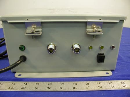
Click to zoom
Application Details
- Equipment Class
- AMP - Amplifier
- Date of Grant
- Aug 10, 2003
- Application Purpose
- Original Equipment
- Date of Application
- Aug 10, 2003
- Equipment Note
- Bi-Directional Amplifier
- Frequency Range
- 935.00000000 - 940.00000000
- Company
- Communication Components Inc
- Country
- United States
Documents & Files
Document Text
Text extracted from the exhibit documents filed with the FCC. Open a document above to read the original.
Users Manual
BDA TEST AND INSTALLATION PROCEDURE 1. INSPECTION Open the enclosure of the bi-directional amplifier (BDA) and carefully inspect the inside assembly of the unit. Verify that all components are properly secured to the base of the enclosure, there are no loose parts, and all interconnections are reliable. Carefully close the enclosure. Unpack the outdoor and indoor antennas and inspect the content. Verify that there are no loose parts or rattling in the antennas. Make sure that antennas are not deformed. 2. SITE INSTALLATION 2.1 "Donor" (outdoor) Antenna Installation On the roof of the building choose the location of the "donor" Yagi antenna. Point the antenna towards the "donor" site. Connect the mobile phone or spectrum analyzer to the antenna using a short cable with type "N" connector on the antenna side and a proper adapter on the test equipment side. Adjust the position of the antenna for maximum reading. The average power level should not be below -90 dBm. Record the measured data. Install the antenna following instructions from the antenna manufacturer. CAUTION: Maximum Antenna gain shall be 15dBi. A minimum separation distance of 65 centimeters between the transmit antenna and nearby persons must be maintained. If this separation distance is not maintained, the device may not be in compliance with FCC RF Exposure rules. 2.2 Surge Protector Installation Connect the cable run to the antenna and pass it through the roof manifold. Inside of the building find a location for the surge protector near the construction ground where it can be reliably grounded. Install the surge protector and connect the cables to both sides. Bring the cable run to the BDA location. Using a spectrum analyzer or mobile phone, measure the signal from the "donor" site. It is typically from 1 dB to 3 dB below the antenna output level. Exact loss depends on the cable type and length of the cable. CAUTION Use caution working with the bi-directional amplifier. Disconnect the 115 VAC from the amplifier prior to inspection. 2.3 Indoor Antenna (s) Installation . From preliminary evaluation of the blueprints of the service area, the approximate locations of the indoor antennas must be established. The level of the signal at the boundary of the service area can be a guideline for the location of the antennas. Several parameters must be considered: a) The gain of the Omni antenna is 0 dBd. b) The free space propagation loss is approximately -60 dB per 100 ft. c) The acceptable level at the lowest signal position for the mobile is -80 dBm. Following the installation instructions mount antennas on the ceiling tiles or any other appropriate location. Run the cables from antennas to the BDA location. Use a power combiner, if needed, to interconnect the antenna cables. CAUTION: Maximum Antenna gain shall be 15dBi. A minimum separation distance of 65 centimeters between the transmit antenna and nearby persons must be maintained. If this separation distance is not maintained, the device may not be in compliance with FCC RF Exposure rules. 2.4 BDA Installation The bi-directional amplifier can be installed as a freestanding unit lying on the shelf of a cabinet or any other adequately strong support. It can also be secured by screws to the wall or rack using four holes in the tabs located at the back plate of the enclosure. AC power must be available in the vicinity of the BDA. It is recommended that the environmental temperature will not exceed 50 C and the area will be adequately ventilated. Once amplifier is installed in place, open the front door and verify that all internal parts are securely mounted. Connect the ground wire to the ground stud on the enclosure. Plug in the AC cable into the AC socket. The green light on the enclosure must be lit on. a) Downlink Gain Setting. Connect the cable from the lightning protector and “DONOR” antenna to the “DONOR” port of the BDA. Connect a power meter or spectrum analyzer to the "SERVICE" port (Uplink input connector) of the BDA. Measure the power of the signal at the “SERVICE” port of the BDA. The Power level should not exceed the maximum FCC power rating of the BDA for the type of signal being amplified. These power levels will guarantee the intermodulation products below -13 dBm, which is in compliance with FCC regulation. After the output power level is set correctly, connect the donor antenna cable to the "DONOR" port of the BDA. b) Uplink Gain Setting. Connect the indoor (service area) antenna cable to the "SERVICE" port of the BDA. Initiate the call from the closest position of the mobile to the service area antenna. Observe the yellow "Uplink AGC ON" light on BDA enclosure. The threshold of the AGC in the uplink amplifier is factory preset at the gain that corresponds to the intermodulation products level of -13 dBm. If the signal level is low and AGC light is not "ON", slowly increase the gain of the downlink amplifier until the light will be lit. Back off the potentiometer just below the level when the light is off. Check the security of the installation and presence of the AC power. Amplifier is ready for operation. 3. REMOVE BI-DIRECTIONAL AMPLIFIER 3.1 Unplug the AC cord from the socket. AC light on the amplifier must be off. Disconnect all coaxial cables. 3.2 Dismount amplifier from the wall or remove it from the shelf. 4. SHIPMENT AND STORAGE OF THE BDA 4.1 Use common technical shop practices to ensure equipment protection during shipment or storage. 5. TROUBLESHOOTING AND FAULT DETECTION 5.1 Check the presence of the AC power. The AC light must be on. 5.2 Check the continuity of all connecting cables. 5.3 If the fault was not located, remove the amplifier and send it to the manufacturer for repair. 5.4 RF testing of the amplifier is possible in the specially equipped laboratory. 6. INFORMATION TO USER This equipment complies with part 15 of the FCC rules. Any changes or modifications to this product as well as usage outside of specified electrical parameters, which a…
Text truncated - open the document above for the full version.
Cover Letter(s)
REQUEST FOR CONFIDENTIALITY Communication Components Inc. would like to request confidentiality with regard to the following documents in the filing for equipment approval identified by FCC ID. No. NT3BDA-8087-80. (1) Schematic diagrams and Parts List contained in electronic file identified as BDA Parts List & Schematic.pdf. It is the opinion of Communication Components Inc. disclosure of this information would result in significant loss of revenue. This information should be kept confidential for 10 years. Authorized signature: Printed name: Dennis Nathan Company name: Communication Components Inc. Company Address: 89 Leuning Street, South Hackensack, NJ 07606 COMMUNICATION COMPONENTS INC Extending Wireless Coverage 89 Leuning Street Phone: 201-342-3338 2 nd Floor Fax: 201-342-3339 South Hackensack, NJ 07606 www.cciproducts.com
External Photos
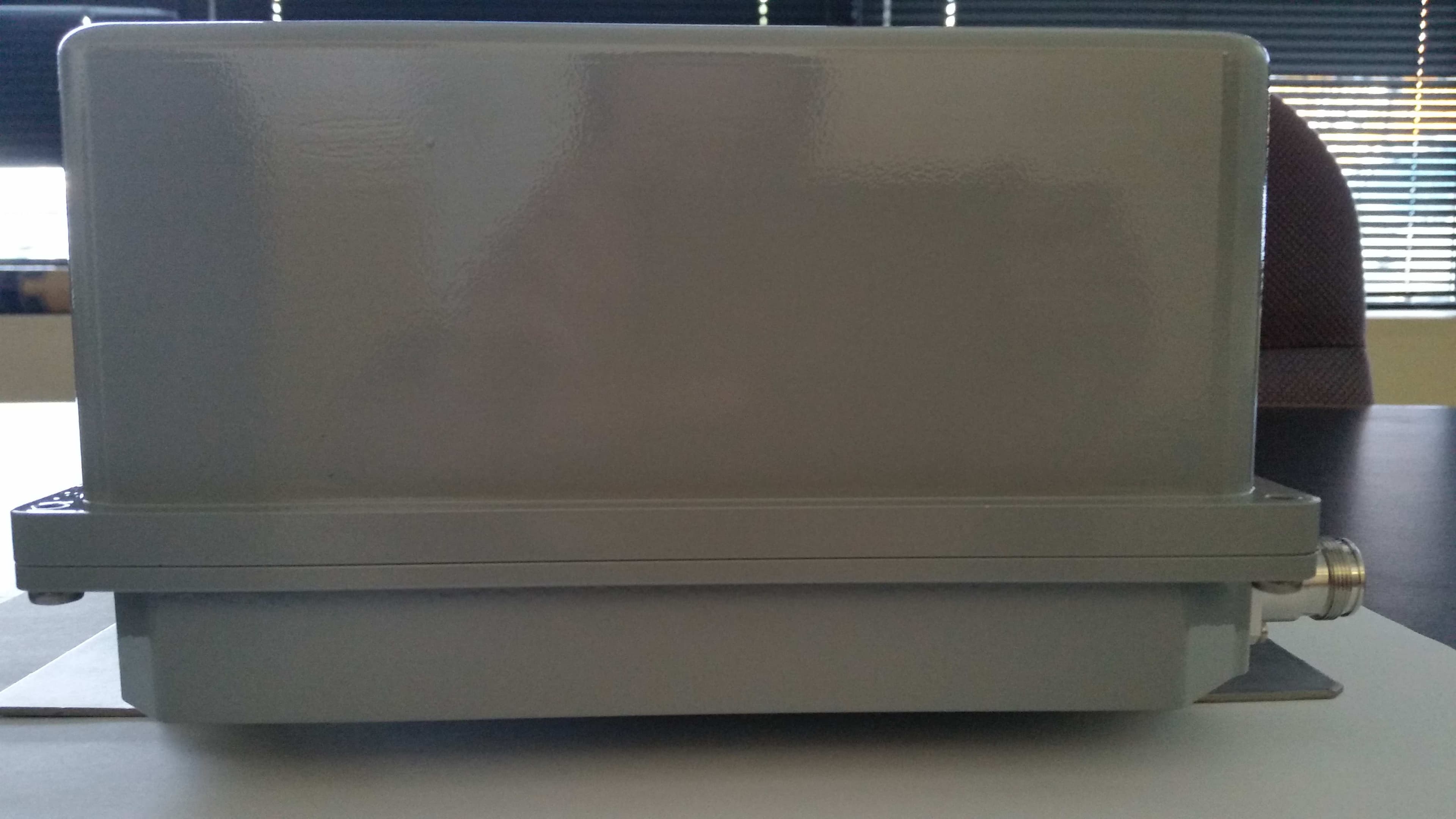
Communication Components Inc. FCC ID: NT3BDA-8087-80 EXHIBIT C - EUT PHOTOGRAPHS EUT – Top View EUT – Bottom View Communication Components Inc. FCC ID: NT3BDA-8087-80 EUT - Port View EUT – Whole View
ID Label/Location Info
EXHIBIT A - FCC PRODUCT LABELING AND WARNING STATEMENT FCC ID Label Specifications: Text is black or white in color and is left justified. Labels are silk-screened and shall be “permanently affixed” at a conspicuous location on the EUT. Proposed Label Location on EUT Bottom View of the EUT / Proposed Label Location FCC Warning Statement A FCC Warning Statement is provided in the product manual. FCC ID: Q4EUSHR-800 FCC ID: NT3BDA-8087-80
Internal Photos
Communication Components Inc. FCC ID: NT3BDA-8087-80 EUT – Cover off View EUT – Amplifier Unit Communication Components Inc. FCC ID: NT3BDA-8087-80 EUT – Amplifier Module EUT – Amplifier Front Communication Components Inc. FCC ID: NT3BDA-8087-80 EUT – Amplifier Back EUT – Alarm Front Communication Components Inc. FCC ID: NT3BDA-8087-80 EUT – Alarm Back
Operational Description
Tel: 201-342-3338 Fax: 201-342-3339 Email: [email protected] Technical Description General Information Communication Components, Inc. Bi- directional Amplifier (BDA) improves the sensi- tivity of base stations in indoor locations where there is a significant amount of propagation loss in RF distribution systems. The BDA block is available for operation in all Cellular SMR800 & SMR900 operating frequency bands with different maximum gain values. The BDA is ideal for use any structures with limited signal penetration such as office build- ings, industrial facilities, tunnels and subways and is suitable for installation in the most de- manding indoor and outdoor environments. General Info and Technical Description 1 Electrical Specifications Block Diagram 2 Mechanical Drawings 3 Contents The BDA was specifically designed for low system group delay to mini- mize the Bit-Error-Rate (BER) of digital transmissions. The BDA block consists of a single compact unit with two RF connectors. It is rugged and can be easily connected during cable installation. It has a moisture proof NEMA 4X enclosure suitable for indoor and outdoor instal- lation with two low noise medium power amplifiers, independently con- trolled up-link and down-link Attenuators and Automatic Gain Control (AGC), dual duplexers, and bias tee’s. The BDA can be powered by a conventional 110/220 VAC source using a built in power supply or, alternatively, DC voltage can be supplied to the BDA via an external DC input or via the center conductor of the RF coax cable. Automatic Gain Control (AGC) and Manual Gain Control (MGC) is avail- able in both the up-link & down-link path with over 30 dB attenuation range to eliminate the possibility of saturating the amplifier and maintain- ing the inter-modulation products at an acceptable level during all operat- ing conditions. An optional microprocessor based monitoring and alarm interface is available to check all BDA system parameters and report status to a local or remote controller. Communication Components Inc. Options • 01: 110/220 VAC Input • 02: External DC Input • 03: Coax DC Input (Internal bias tee) • 04: Up and Down Link At- tenuators • 05: Automatic Bypass Switch- ing • 06: Monitoring Interface • 07: Automatic Gain Control (AGC) Bi-directional Amplifier for Cellular & SMR Bands Model BDA-8087-80-SMR800 Model BDA-8087-80-SMR900 Model BDA-8087-80-CELLA Model BDA-8087-80-CELLB Model BDA-8087-80-CELLA&B Model: BDA-8087-80-SMR800 806 - 821 MHz 851 - 866 MHz Model: BDA-8087-80-SMR900 896 - 901 MHz 935 - 940 MHz System Gain @ 0 dB attenuation: 80 dB min., 82 dB Typical System Noise Figure: 3 dB Max., 2.5 dB Typical System Group Delay: 180 nanosecond Max. Pass-band Ripple: 0.5 dB P-P Max. Output Third Order Intercept Point: +46 dBm Min., +47 dBm Typical 1 dB Compression Point: +30 dBm Min., +31 dBm Typical Input /Output VSWR: 1.5:1 Max. Up-Link-Down-Link Isolation 90 dB Manual Gain Control (MGC) Attenuation Type: Variable Attenuation Range: 31 dB Min. in 1dB Steps Automatic Gain Control (AGC) Attenuation Range: 20 dB Min., 30 dB Typical Operating Voltage: 115/220 VAC or 12VDC Dimensions: 12”x 10”x 5” Enclosure: NEMA 4X Weather Proof Connectors: N Type female Weight: 10 Lbs. Max. Mounting: Mounting Ears for any surface installations SPECIFICATION Up-Link Frequency Range Down-Link Frequency Range Model BDA-8087-80-CELL A 824-835 & 845-846.5 MHz 869-880 & 890-891.5 MHz Model BDA-8087-80-CELL B 835-845 & 846.5-849 MHz 880-890 & 891.5-894 MHz Model BDA-8087-80-CELL A&B 824 - 849 MHz 869 - 894 MHz Maximum Input Level: -50dBm @ 0dB Attenuation, -19dBm @ 31dB Attenuation Setting Bi-directional Amplifier Electrical & Mechanical Specification Communication Components Inc. Bi-directional Amplifier for Cellular & SMR Bands Communication Components Inc. Tel: 201-342-3338 Fax: 201-342-3339 * The output power set point for the AGC circuit can be factory preset to the customers requirement to limit 3rd order IM for multiple carriers. Unless otherwise specified, the AGC set point will be set to limit the 3rd order IM products to below -13 dBm. 89 Leuning Street South Hackensack, NJ 07606 Tel: 201-342-3338 Fax: 201-342-3339 Email: [email protected] Communication Components Inc. W w w . c c i p r o d u c t s . c o m BDA Indoor/Outdoor Unit Mechanical Diagram Communication Components Inc. BI-DIRECTIONAL AMPLIFIER 10” 12” UP-LINK 5 ” Block Diagram Rx/Tx DUPLEXER Rx BPF Tx BPF Rx/Tx DUPLEXER BIAS TEE Rx BPF Tx BPF BIAS TEE AMP AMP AGC AMP AMP AGC POWER SUPPLY Monitor/ Alarm Ordering Information • Model BDA-8087-80-SMR800: For SMR 800 Band Operation • Model BDA-8087-80-SMR900: For SMR 900 Band Operation • Model BDA-8087-80-CELLA: For Cellular A Band Operation • Model BDA-8087-80-CELLB: For Cellular B Band Operation • Model BDA-8087-80-CELLA&B For Cellular A&B Band Operation
Parts List/Tune Up Info
BDA TEST AND INSTALLATION PROCEDURE 1. INSPECTION Open the enclosure of the bi-directional amplifier (BDA) and carefully inspect the inside assembly of the unit. Verify that all components are properly secured to the base of the enclosure, there are no loose parts, and all interconnections are reliable. Carefully close the enclosure. Unpack the outdoor and indoor antennas and inspect the content. Verify that there are no loose parts or rattling in the antennas. Make sure that antennas are not deformed. 2. SITE INSTALLATION 2.1 "Donor" (outdoor) Antenna Installation On the roof of the building choose the location of the "donor" Yagi antenna. Point the antenna towards the "donor" site. Connect the mobile phone or spectrum analyzer to the antenna using a short cable with type "N" connector on the antenna side and a proper adapter on the test equipment side. Adjust the position of the antenna for maximum reading. The average power level should not be below -90 dBm. Record the measured data. Install the antenna following instructions from the antenna manufacturer. CAUTION: Maximum Antenna gain shall be 15dBi. A minimum separation distance of 65 centimeters between the transmit antenna and nearby persons must be maintained. If this separation distance is not maintained, the device may not be in compliance with FCC RF Exposure rules. 2.2 Surge Protector Installation Connect the cable run to the antenna and pass it through the roof manifold. Inside of the building find a location for the surge protector near the construction ground where it can be reliably grounded. Install the surge protector and connect the cables to both sides. Bring the cable run to the BDA location. Using a spectrum analyzer or mobile phone, measure the signal from the "donor" site. It is typically from 1 dB to 3 dB below the antenna output level. Exact loss depends on the cable type and length of the cable. CAUTION Use caution working with the bi-directional amplifier. Disconnect the 115 VAC from the amplifier prior to inspection. 2.3 Indoor Antenna (s) Installation . From preliminary evaluation of the blueprints of the service area, the approximate locations of the indoor antennas must be established. The level of the signal at the boundary of the service area can be a guideline for the location of the antennas. Several parameters must be considered: a) The gain of the Omni antenna is 0 dBd. b) The free space propagation loss is approximately -60 dB per 100 ft. c) The acceptable level at the lowest signal position for the mobile is -80 dBm. Following the installation instructions mount antennas on the ceiling tiles or any other appropriate location. Run the cables from antennas to the BDA location. Use a power combiner, if needed, to interconnect the antenna cables. CAUTION: Maximum Antenna gain shall be 15dBi. A minimum separation distance of 65 centimeters between the transmit antenna and nearby persons must be maintained. If this separation distance is not maintained, the device may not be in compliance with FCC RF Exposure rules. 2.4 BDA Installation The bi-directional amplifier can be installed as a freestanding unit lying on the shelf of a cabinet or any other adequately strong support. It can also be secured by screws to the wall or rack using four holes in the tabs located at the back plate of the enclosure. AC power must be available in the vicinity of the BDA. It is recommended that the environmental temperature will not exceed 50 C and the area will be adequately ventilated. Once amplifier is installed in place, open the front door and verify that all internal parts are securely mounted. Connect the ground wire to the ground stud on the enclosure. Plug in the AC cable into the AC socket. The green light on the enclosure must be lit on. a) Downlink Gain Setting. Connect the cable from the lightning protector and “DONOR” antenna to the “DONOR” port of the BDA. Connect a power meter or spectrum analyzer to the "SERVICE" port (Uplink input connector) of the BDA. Measure the power of the signal at the “SERVICE” port of the BDA. The Power level should not exceed the maximum FCC power rating of the BDA for the type of signal being amplified. These power levels will guarantee the intermodulation products below -13 dBm, which is in compliance with FCC regulation. After the output power level is set correctly, connect the donor antenna cable to the "DONOR" port of the BDA. b) Uplink Gain Setting. Connect the indoor (service area) antenna cable to the "SERVICE" port of the BDA. Initiate the call from the closest position of the mobile to the service area antenna. Observe the yellow "Uplink AGC ON" light on BDA enclosure. The threshold of the AGC in the uplink amplifier is factory preset at the gain that corresponds to the intermodulation products level of -13 dBm. If the signal level is low and AGC light is not "ON", slowly increase the gain of the downlink amplifier until the light will be lit. Back off the potentiometer just below the level when the light is off. Check the security of the installation and presence of the AC power. Amplifier is ready for operation. 3. REMOVE BI-DIRECTIONAL AMPLIFIER 3.1 Unplug the AC cord from the socket. AC light on the amplifier must be off. Disconnect all coaxial cables. 3.2 Dismount amplifier from the wall or remove it from the shelf. 4. SHIPMENT AND STORAGE OF THE BDA 4.1 Use common technical shop practices to ensure equipment protection during shipment or storage. 5. TROUBLESHOOTING AND FAULT DETECTION 5.1 Check the presence of the AC power. The AC light must be on. 5.2 Check the continuity of all connecting cables. 5.3 If the fault was not located, remove the amplifier and send it to the manufacturer for repair. 5.4 RF testing of the amplifier is possible in the specially equipped laboratory. 6. INFORMATION TO USER This equipment complies with part 15 of the FCC rules. Any changes or modifications to this product as well as usage outside of specified electrical parameters, which a…
Text truncated - open the document above for the full version.
RF Exposure Info
RF EXPOSURE According to §15.247(b)(4) and §1.1307(b)(1), systems operating under the provisions of this section shall be operated in a manner that ensures that the public is not exposed to radio frequency energy level in excess of the Commission’s guidelines. According to §1.1310 and §2.1093 RF exposure is calculated. Limits for Maximum Permissive Exposure (MPE) Frequency Range (MHz) Electric Field Strength (V/m) Magnetic Field Strength (A/m) Power Density (mW/cm 2 ) Averaging Time (minute) Limits for General Population/Uncontrolled Exposure 0.3-1.346141.63*(100)30 1.34-30824/f2.19/f*(180/f 2 )30 30-30027.50.0730.230 300-1500//f/150030 1500-15000//1.030 f = frequency in MHz * = Plane-wave equivalent power density MPE Prediction Predication of MPE limit at a given distance Equation from page 18 of OET Bulletin 65, Edition 97-01 S = PG/4πR² Where: S = power density P = power input to antenna G = power gain of the antenna in the direction of interest relative to an isotropic radiator R = distance to the center of radiation of the antenna Maximum peak output power at antenna input terminal: 29.7 (dBm) Maximum peak output power at antenna input terminal: 933 (mW) Prediction distance: 65 (cm) Predication frequency: 850 (MHz) Antenna Gain (typical): 15 (dBi) antenna gain: 31.6 (numeric) Power density at predication frequency at 65 cm: 0.55 (mW/cm 2 ) MPE limit for uncontrolled exposure at prediction frequency: 0.57 (mW/cm 2 ) Test Result The EUT is a mobile device. The predicted power density level at 65 cm is 0.55 mW/cm². It is below the uncontrolled exposure limit of 0.57mW/cm² at 850 MHz.
Test Report
Note: This test report is specially limited to the above client company and the product model only. It may not be duplicated without prior written consent of Bay Area Compliance Laboratory Corporation. This report must not be used by the client to claim product endorsement by NVLAP or any agency of the U.S. Government. FCC PART 22 & 90 TYPE APPROVAL EMI MEASUREMENT AND TEST REPORT For Communication Components Inc. 89 Leuning Street 2 nd Floor South Hackensack, NJ 07606 FCC ID: NT3BDA-8087-80 2003-05-15 This Report Concerns: Original Report Equipment Type: Bi-Directional Amplifier Test Engineer:Benjamin Jing Report No.:R0210307 Test Date:2003-03-01 Reviewed By:Hans Mellberg Prepared By:Bay Area Compliance Laboratory Corporation 230 Commercial Street Sunnyvale, CA 94085 Tel: (408) 732-9162 Fax: (408) 732 9164 Communication Components Inc. FCC ID: NT3BDA-8087-80 Report # R0210307RptPage 2 of 125FCC PART 22 & 90 Type Approval report TABLE OF CONTENTS 1 - GENERAL INFORMATION.................................................................................................................................................4 1.1 PRODUCT DESCRIPTION FOR EQUIPMENT UNDER TEST (EUT).........................................................................................4 1.2 OBJECTIVE................................................................................................................................................................................4 1.3 RELATED SUBMITTAL(S)/GRANT(S)......................................................................................................................................4 1.4 TEST METHODOLOGY.............................................................................................................................................................4 1.5 TEST FACILITY.........................................................................................................................................................................4 1.6 TEST EQUIPMENT LIST AND DETAILS...................................................................................................................................5 1.7 LOCAL SUPPORT EQUIPMENT LIST AND DETAILS...............................................................................................................5 1.8 EXTERNAL I/O CABLING LIST AND DETAILS......................................................................................................................6 2 - SYSTEM TEST CONFIGURATION..................................................................................................................................7 2.1 JUSTIFICATION.........................................................................................................................................................................7 2.2 SCHEMATICS/BLOCK DIAGRAM............................................................................................................................................7 2.3 TEST SETUP BLOCK DIAGRAM..............................................................................................................................................7 2.4 EQUIPMENT MODIFICATIONS.................................................................................................................................................7 3 - SUMMARY OF TEST RESULTS........................................................................................................................................8 4 – CONDUTED OUTPUT POWER........................................................................................................................................9 4.1 APPLICABLE STANDARD.........................................................................................................................................................9 4.2 TEST PROCEDURE....................................................................................................................................................................9 4.3 TEST EQUIPMENT.....................................................................................................................................................................9 4.4 TEST RESULTS........................................................................................................................................................................10 5 - EMISSION BANDWIDTH...................................................................................................................................................12 5.1 APPLICABLE STANDARDS.....................................................................................................................................................12 5.2 TEST PROCEDURE..................................................................................................................................................................12 5.3 TEST EQUIPMENT..................................................................................................................................................................12 5.4 PLOTS OF OCCUPIED BANDWIDTH......................................................................................................................................12 6 – SPURIOUS EMISSIONS AT ANTENNA TERMINALS...........................................................................................76 6.1 APPLICABLE STANDARDS.....................................................................................................................................................76 6.2 TEST PROCEDURE..................................................................................................................................................................76 6.3 TEST EQUIPMENT..................................................................................................................................................................76 6.4 TEST RESULTS.......…
Text truncated - open the document above for the full version.
Test Report
Communication Components Inc. FCC ID: NT3BDA-8087-80 Report # R0210307RptPage 41 of 125FCC PART 22 & 90 Type Approval report Communication Components Inc. FCC ID: NT3BDA-8087-80 Report # R0210307RptPage 42 of 125FCC PART 22 & 90 Type Approval report Communication Components Inc. FCC ID: NT3BDA-8087-80 Report # R0210307RptPage 43 of 125FCC PART 22 & 90 Type Approval report Communication Components Inc. FCC ID: NT3BDA-8087-80 Report # R0210307RptPage 44 of 125FCC PART 22 & 90 Type Approval report Communication Components Inc. FCC ID: NT3BDA-8087-80 Report # R0210307RptPage 45 of 125FCC PART 22 & 90 Type Approval report Communication Components Inc. FCC ID: NT3BDA-8087-80 Report # R0210307RptPage 46 of 125FCC PART 22 & 90 Type Approval report Communication Components Inc. FCC ID: NT3BDA-8087-80 Report # R0210307RptPage 47 of 125FCC PART 22 & 90 Type Approval report Communication Components Inc. FCC ID: NT3BDA-8087-80 Report # R0210307RptPage 48 of 125FCC PART 22 & 90 Type Approval report Communication Components Inc. FCC ID: NT3BDA-8087-80 Report # R0210307RptPage 49 of 125FCC PART 22 & 90 Type Approval report Communication Components Inc. FCC ID: NT3BDA-8087-80 Report # R0210307RptPage 50 of 125FCC PART 22 & 90 Type Approval report Communication Components Inc. FCC ID: NT3BDA-8087-80 Report # R0210307RptPage 51 of 125FCC PART 22 & 90 Type Approval report Communication Components Inc. FCC ID: NT3BDA-8087-80 Report # R0210307RptPage 52 of 125FCC PART 22 & 90 Type Approval report Communication Components Inc. FCC ID: NT3BDA-8087-80 Report # R0210307RptPage 53 of 125FCC PART 22 & 90 Type Approval report Communication Components Inc. FCC ID: NT3BDA-8087-80 Report # R0210307RptPage 54 of 125FCC PART 22 & 90 Type Approval report Communication Components Inc. FCC ID: NT3BDA-8087-80 Report # R0210307RptPage 55 of 125FCC PART 22 & 90 Type Approval report Communication Components Inc. FCC ID: NT3BDA-8087-80 Report # R0210307RptPage 56 of 125FCC PART 22 & 90 Type Approval report Communication Components Inc. FCC ID: NT3BDA-8087-80 Report # R0210307RptPage 57 of 125FCC PART 22 & 90 Type Approval report Communication Components Inc. FCC ID: NT3BDA-8087-80 Report # R0210307RptPage 58 of 125FCC PART 22 & 90 Type Approval report Communication Components Inc. FCC ID: NT3BDA-8087-80 Report # R0210307RptPage 59 of 125FCC PART 22 & 90 Type Approval report Communication Components Inc. FCC ID: NT3BDA-8087-80 Report # R0210307RptPage 60 of 125FCC PART 22 & 90 Type Approval report Communication Components Inc. FCC ID: NT3BDA-8087-80 Report # R0210307RptPage 61 of 125FCC PART 22 & 90 Type Approval report Communication Components Inc. FCC ID: NT3BDA-8087-80 Report # R0210307RptPage 62 of 125FCC PART 22 & 90 Type Approval report Communication Components Inc. FCC ID: NT3BDA-8087-80 Report # R0210307RptPage 63 of 125FCC PART 22 & 90 Type Approval report Communication Components Inc. FCC ID: NT3BDA-8087-80 Report # R0210307RptPage 64 of 125FCC PART 22 & 90 Type Approval report Communication Components Inc. FCC ID: NT3BDA-8087-80 Report # R0210307RptPage 65 of 125FCC PART 22 & 90 Type Approval report
Test Report
Communication Components Inc. FCC ID: NT3BDA-8087-80 Report # R0210307RptPage 66 of 125FCC PART 22 & 90 Type Approval report Communication Components Inc. FCC ID: NT3BDA-8087-80 Report # R0210307RptPage 67 of 125FCC PART 22 & 90 Type Approval report Communication Components Inc. FCC ID: NT3BDA-8087-80 Report # R0210307RptPage 68 of 125FCC PART 22 & 90 Type Approval report Communication Components Inc. FCC ID: NT3BDA-8087-80 Report # R0210307RptPage 69 of 125FCC PART 22 & 90 Type Approval report Communication Components Inc. FCC ID: NT3BDA-8087-80 Report # R0210307RptPage 70 of …
Text truncated - open the document above for the full version.
Contact Information
Applicant
Dennis Nathan(President)
Test Firm
Bay Area Compliance LaboratoryJohn Chan
Technical Specifications
| # | Rule Parts | Frequency Range | Power Output | Emission |
|---|---|---|---|---|
| 44 | 9 | 935 MHz - 940 MHz | 912.00 mW | F3E |
Other Applications from Communication Components Inc
NT3SERRFU8W
Mar 09, 2020SiriusXM SDAR Fiber Repeater
Equipment Class
BOS - All other signal boosters other than 20.21/90.219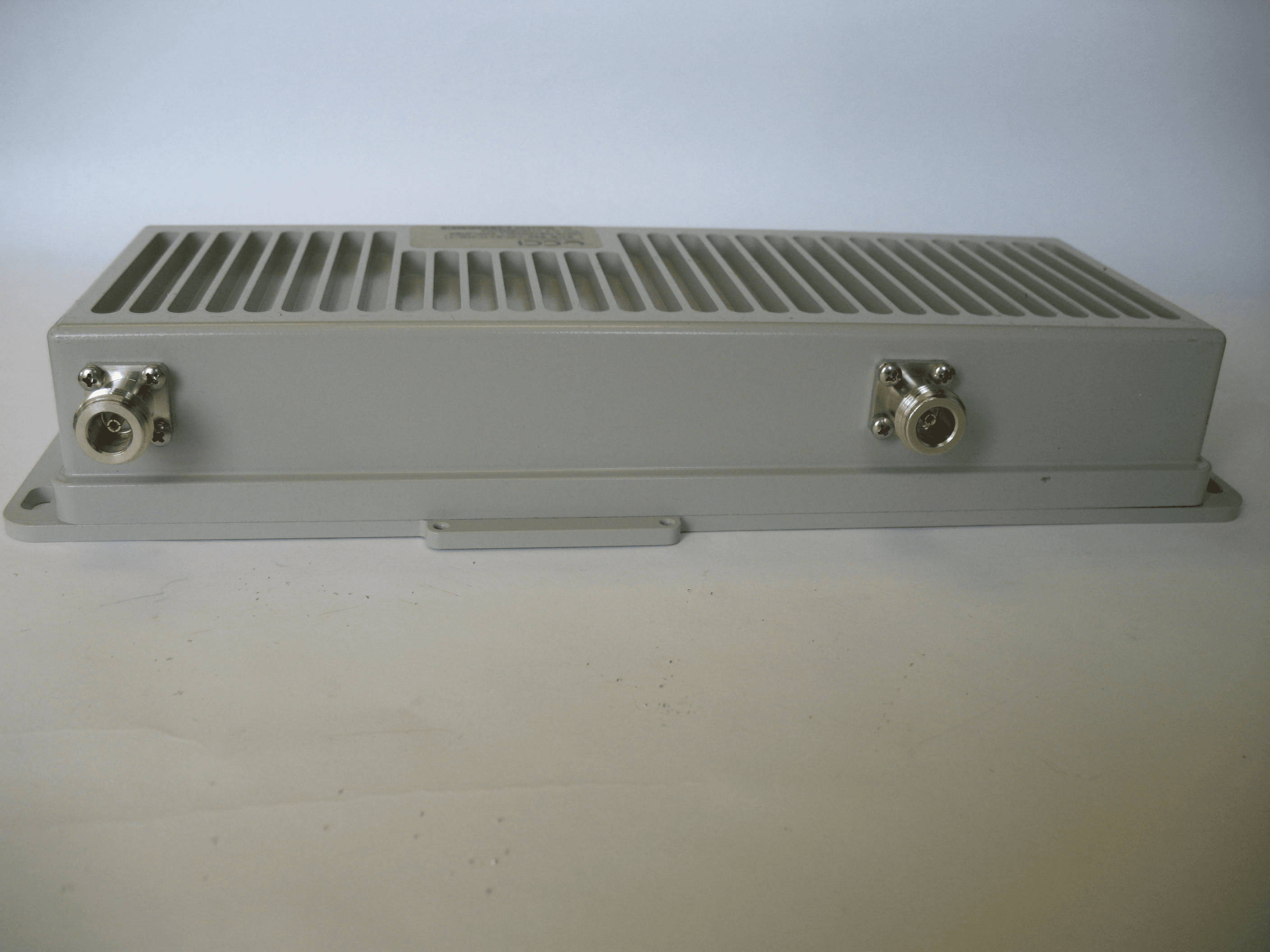
NT3SCB8501WA
Jun 24, 2014Amplifier
Equipment Class
AMP - Amplifier
NT3MCPA2100125
Apr 19, 2011HIGH EFFICIENCY MCPA
Equipment Class
AMP - Amplifier
NT3DAB1819125G2
Jul 28, 2010PCS GSM/EDGE 125W Dual Amplifier Booster
Equipment Class
AMP - Amplifier
NT3CE-1819-10G2
Jul 03, 2007PCS Multi-Channel Cell Extender
Equipment Class
AMP - Amplifier