NT3CE-1819Amplifier
Communication Components Inc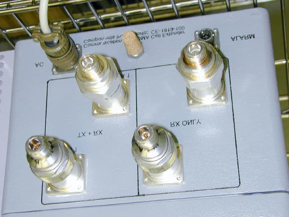
Click to zoom
Application Details
- Equipment Class
- AMP - Amplifier
- Date of Grant
- Jul 28, 2001
- Application Purpose
- Original Equipment
- Date of Application
- Jul 28, 2001
- Equipment Note
- Amplifier
- Frequency Range
- 1930.00000000 - 1990.00000000
- Company
- Communication Components Inc
- Country
- United States
Documents & Files
Document Text
Text extracted from the exhibit documents filed with the FCC. Open a document above to read the original.
Users Manual
Communication Components Inc.Communication Components Inc. Communication Components Inc.Communication Components Inc. Communication Components Inc. 89 Leuning Street, S.Hackensack, NJ 07606 TEL: 201-342-3338FAX: 201-342-3339 Cell Extender for Cell Extender for CDMA/TDMACDMA/TDMA Base Stations Base Stations General Information: Communication Component Inc.’s Cell Extender products are designed to extend the range and coverage area of CDMA/TDMA type base stations in PCS wireless communications. Up-Link loading equation shows that the number of subscribers is directly proportional to Eb/Io ratio and also depends on the receiver noise to interference ratio. The Cell Extender boosts the output power of the base station and, by increasing its ERP, increases the first parameter. It also minimizes receiver noise level to decrease the second parameter.As a result of these improvements, the number of subscribers in each sector where thecell extender is used, is increased allowing for cost efficient implementation of high capacity radio networks. It also provides low-noise amplification of the receive signal to improve system sensitivity and to maintain a balanced link between the transmit and receive signals. The Cell Extender is especially helpful on sites at the fringe of the covered territory, highway sites, or any site with tall tower, and can be cost efficient and much more reliable alternative to the repeater or TMA implementation. The Cell Extender is easy to install, requires no maintenance, and is fully compatible with any CDMA Base Station equipment. The Cell Extender offers maximum installation flexibility by allowing to be installed at the bottom of the tower or on the top of the tower. Cell Extender provides additional failure protection by including the by-pass circuitry which is activated in case of the HPA or LNA failure. In this case the base station can continue to operate with slightly degraded parameters. •Configuration 1-The Cell Extender is mounted on the tower structure, in close proximity to the antenna. This configuration is ideal for environments whereAC lines are not easily available on the mounting structure. For this configuration, the Cell Extender should be ordered with the Remote Power Option which includes a Bias-t and Remote Power Supply module to provide DC power to the Cell Extender over the coaxial cable. •Configuration 2-The Cell Extender is installed at the BTS level. This is intended for applications where it is impractical to install any equipment other than the antenna on the mounting structure. Communication Components Inc.Communication Components Inc. Communication Components Inc.Communication Components Inc. Description: The Cell Extender is specifically designed for compatibility with any CDMA Base Station Equipment and is ensured to maintain the integrity of the signalupon amplification. This is achieved by utilizing state-of-the-art LDMOS technology for power amplification, monolithic Gallium-Arsenide technology for low noise receive amplification, and with particular emphasis on low system group delay and linearity to minimize Bit-Error-Rate (BER) of digital transmissions. The Cell Extender design is based on the building block approachand can be easily configured for different type of base stations. It can contain equipment for two channels or for single channel. Two channel operation allows to preserve diversity feature in a single box.. For different base stations the half-duplex or full duplex approach can be utilized. CE-1819 consists of a single compact unit with RF connectors and a single AC linefor power or without it, if bias-T option is included.. It is housed in a moisture proof NEMA 4X aluminum die-cast enclosure with integrated heat sinks and is suitable for either outdoor or indoor installations. The Cell Extender is designed to improve the performance of the whole transceiver unit that is provided with EBTS. It contains redundant low noise amplifiers to boost the receive signals, redundant LDMOS-based high power amplifiers to boost the transmit signal, duplexers, an integrated power supply and alarm/control circuitry to monitor the operation of the unit andthe by-pass circuitry. The Cell Extender is powered by a conventional 110/220 VAC source or be optionally DC-powered via the coax cable using the Remote Power Option. Ordering Information:Options: Model CE-1819 01: Single Channel Only 02: Monitoring Interface 03: Remote Power Option (with internal Bias-T) -D: A & D Band Operation -B: B Band Operation -C: C Band Operation Communication Components Inc.Communication Components Inc. Communication Components Inc.Communication Components Inc. Electrical Specification :Up-LinkDown-Link • Model CE-1819-ADA&D Block:1850-1870 MHz 1930-1950MHz •Model CE-1819-B B Block:1870-1885 MHz 1950-1965MHz •Model CE-1819-C C Block:1895-1910 MHz 1975-1990MHz •Downlink: System Gain 3 to 8 dB Gain Flatness± 0.5 dB Max Operating Output Power/Single Carrier (meeting ACPL CDMA requirements) 20 Watts Max Output Third Order Intercept Point:+50 dBm Typ Input/Output VSWR1.5:1 Max •Uplink: System Gain 4 to 12 dB Gain Flatness± 0.5 dB Max Noise Figure:2.5 dB Max. Output Third Order Intercept Point:+30 dBm Min. Input/Output VSWR1.5:1 Max •Up-link/Down-link Isolation80 dB Min •By-Pass Insertion Loss 0.5 dB •Operating Voltage:115/220VAC or 28VDC •Current Consumption:3 A @ 120VAC Alarms Onecommon alarm is standard Mechanical Specifications : • Dimensions:14”x 8”x 7” •Enclosure:NEMA 4X Aluminum Die-cast •Connectors:“ N” or 7/16 DIN •Weight:20 Lbs. Max. •Mounting:Mounting Studs Communication Components Inc.Communication Components Inc. Communication Components Inc.Communication Components Inc. CDMA Cell Extender BLOCK DIAGRAM Monitor/ Alarm (optional) Power Supply Rx+Tx to Antenna A1 Communication Components Inc.Communication Components Inc. Communication Components Inc.Communication Components Inc. 89 Leuning StreetTel: 201 342-3338 S.Hackensack, NJ 07606Fax: 201 342-3339…
Text truncated - open the document above for the full version.
Block Diagram
CDMA Cell Extender BLOCK DIAGRAM Monitor/ Alarm (optional) Power Supply Rx+Tx to Antenna A1 Communication Components Inc.Communication Components Inc. Communication Components Inc.Communication Components Inc. 89 Leuning StreetTel: 201 342-3338 S.Hackensack, NJ 07606Fax: 201 342-3339 Communication Components Inc.Communication Components Inc. Communication Components Inc.Communication Components Inc. 89 Leuning StreetTel: 201 342-3338 S.Hackensack, NJ 07606Fax: 201 342-3339 LNA PA Rx/Tx DUPLEXER Rx BPF Tx BPF Rx/Tx DUPLEXER Rx BPF Tx BPF Rx/Tx from EBTS BIAS-T (optional) BIAS-T (optional) Rx/Tx DUPLEXER Rx BPF Tx BPF LNA Rx to Antenna A12 Rx to EBTS THIS EQUIPMENT COMPLIES WITH PART 15 OF THE FCC RULES. ANY CHANGES OR MODIFICATIONS NOR EXPRESSLY APPROVED BY MANUFACTURER COULD VOID USER’S AUTHORITY TO OPERATE THE EQUIPMENT
Cover Letter(s)
Good morning Barry 1) Photos attached. Hope these are better. <<photos.zip>> 2) There is no tune-up procedure done by the client. It has to be done by the manufacturer. 3) 1% of the 1.23 MHz BW is 12.3 kHz. 30 kHz RBW should be more than sufficient for this measurement. Best regards, David Light Senior Wireless Technician Nemko Dallas, Inc. Voice 972-436-9600 Fax 972-436-2667 email mailto:[email protected] Web www.nemko.com > -----Original Message----- > From: Certification Manager [SMTP:[email protected]] > Sent: Wednesday, July 25, 2001 8:20 AM > To: Davida Hanson; David Light > Subject: FCC ID: NT3CE-1819 > > Hi Davida & David, > > We have identified these issues following our review: > > 1. Please supply more detailed internal photos. > > 2. Please provide a tune-up procedure. > > 3. On page 25 and 26 of the test report data is presented for spurious > compliance at the block bandedge. We note that a 30kHz RBW was used. > Section 24.238(b) requires use of a RBW that is greater than 1% of the > emission bandwidth. Please explain the use of a smaller bandwidth or > provide data taken with the required bandwidth. If you provide new > data, please provide it in both high power and low power modes. > > I have made a correction to item 6(b) on the form 731 by changing Part 22 > to Part 24. > > Best regards > > Barry C. Quinlan > Certification & Telecom Manager > > -------------------------------------------------------------------------- > ----- > Curtis-Straus LLC Voice: 978.486.8880 x270 > 527 Great Road Fax: 978.486.8828 > Littleton, MA 01460 <http://www.curtis-straus.com > > -------------------------------------------------------------------------- > ------ > >
External Photos
FCC ID: NT3CE-1819 External photos
ID Label/Location Info
FCC ID: NT3CE-1819 EQUIPMENT LABEL 1.5” 0.75 Communication Components, Inc. MODEL NO: CE-1819 FCC ID: NT3CE-1819 This drawing represents the label that will be affixed to the side or to the front of the Cell Extender case. This label will be printed on a mylar material which has been selected to last the life of the product. 7” 13” Side view of cabinet. Optional location of the label on the front panel
Internal Photos
FCC ID: NT3CE-1819 Internal photos
Operational Description
Operational Description The Cell Extender is specifically designed for compatibility with any CDMA Base Station Equipment and is ensured to maintain the integrity of the signal upon amplification. This is achieved by utilizing state-of-the- art LDMOS technology for power amplification, monolithic Gallium-Arsenide technology for low noise receive amplification, and with particular emphasis on low system group delay and linearity to minimize Bit-Error-Rate (BER) of digital transmissions.
Test Report
NEMKO Test Report No.:1L0242RUS1 Applicant:Communication Components Inc. 299 Forest Ave. Paramus, NJ 07652 Equipment Under Test:CE-1819-100 CDMA Cell Extender FCC ID:NT3CE-1819 In Accordance With:FCC Part 24, Subpart E Broadband PCS Repeaters Tested By: Nemko Dallas Inc. 802 N. Kealy Lewisville, Texas 75057-3136 Authorized By: Tom Tidwell, RF Group Manager Date: 7/2/01 Total Number of Pages: 44 Nemko Dallas FCC PART 24, SUBPART E BROADBAND PCS REPEATERS EQUIPMENT:CE-1819-100 CDMA Cell Extender FCC ID:PROJECT NO.: 1L0242RUS1 Page 2 of 44 Table of Contents Section 1. Summary of Test Results.......................................................................3 Section 2. General Equipment Specification...........................................................5 Section 3. RF Power Output...................................................................................9 Section 4. Occupied Bandwidth...........................................................................10 Section 5. Spurious Emissions at Antenna Terminals............................................20 Section 6. Field Strength of Spurious....................................................................29 Section 7. Frequency Stability..............................................................................33 Section 8. Test Equipment List.............................................................................34 ANNEX A - TEST DETAILS...............................................................................35 ANNEX B - TEST DIAGRAMS...........................................................................41 Nemko Dallas FCC PART 24, SUBPART E BROADBAND PCS REPEATERS EQUIPMENT:CE-1819-100 CDMA Cell Extender FCC ID:PROJECT NO.: 1L0242RUS1 Page 3 of 44 Section 1.Summary of Test Results Manufacturer: Communication Components Model No.: CE-1819-100 CDMA Cell Extender Serial No.: None General:All measurements are traceable to national standards. These tests were conducted on a sample of the equipment for the purpose of demonstrating compliance with FCC Part 24, Subpart E. New SubmissionProduction Unit Class II Permissive ChangePre-Production Unit THIS TEST REPORT RELATES ONLY TO THE ITEM(S) TESTED. THE FOLLOWING DEVIATIONS FROM, ADDITIONS TO, OR EXCLUSIONS FROM THE TEST SPECIFICATIONS HAVE BEEN MADE. See “ Summary of Test Data”. NVLAP LAB CODE: 100426-0 Nemko Dallas Inc. authorizes the above named company to reproduce this report provided it is reproduced in its entirety and for use by the company’s employees only. Any use which a third party makes of this report, or any reliance on or decisions to be made based on it, are the responsibility of such third parties. Nemko Dallas Inc. accepts no responsibility for damages, if any, suffered by any third party as a result of decisions made or actions based on this report. This report applies only to the items tested. Nemko Dallas FCC PART 24, SUBPART E BROADBAND PCS REPEATERS EQUIPMENT:CE-1819-100 CDMA Cell Extender FCC ID:PROJECT NO.: 1L0242RUS1 Page 4 of 44 Summary Of Test Data NAME OF TEST PARA. NO.SPEC.MEAS.RESULT RF Power Output24.232100W<100WComplies Occupied Bandwidth (CDMA)24.238Input/OutputPlotComplies Occupied Bandwidth (GSM)24.238Input/OutputN/AN/A Occupied Bandwidth (NADC)24.238Input/OutputPlotComplies Spurious Emissions at Antenna Terminals 24.238(a)-13 dBm< -13 dBmComplies Field Strength of Spurious Emissions 24.238(a) -13 dBm E.I.R.P. < -13 dBmComplies Frequency Stability24.235N/AN/A Footnotes: (1) Modulation characteristics were not tested since the E.U.T. processes but does not produce a modulated waveform. Measurement uncertainty for each test configuration is expressed to 95% probability. Nemko Dallas FCC PART 24, SUBPART E BROADBAND PCS REPEATERS EQUIPMENT:CE-1819-100 CDMA Cell Extender FCC ID:PROJECT NO.: 1L0242RUS1 Page 5 of 44 Section 2.General Equipment Specification Supply Voltage Input: 115 VAC Frequency Bands:Downlink: Block A : 1930 – 1945 MHz Block D : 1945 – 1950 MHz Block B : 1950 – 1965 MHz Block E : 1965 – 1970 MHz Block F : 1970 – 1975 MHz Block C : 1975 – 1990 MHz Frequency Bands:Uplink: Block A : 1850 – 1865 MHz Block B : 1865 – 1870 MHz Block C : 1870 – 1885 MHz Block D : 1885 – 1890 MHz Block E : 1890 – 1895 MHz Block F : 1895 – 1910 MHz CDMAGSMNADC (G7W)(GXW)(DXW) Type of Modulation and Designator: Output Impedance: 50 ohms Per channel:N/AW RF Output (Rated):Uplink Total:N/AW CDMANADC Per channel:21.9 W2 W RF Output (Rated):Downlink Total:43.7 W4 W F1-F1F1-F2N/A Frequency Translation: SoftwareDuplexerFullband Band Selection: Nemko Dallas FCC PART 24, SUBPART E BROADBAND PCS REPEATERS EQUIPMENT:CE-1819-100 CDMA Cell Extender FCC ID:PROJECT NO.: 1L0242RUS1 Page 6 of 44 Description of Modifications For Class II Permissive Change Nemko Dallas FCC PART 24, SUBPART E BROADBAND PCS REPEATERS EQUIPMENT:CE-1819-100 CDMA Cell Extender FCC ID:PROJECT NO.: 1L0242RUS1 Page 7 of 44 Modifications Made During Testing Nemko Dallas FCC PART 24, SUBPART E BROADBAND PCS REPEATERS EQUIPMENT:CE-1819-100 CDMA Cell Extender FCC ID:PROJECT NO.: 1L0242RUS1 Page 8 of 44 Description of Operation Communication Components Inc., Cell Extender products are designed to extend the range and coverage area of CDMA / TDMA type base stations in PCS wireless communications. System Diagram BTSCELL EXTENDER Nemko Dallas FCC PART 24, SUBPART E BROADBAND PCS REPEATERS EQUIPMENT:CE-1819-100 CDMA Cell Extender FCC ID:PROJECT NO.: 1L0242RUS1 Page 9 of 44 Section 3.RF Power Output NAME OF TEST: RF Power OutputPARA. NO.: 2.1046 TESTED BY: Chinda PoyTTidwellDATE: 5/14/01 Test Results:Complies. Measurement Data: Modulation Type Per Channel Output Power (dBm) Composite Output Power (dBm) UplinkCDMAN/AN/A DownlinkCDMA43.446.4 UplinkNADCN/AN/A DownlinkNADC33.336.3 Equipment Used: 1464-1065-1064-1045 Measurement Uncertainty: +/- 1.7dB Temperature: 22 °C Relative Humidity: 50% Nemko Dallas FCC PART 24, SUBPART E BROADBAND PCS REPEATERS EQUIPMENT:CE-1819-100 CDMA Cell Extender FC…
Text truncated - open the document above for the full version.
Test Report
RF DC Currents and Voltages • Operating Voltage: 115/220VAC or 28VDC • Current Consumption: 3 A @ 120VAC
Test Setup Photos
FCC ID: NT3CE-1819 Test setup photos
Contact Information
Applicant
Dennis Nathan(President)
Test Firm
Nemko Dallas, Inc.Michael Cantwell
Technical Specifications
| # | Rule Parts | Frequency Range | Power Output | Emission | Tolerance |
|---|---|---|---|---|---|
| 2 | 24 | 1.93 GHz - 1.99 GHz | 4.3 W | DXW | Amp |
Other Applications from Communication Components Inc
NT3SERRFU8W
Mar 09, 2020SiriusXM SDAR Fiber Repeater
Equipment Class
BOS - All other signal boosters other than 20.21/90.219
NT3SCB8501WA
Jun 24, 2014Amplifier
Equipment Class
AMP - Amplifier
NT3MCPA2100125
Apr 19, 2011HIGH EFFICIENCY MCPA
Equipment Class
AMP - Amplifier
NT3DAB1819125G2
Jul 28, 2010PCS GSM/EDGE 125W Dual Amplifier Booster
Equipment Class
AMP - Amplifier
NT3CE-1819-10G2
Jul 03, 2007PCS Multi-Channel Cell Extender
Equipment Class
AMP - Amplifier