NT3CE-1819-125MCPCS Band Multi Carrier Cell Extender
Communication Components Inc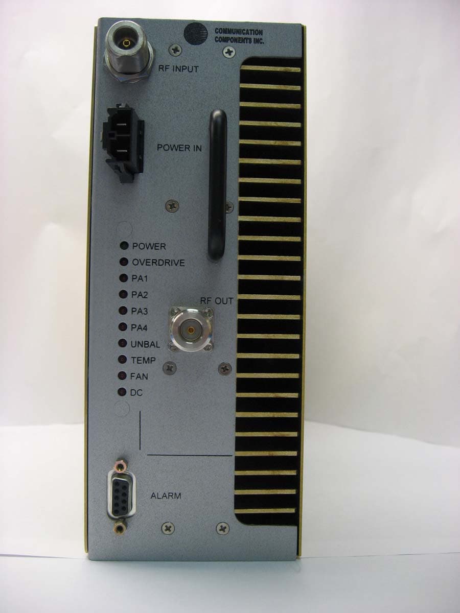
Click to zoom
Application Details
- Equipment Class
- AMP - Amplifier
- Date of Grant
- May 07, 2007
- Application Purpose
- Original Equipment
- Date of Application
- May 06, 2007
- Equipment Note
- PCS Band Multi Carrier Cell Extender
- Frequency Range
- 1931.25000000 - 1988.75000000
- Company
- Communication Components Inc
- Country
- United States
Documents & Files
Document Text
Text extracted from the exhibit documents filed with the FCC. Open a document above to read the original.
Users Manual
Communication Components, Inc. 89 Leuning Street Phone: 201-342-3338 South Hackensack, NJ 07606 Fax: 201-342-3339 PCS Band Multi Carrier Cell Extender CCI Model Number CE-1819-125MC-XXXX USER’S GUIDE Product Description: Communication Components, Inc. PCS CDMA Multi-carrier Cell Extender improves the performance of CDMA Base Stations (BTS) in indoor and outdoor locations, allowing for cost efficient implementation of high capacity radio networks. By increasing both the downlink power and receive sensitivity, CCI’s Cell Extender increases the overall coverage area and improves the performance of the site. Operation Description: CCI’s Multi-channel CDMA Cell Extender is designed to improve overall site performance by boosting both forward and reverse link parameters in a balanced manner. The system is designed to provide 125 Watts of usable CDMA output power per sector antenna (63 W per sector antenna for Canada) and can serve up to three sectors with two feeder antennas per sector. As such, a CE-1819- 125MC system used in six-carrier sector with 3 carriers per antenna can delivers 40 W per carrier (21 W per carrier for Canada). • CCI supplies Cell Extender cabinet that requires a dual 30A 208/240V breaker and two batteries for backup purposes. RF Connection Cell Extender cabinet must be bolted to the frame. • Connect Cell Extender input Tx/Rx and Rx ports (connectors type N located on the connectors plate inside of the main cabinet) with DO and D1 ports of BTS in the proper sector using two DIN-N jumpers. • Connect Cell Extender output Tx/Rx and Rx ports (Bias-T blocks with DIN connectors located on the connectors plate inside of the main cabinet) with Tx/Rx and Rx ports of Main Lines of the proper sector using two DIN-DIN jumpers. AC Connection • 20A Breakers must be installed in the main electrical box (or A-box). • 3-conductor AC-wire gage 12-14 must be run through metal conduit to the electrical junction box inside of the CCI Cell Extender cabinet. The entry point to this junction box is from the bottom of the cabinet via a corrugated shield. • Run a standard 6 gauge grounding wire from the site’s main grounding bar (Bus-bar in the A-box) to the CCI Cell Extender cabinet and secure it to the electrical junction box inside the cabinet. • Run Alarm cable through 1” conduit to the alarm card in BTS. Site technician will make actual connection. • Install the batteries: a. Place the batteries in the bottom of the cabinet b. Use the short jumper to connect the positive terminal of one battery to the negative terminal of the other battery. c. Cover the battery terminals with the supplied terminal boots. • Confirm proper electrical connection a. Turn off all breakers on PSU modules located in the Cell Extender cabinet; b. Turn on breakers in the main electrical box (A-box) c. Confirm that the green Power LED on PSU’s turn on. Setting the RF Output Power on the CE-1819-125MC-XXXxX Cell Extender The RF output power is adjustable on the Cell Extender. Use Gain Control Block that contains a set of the input signal attenuators. The user must adjust the RF input power to the Cell Extender connecting the proper pad such that the combined RF output power level of any number of the individual carriers does not exceed the levels shown below in order for the RF output spectral emissions to be compliant with the FCC spurious emissions limit of -13 dBm outside of the assigned frequency block. These levels must not exceed Channel Center Frequency (MHz) Maximum RF 0utput (Watt)* Maximum RF 0utput for Canada (Watt) 1930-1990 125 63 This equipment complies with Part 24 of the FCC rules. Any changes or modifications not expressly approved by the manufacturer could void the user's authority to operate the equipment. In order to comply with FCC rules for RF exposure, it must be observed that the antenna connected to this equipment be fixed on an outdoor structure and that it must have a minimum separation distance of 10 meters between it and any person. In accordance with Industry Canada RSS-131, the manufacturer's rated output power of this equipment is for single carrier operation. For situations when multiple carrier signals are present, the rating would have to be reduced by 3.5 dB, especially where the output signal is re-radiated and can cause interference to adjacent band users. This power reduction is to be by means of input power or gain reduction and not by an attenuator at the output of the device. PCS block filters must be installed to achieve compliance with part 24 spurious emission limits. Filters are manufactured by Clearcomm Technologies, part number CCFA-174- XX . Connect the output filter port marked “BTS “ with the port on By-Pass module marked “To BTS Duplexer”. Connect the filter port marked “ANT” to the By-Pass module port marked “ From ANT Duplexer”. Connect the filter port marked “AMP OUT” with corresponding attenuator port on Gain Control module. Connect filter port marked “AMP IN” to the Amplifier module port marked “ RF OUT”. * With External Tower Mounted Amplifier * Reverse Link Forward Link PCS Operating Range 1850-1910MHz 1930-1990 MHz Nominal 20 dB Bandwidth 60 MHz 39.27 MHz PCS band specific filters AD, BE, FC AD, BE, FC Nominal Pass-Band Gain 12 dB max Adjustable to 13.94 dB max System Noise Figure: 1.5.0 dB Max. System Group Delay: 180 nanosecond Max Pass Band Ripple: +/-0.5 dB Max. Output Third Order IM3 @ 1.98 MHz 0ffset: -55 dBc/30 kHz 1 dB Compression Point: +15 dBm Min. +58.5 dBm Typ. Input /Output VSWR: 1.5:1 Max. 1.5:1 Max. Up-Link-Down-Link Isolation 80 dB By-Pass Insertion Loss 0.5 dB for ground level unit, 0.3 dB for tower top unit Nominal Mean Output Power: 125 W ; 63 W for Canada Input and Output Impedance 50 Ohm Power Supply Voltage: 220 VAC Power Consumption: 1.0 KW Max per sector Dimensions 12”L x 5.5” W x 3”D -tower unit 77”H x 24”W x 21”D - ground level unit Enclosure NEMA 3R Weather Proof Cabinet Connectors Input from BTS –type N, F; output to hard lines -7 /1…
Text truncated - open the document above for the full version.
Block Diagram
RF Input (BTS Tx + Rx) RF Output (ANT Tx + Rx) CE-1819-125MC Amplifier DD-1819 Dual Duplexer Communication Components, Inc. 89 Leuning Street Phone: 201-342-3338 South Hackensack, NJ 07606 Fax: 201-342-3339 BTS Tx Input Tx Output CE-1819-125MC Block Diagram
Cover Letter(s)
Federal Communications Commission 7435 Oakland Mills Road Columbia, MD 21046 USA Authority to Act as Agent to the Federal Communications Commission On our behalf, I appoint Nemko USA, Inc. to act as agent in the preparation of this application for equipment authorization to the Federal Communications Commission. I certify that submitted Exhibits properly describe the device or system for which equipment authorization is sought. I also certify that each unit manufactured, imported or marketed, as defined in the Commission's regulations will have affixed to it a label identical to that submitted for approval with this application. APPLICANT ANTI-DRUG ABUSE CERTIFICATION: In signing this letter, Applicant certifies that, in the case of an individual applicant, he or she is not subject to a denial of federal benefits, that includes FCC benefits, pursuant to Section 5301 of the Anti-Drug Abuse Act of 1988, 21 U.S.C. 853(a), or, in the case of a non- individual applicant (e.g. corporation, partnership or other unincorporated association), no party to the application is subject to a denial of federal benefits, that includes FCC benefits, pursuant to that section. For the definition of a "party" for these purposes, see 47 CFR 1.2002(b). Dated this 22 nd Day of January 2007 Agency agreement expiration date: By: Dennis Nathan Title: President Telephone: (201) 342-3338 Applicant: Communication Components Inc. COMMUNICATION COMPONENTS INC Extending Wireless Coverage 89 Leuning Street Phone: 201-342-3338 2 nd Floor Fax: 201-342-3339 South Hackensack, NJ 07606 www.cciproducts.com
Cover Letter(s)
Communication Components, Inc. 89 Leuning Street Phone: 201-342-3338 South Hackensack, NJ 07606 Fax: 201-342-3339 01/22/07 Equipment Authorization Division Federal Communications Commission 7435 Oakland Mills Road Columbia, MD 21046 FCC ID: NT3CE-1819-125MC Product Name: PCS CDMA 125W Multi-Channel Cell Booster Request for Confidentiality Pursuant to Sections 0.457 and 0.459 of the commissions rules, we hereby request that the following documents be held confidential: • CE1819125schem.pdf (Schematics) • CE1819125parts.pdf (Parts Lists) • Internal Photos.pdf These materials contain trade secrets and proprietary information that is not customarily released to the public. The product is generally installed in secure locations which are not accessible to the general public. The product is only serviceable by Communications Components personnel or a factory-trained and licensed representative. The public disclosure of this information might be harmful to the company and provide unjustified benefits to our competitors. We respectfully request that this information remains confidential for a period of no less than 10 years. Dated this 22 Day of January 20 07 By: Dennis Nathan Signature Printed Title: President On behalf of: Communication Components Inc.
External Photos
CE-1819-125MC Amplifier and DD-1819 Filter Connections CE-1819-125-MC Front Panel CE-1819-125MC Rear Panel CE-1819-125MC Left Side CE-1819-125 Right Side CE-1819-125MC Top View CE-1819-125MC Bottom View DD-1819 Front View DD-1819-XX Side View
ID Label/Location Info
MODEL # CE-1819-125MC IC: 5629A-CE1819MC FCC ID: NT3CE-1819-125MC
ID Label/Location Info
Location of label
Operational Description
COMMUNICATION COMPONENTS INC Extending Wireless Coverage Multi-Carrier CDMA Cell Extender CE-1819-125MC Operational Description Introduction Communication Components, Inc. PCS CDMA Multi-carrier Cell Extender improves the performance of CDMA Base Stations (BTS) in indoor and outdoor locations, allowing for cost efficient implementation of high capacity radio networks. By increasing both the downlink power and receive sensitivity, CCI’s Cell Extender increases the overall coverage area and improves the performance of the site. The CE-1819-125MC provides up to 125 Watts of combined CDMA output power per feeder line/antenna. Technical Description CCI’s Multi-channel CDMA Cell Extender is designed to improve overall site performance by boosting both forward and reverse link parameters in a balanced manner. The system is designed to provide 125 Watts of usable CDMA output power per sector antenna and can serve up to three sectors with two feeder antennas per sector. As such, a CE-1819-125MC system used in six carrier sector with 3 carriers per antenna can delivers 40 W per carrier. The CE-1819-125MC was specifically designed for very simple interface with macro and mini base stations without any need of retrofitting the original BTS equipment and can be used with any BTS manufacturer equipment. The system can be pad mounted at any convenient location and H-frame or wall mounted when site space is limited. The Cell Extender system consists of two major blocks that can be easily connected during the initial installation of the BTS or as a retrofit to an operational BTS. The tower top amplifier (TTA) unit is mounted at the top of the tower next to the antennas and is responsible for improving the reverse (uplink) signal from mobile users and increasing the receive sensitivity of the BTS. The TTA is housed in a moisture proof NEMA 4X enclosure and contains low noise receive amplifiers and duplexers. The TTA is powered via DC power that is coupled onto the center conductor of the coax line. It also communicates TTA operational and alarm status from three multi-carrier sectors via the coax line to the main cabinet alarm system. The Ground Level Unit (GLU) is an outdoor cabinet designed to serve up to three sectors with up to six CDMA carriers per sector. Each sector section consists of high power Duplexers, multi-channel power amplifiers, gain control and bypass circuitry which is activated in case of failure of any critical component of the system. Fig. 1 shows block-diagram of the typical multi-carrier Cell Extender. As one can see, the duplexed signal from one of the BTS terminals that contains transmit and received signals is connected to the input terminal of the Cell Extender. After that signal is unduplexed and the Forward Link power is amplified by the power amplifier of the Cell Extender. Amplified signal is reduplexed with Reversed Link signal and sent to the one of the sector antennas. The gain control module controls the level of the BTS Downlink signal that is driving the Power Amplifier, and by changing the input attenuator value one can set the system gain. Similar RF signal processing is done on the second BTS terminal, if there are active carriers on that output. Fig.1 Multi-carrier Cell Extender Block Diagram. One sector serving two active antennas is shown. Po we r Su l SECTOR MODULE PA DUPLEXER Rx TX ANT DUPLEXER Rx TX BTS BTS Tx, Rx Tx , Rx PA DUPLEXER Rx TX ANT DUPLEXER Rx TX BTS Bias-T Bias-T DC DC 3 Carriers Sector Antennas LNA DUPLEXER Rx Tx A DUPLEXER Rx Tx LNA DUPLEXER Rx Tx A DUPLEXER Rx Tx TTATTA 3 Carriers Multi-Carrier Cell Extender U p to six carriers per sector. Ground Level Tower Level 125 W Combined 125 W Combine d Fig.2. Typical installation diagram for three-sector site. Decreasing the Noise Figure of the BTS at the antenna terminals utilizing low noise Tower Top Amplifiers also enhances the Reverse Link signals. These amplifiers have Noise Figure as low as 1.5 dB, and by installing them at the antenna terminals the Minimum Discernable signal can be decreased by three to six dB depending on the tower cable losses. Typical installation diagram for three-sector system is shown in Fig.2 Sector αSector βSector γ LN A LN A LN A LN A BTS Cell Extender FL Amps LN A LN A Multi-Carrier Cell Extender. Single 3-sector Ground Cabinet Installation Fig 3. Functional blocks of the Cell Extender. The system operational blocks assembly and interconnections is shown in Fig. 3. The major blocks include power amplifier block, dual duplexer block, gain control block, power supply block, and by-pass block. Signal from BTS enters the by-pass module input terminal and directed to duplexer module. After unduplexing the Forward Link signal is connected to High Power amplifier and Reverse Link signal is passed for reduplexing with very low insertion loss. The combined duplexed signal with amplified Forward Link power and Reverse Link traffic is connected to the by-pass module and than send to the antenna. By-pass module eliminates hard failure from the operation of the Cell Extender by connecting the input of the BTS to the output of Cell Extender and by-passing all other modules in case of the AC power failure or PA failure. If the Forward Link signal is amplified by six dB and the Reversed Link sensitivity is improved also by six dB, the balanced link budget improvement is achieved. Fig. 4 shows electrical and mechanical specifications for Cellular and PCS band Cell Extenders. CDMA Cell Extenders can operate in Cellular and PCS bands mounted in a single cabinet. Reverse Link TMA’s have typical Noise Figure of 1.5 dB. Forward Link power amplifiers in PCS band have combined power of 125 W. Power amplifiers in Cellular band available with 125 W of combined power for one to two carrier sites and with 200 W for two to four carrier sites. Implementation of CCI Cell Extenders can significantly decrease the required cell count in the coverage cluster, improved service in “cold spots”, alleviate…
Text truncated - open the document above for the full version.
Parts List/Tune Up Info
DC Voltage and Currents into final PA stage Voltage to PA: +28 Vdc Current in PA: +23 Amps at 125W composite CDMA output power
Test Report
Nemko Test Report No.: 6L0346RUS1 rev2 Applicant: Communication Components, Inc. 89 Leuning Street Second Floor Hackensack, NJ 07606 Equipment Under Test: CE-1819-125MC In Accordance With: FCC Part 24, Subpart E Tested By: Nemko USA Inc. 802 N. Kealy Lewisville, Texas 75057-3136 TESTED BY: DATE: Feb 1, 2007 Kevin Rose, Wireless Engineer APPROVED BY: DATE: Feb 1, 2007 David Light, Senior Wireless Engineer Total Number of Pages: 32 Nemko USA Inc. FCC PART 24, SUBPART E BROADBAND PCS REPEATERS EQUIPMENT: CE-1819-125MC Test Report Number 6L0346RUS1 rev 2 Page 2 of 32 Table of Contents SECTION 1. SUMMARY OF TEST RESULTS 3 SECTION 2. GENERAL EQUIPMENT SPECIFICATION 5 SECTION 3. RF POWER OUTPUT 7 SECTION 4. OCCUPIED BANDWIDTH 8 SECTION 5. SPURIOUS EMISSIONS AT ANTENNA TERMINALS 11 SECTION 6. FIELD STRENGTH OF SPURIOUS 20 SECTION 7. TEST EQUIPMENT LIST 22 ANNEX A - TEST DETAILS 23 ANNEX B - TEST DIAGRAMS 29 Nemko USA Inc. FCC PART 24, SUBPART E BROADBAND PCS REPEATERS EQUIPMENT: CE-1819-125MC Test Report Number 6L0346RUS1 rev 2 Page 3 of 32 Section 1. Summary of Test Results Manufacturer : Communication Components, Inc. Model No.: CE-1819-125MC Serial No.: None General: All measurements are traceable to national standards. These tests were conducted on a sample of the equipment for the purpose of demonstrating compliance with FCC Part 24, Subpart E. New Submission Production Unit Class II Permissive Change Pre-Production Unit THIS TEST REPORT RELATES ONLY TO THE ITEM(S) TESTED. THE FOLLOWING DEVIATIONS FROM, ADDITIONS TO, OR EXCLUSIONS FROM THE TEST SPECIFICATIONS HAVE BEEN MADE. See “ Summary of Test Data”. Nemko USA Inc. authorizes the above named company to reproduce this report provided it is reproduced in its entirety and for use by the company’s employees only. Any use which a third party makes of this report, or any reliance on or decisions to be made based on it, are the responsibility of such third parties. Nemko USA Inc. accepts no responsibility for damages, if any, suffered by any third party as a result of decisions made or actions based on this report. This report applies only to the items tested. Nemko USA Inc. FCC PART 24, SUBPART E BROADBAND PCS REPEATERS EQUIPMENT: CE-1819-125MC Test Report Number 6L0346RUS1 rev 2 Page 4 of 32 Summary Of Test Data NAME OF TEST PARA. NO. SPEC. RESULT RF Power Output 24.232 125W Complies Occupied Bandwidth Not defined Input/Output Complies Spurious Emissions at Antenna Terminals 24.238(a) -13 dBm Complies Field Strength of Spurious Emissions 24.238(a) -13 dBm Complies Frequency Stability 24.235 N/A N/A Footnotes: (1) Modulation characteristics were not tested since the E.U.T. amplifies but does not produce a modulated waveform. Measurement uncertainty for each test configuration is expressed to 95% probability. Nemko USA Inc. FCC PART 24, SUBPART E BROADBAND PCS REPEATERS EQUIPMENT: CE-1819-125MC Test Report Number 6L0346RUS1 rev 2 Page 5 of 32 Section 2. General Equipment Specification Supply Voltage Input: 28 Vdc Frequency Bands: Downlink: Block A : 1930 – 1945 MHz Block D : 1945 – 1950 MHz Block B : 1950 – 1965 MHz Block E : 1965 – 1970 MHz Block F : 1970 – 1975 MHz Block C : 1975 – 1990 MHz Operating Frequency of Test Sample: 1931.25 to 1988.75 MHz Frequency Bands: Uplink: Block A : 1850 – 1865 MHz Block B : 1865 – 1870 MHz Block C : 1870 – 1885 MHz Block D : 1885 – 1890 MHz Block E : 1890 – 1895 MHz Block F : 1895 – 1910 MHz CDMA GSM EDGE (F9W) (GXW) (G7W) Type of Modulation and Designator: Output Impedance: 50 ohms Per channel:NA W RF Output (Rated): Uplink Total:NA W Per channel:62.5 W RF Output (Rated): Downlink Total:125 W F1-F1 F1-F2 N/A Frequency Translation: Software Duplexer Fullband Band Selection: Note – This amplifier was tested using PCS block filters that must be used when installed to achieve compliance for spurious emissions. Nemko USA Inc. FCC PART 24, SUBPART E BROADBAND PCS REPEATERS EQUIPMENT: CE-1819-125MC Test Report Number 6L0346RUS1 rev 2 Page 6 of 32 Description of Operation The device is a 125-Watt base station amplifier operating in the PCS band used with CDMA signals. System Diagram Base station Filter AMP antenna Nemko USA Inc. FCC PART 24, SUBPART E BROADBAND PCS REPEATERS EQUIPMENT: CE-1819-125MC Test Report Number 6L0346RUS1 rev 2 Page 7 of 32 Section 3. RF Power Output NAME OF TEST: RF Power Output PARA. NO.: 2.1046 TESTED BY: Kevin Rose DATE: 12/06/2006 Test Results: Complies. Measurement Data: Modulation Type Single Channel Output Power (dBm) Two channel Output Power (dBm) Composite Output Power (dBm) Uplink CDMA N/A N/A N/A Downlink CDMA 51 48dBm/ Carrier 51 This device was tested at +/- 15% input power with no variation in output power. Analyzer Settings: RBW=VBW=3 MHz – Peak detector Equipment Used: 1036-1529-1185-1054-1058 Measurement Uncertainty: +/- 1.7 dB Temperature: 22 °C Relative Humidity: 40 % Nemko USA Inc. FCC PART 24, SUBPART E BROADBAND PCS REPEATERS EQUIPMENT: CE-1819-125MC Test Report Number 6L0346RUS1 rev 2 Page 8 of 32 Section 4. Occupied Bandwidth NAME OF TEST: Occupied Bandwidth PARA. NO.: 2.1049 TESTED BY: Kevin Rose DATE: 12/06/2006 Test Results: Complies. Test Data: See attached plot(s). Equipment Used: 1036-1529-1185-1054-1058 Measurement Uncertainty: +/- 1*10 -7 ppm Temperature: 22 °C Relative Humidity: 40 % Nemko USA Inc. FCC PART 24, SUBPART E BROADBAND PCS REPEATERS EQUIPMENT: CE-1819-125MC Test Report Number 6L0346RUS1 rev 2 Page 9 of 32 Test Data – Occupied Bandwidth Input Nemko USA Inc. FCC PART 24, SUBPART E BROADBAND PCS REPEATERS EQUIPMENT: CE-1819-125MC Test Report Number 6L0346RUS1 rev 2 Page 10 of 32 Test Data – Occupied Bandwidth Output Nemko USA Inc. FCC PART 24, SUBPART E BROADBAND PCS REPEATERS EQUIPMENT: CE-1819-125MC Test Report Number 6L0346RUS1 rev 2 Page 11 of 32 Section 5. Spurious Emissions at Antenna Terminals NAME OF TEST: Spurious Emissions @ Antenna Terminals PARA. NO.: 2.1051 TESTED BY: Kevin Rose DATE: 10/26/2006 Test Results: Complies. Test Data: See at…
Text truncated - open the document above for the full version.
Contact Information
Applicant
Dennis Nathan(President)
Technical Contact
Non-Technical Contact
Nemko DallasChristine Taylor
[email protected]972-436-9600
Test Firm
Nemko Dallas, Inc.Michael Cantwell
Technical Specifications
| # | Rule Parts | Frequency Range | Power Output | Emission | Tolerance |
|---|---|---|---|---|---|
| 1 | 24 | 1.93 GHz - 1.99 GHz | 125 W | F9W | Amp |
Other Applications from Communication Components Inc
NT3SERRFU8W
Mar 09, 2020SiriusXM SDAR Fiber Repeater
Equipment Class
BOS - All other signal boosters other than 20.21/90.219
NT3SCB8501WA
Jun 24, 2014Amplifier
Equipment Class
AMP - Amplifier
NT3MCPA2100125
Apr 19, 2011HIGH EFFICIENCY MCPA
Equipment Class
AMP - Amplifier
NT3DAB1819125G2
Jul 28, 2010PCS GSM/EDGE 125W Dual Amplifier Booster
Equipment Class
AMP - Amplifier
NT3CE-1819-10G2
Jul 03, 2007PCS Multi-Channel Cell Extender
Equipment Class
AMP - Amplifier