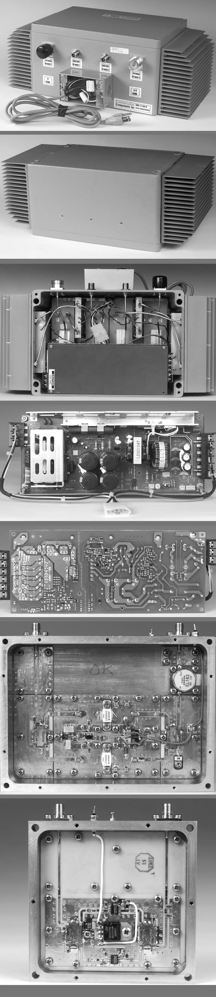
NT3CE-1819-20Single Channel Amplifier
Communication Components Inc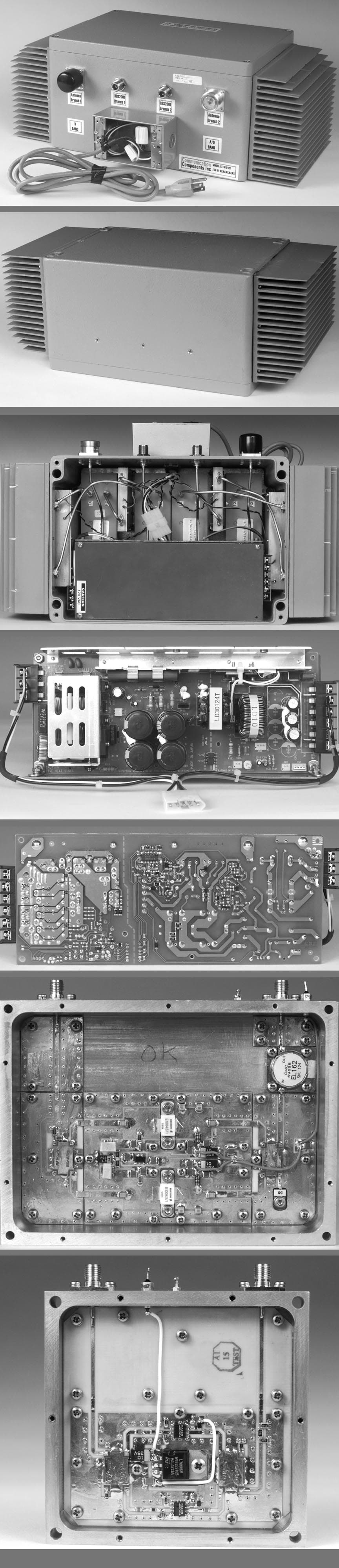
Click to zoom
Application Details
- Equipment Class
- PCB - PCS Licensed Transmitter
- Date of Grant
- Apr 18, 1999
- Application Purpose
- Original Equipment
- Date of Application
- Feb 01, 1999
- Equipment Note
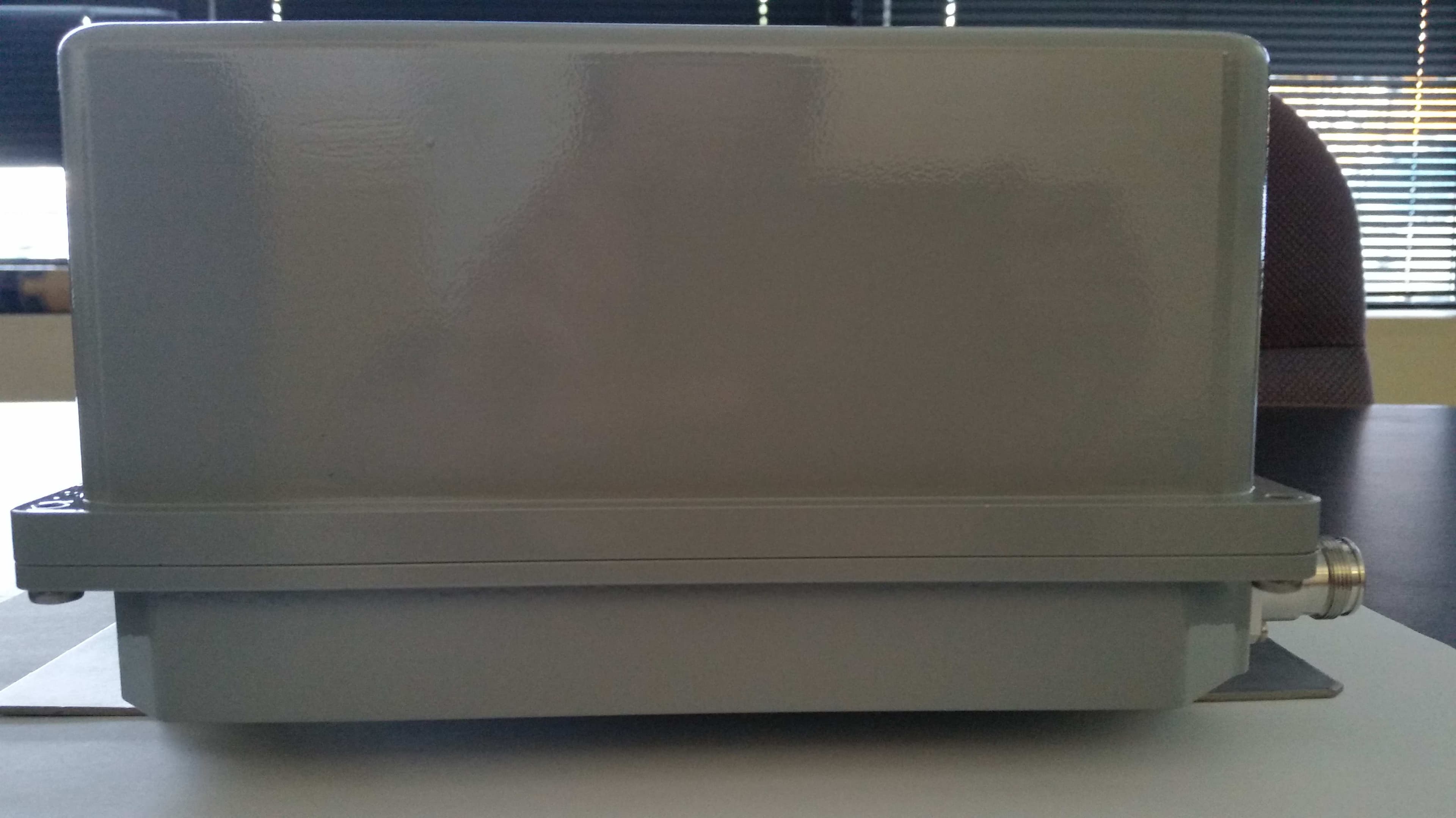
- Single Channel Amplifier
- Frequency Range
- 1930.40000000 - 1964.60000000
- Company
- Communication Components Inc
- Country
- United States
Documents & Files
Document Text
Text extracted from the exhibit documents filed with the FCC. Open a document above to read the original.
Users Manual
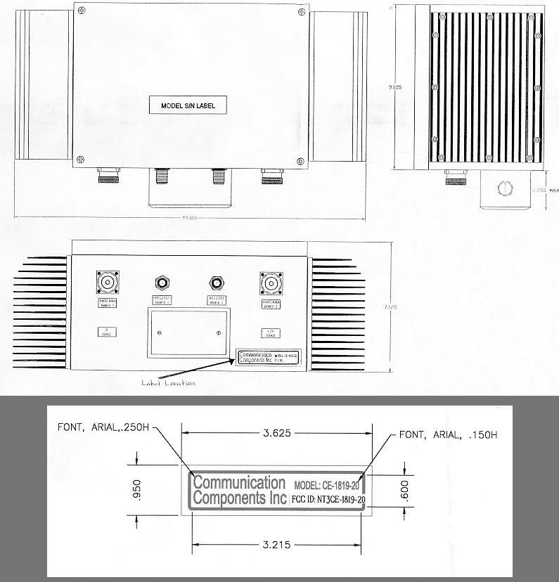
Communication Components Inc. Communication Components Inc.Communication Components Inc. Communication Components Inc. Communication Components Inc. Communication Components Inc.Communication Components Inc. Communication Components Inc. Communi cati on Components I nc. 299 Forest Avenue Paramus, NJ 07652 TEL: 201-265-8882FAX: 201-265-8922 Cell Extender for Cell Extender forCell Extender for Cell Extender for Ericsson RBS 2301 Ericsson RBS 2301Ericsson RBS 2301 Ericsson RBS 2301 Micro Base Stations Micro Base StationsMicro Base Stations Micro Base Stations RBS 2301 Cell Extender BLOCK DIAGRAM Rx/Tx DUPLEXER Rx BPF Tx BPF Rx/Tx DUPLEXER Rx BPF Tx BPF LNA Monitor/ Alarm (optional) 20 W PA Rx/Tx DUPLEXER Rx BPF Tx BPF Rx/Tx DUPLEXER Rx BPF Tx BPF LNA 20 W PA Power Supply To Antenna To RBS 2301 BIAS-T (optional) BIAS-T (optional) Communication Components Inc. Communication Components Inc.Communication Components Inc. Communication Components Inc. Communication Components Inc. Communication Components Inc.Communication Components Inc. Communication Components Inc. 299 Forest Avenue Tel: 201 265-8882 Paramus, NJ 07652Fax: 201 265-8922 CE-1819-20 Cell Extender CE-1819-20 Cell ExtenderCE-1819-20 Cell Extender CE-1819-20 Cell Extender System Specification System SpecificationSystem Specification System Specification General Information: Communication Component Inc.’s Cell Extender products are designed to extend the range and coverage area of Ericsson RBS 2301 Micro Base Stations in all GSM PCS applications. The Cell Extender boosts the output power of the RBS 2301 to match the levels of conventional Base Stations such as the RBS-2000 allowing for cost efficient implementation of high capacity radio networks. It also provides low-noise amplification of the receive signal to improve system sensitivity and to maintain a balanced link of the transmit and receive signals. The Cell Extender is easy to install, requires no maintenance, and is fully compatible with Ericsson Base Station equipment. The Cell Extender offers the maximum installation flexibility by allowing the RBS2301 to be physically distanced from the antenna and mounting structure. This overcomes the key key installation drawback of the RBS2301 which requires both a T1 connection and an AC connection on the mounting structure. Three installation options are available: • Configuration 1 - The CE-1819-20 can be mounted on the same mounting structure directly underneath the Micro Base Station. This option is ideal when an existing RBS2301 site is being upgraded with a Cell Extender or when both AC and T1 connections are available on the mounting structure. • Configuration 2 - The RBS2301 is installed at ground level or indoors and the Cell Extender is mounted on the mounting structure, in close proximity to the antenna. This configuration is ideal for environments where AC lines and T1-connections are not easily available on the mounting structure or when it is desired to keep the RBS2301 indoors. For this configuration, the Cell Extender should be ordered with the Remote Power Option which includes a Bias-t and Remote Power Supply module to provide DC power to the Cell Extender over the Coax cable. • Configuration 3 - Both the RBS2301 and the Cell Extender are installed at the ground level or indoors. This is intended for applications where it is impractical to install any equipment other than the antenna on the mounting structure. Communication Components Inc. Communication Components Inc.Communication Components Inc. Communication Components Inc. Communication Components Inc. Communication Components Inc.Communication Components Inc. Communication Components Inc. 299 Forest Avenue Tel: 201 265-8882 Paramus, NJ 07652Fax: 201 265-8922 Cell Extender System Specification Description: The Cell Extender is specifically designed for compatibility with the Ericsson RBS 2301 Base Station Equipment and is ensured to maintain the integrity of the GSM signal amplification. This is achieved by utilizing state-of-the-art LDMOS technology for amplification, monolithic Gallium-Arsenide technology low noise receive particular emphasis on low system group delay to minimize Bit-Error-Rate (BER) of transmissions. The Cell Extender block consists of a single compact unit with four RF connectors single AC line for power. It is housed in a moisture proof NEMA 4X aluminum enclosure with integrated heat sinks and is suitable for either outdoor or indoor The Cell Extender is designed to boost both low power tranceivers (both cells) provided with RBS 2301. It contains redundant low noise amplifiers to boost the signals, redundant LDMOS-based high power amplifiers to boost the transmit signal, duplexers, an integrated power supply and alarm/control circuitry to monitor the the unit. The Cell Extender is powered by a conventional 110/220 VAC source or optionally DC-powered via the Coax cable using Remote Power O . Ordering Options: Model CE-1819-20 01: Single Channel 02: Monitoring 03: Remote Power Option (with internal AD: A & D Block Operation B: B Block Operation C: C Block Operation Communication Components Communication ComponentsCommunication Components Communication Components Communication Components Communication ComponentsCommunication Components Communication Components 299 Forest Ave.Tel: 201 265-8882 Paramus,NJ 07652Fax:201 265-8922 Cell Extender System Specification Electrical Specification Up-LinkDown-Link • Model CE-1819-20 A&D Block:1850-1870 MHz 1930-1950MHz • Model CE-1819-20 B Block:1870-1885 MHz 1950-1965MHz • Model CE-1819-20 C Block:1895-1910 MHz 1975-1990MHz • Downlink: • System Gain10 dB • Gain Flatness± 0.5 dB Max • Output20 Watts Min • 1 dB Compression 15 Watts Min • Input/Output1.5:1 Max • Up-link 90 dB Min • Uplink: • System Gain10 dB • Gain Flatness± 0.5 dB Max • Noise Figure:2.5 dB Max. • Output Third Order Intercept +31 dBm Min. • Input/Output1.5:1 Max • Down-link 90 dB Min • Operating 115/220VAC or 28VDC • Current1.3 A @ Mechanical …
Text truncated - open the document above for the full version.
Operational Description
CELL EXTENDER Description of Operation Fig. 1. Block Diagram General Information: Communication Component Inc.'s Cell Extender products are designed to extend the range and coverage area of Ericsson RBS 2301 Micro Base Stations in all GSM PCS applications. The Cell Extender boosts the output power and the sensitivity of the RBS 2301 to match the levels of conventional Base Stations such as RBS-2000 allowing for cost efficient implementation of high capacity radio networks. It also provides low noise Tx1 Rx PA LNA Tx1/RxA Tx2 Rx PA LNA Tx2/Rx amplification of the receive signals to improve system sensitivity and to maintain a balanced link of the transmit and receive signals. Description of Operation: Mechanical. The Cell Extender block consists of a single compact unit with four RF connectors and a single AC line for power. It is housed in a moisture proof NEMA 4X aluminum die-cast enclosure with integrated heat sinks and it is suitable for either indoor or outdoor installations. 99 Electrical. Electrical block-diagram is shown in Fig.1. Unit consists from two identical channels. In each channel the signal coming to Base Station port is split in to receive (Rx) and transmit (Tx) frequency bands. Tx and Rx signals are amplified in opposite directions and recombined at the antenna port. Power Amplifier has redundant gain blocks based on LDMOS technology for improved linearity. Low Noise Amplifiers for the return link have also redundant design utilizing monolithic circuits. Up-link and Down-link signals are isolated by means of high selectivity duplexers providing 90 dB isolation each. The Cell Extender is powered by a conventional 110/220 VAC source or can be optionally DC-powered via the coax cable using the Remote Power Option. Electrical Specification for each Channel System Gain...................................10 dB Gain Flatness.................................+/-0.5 dB Output Power..................................20 W VSWR..........................................1.5:1 Up/Down Link Isolation.....................90 dB Noise Figure...................................2.5 dB Operating Voltage............................115/220 VAC of 28 VDC Current Consumption.........................1.3 A @ 120 VAC
Parts List/Tune Up Info
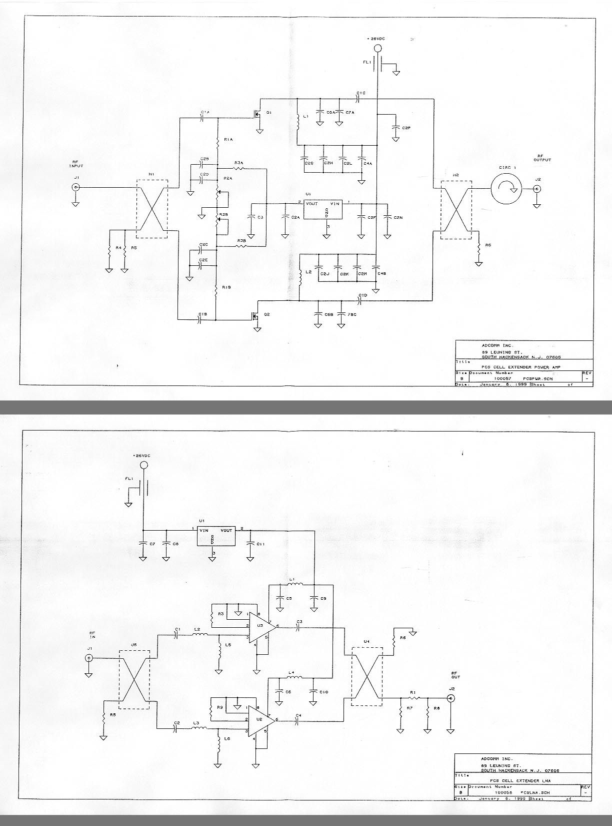
PART NUMBER: PL-100057 REVISION - SHEET 2 OF 5 ASSEMBLY TITLE: PCS BAND AMPLIFIER NEXT ASSY: 100059 SUB-ASSEMBLY CAGE CODE: 07TU2 TOP ASS 'Y NO: 100059 PROJE CT NO. 10058 ITEM REF DESIG. QTY PART/DOCUMENT # MFR. SPEC. DESCRIPITION NOTES 12 1 C201039 Rev - ADCOMM HOUSING,MACHINED AMPLIFIER 3 1 B201040 Rev - ADCOMM COVER, SHEET METAL AMPLIFIER 4 1 C201041 REV - ADCOMM HEATSINK, MACHINED AMPLIFIER 56 A1 1 B201166 Rev - ADCOMM PRINTED WIRING BOARD AMPLIFIER, MAIN BRD. 7 A2 1 B201167 Rev - ADCOMM PRINTED WIRING BOARD AMP, INPUT SPLITTER BRD. 8 A3 1 B201168 Rev - ADCOMM PRINTED WIRING BOARD AMP, OUTPUT SPLITTER BRD. 9 A4 1 B201169 Rev - ADCOMM PRINTED WIRING BOARD AMP, INPUT LAUNCH BRD. 10 A5 1 B201170 Rev - ADCOMM PRINTED WIRING BOARD AMP, OUTPUT LAUNCH BRD. 1112 J1,J2 2 132147 CONNEX CONNECTOR.SMA CCI (ALT) RSA3279 FEMALE 2 HOLE FLANGE 13 GRND 1 1595-2 KEYSTONE TERMINAL, TURRET #2-56 SINGLE TIER 14 FL1 1 54-779-001-102P MCI FEEDTHRU, CAPACITIVE 1000pfd #4-40 THD 15 PART NUMBER: PL-100057 REVISION - SHEET 3 OF 5 ASSEMBLY TITLE: PCS BAND AMPLIFIER NEXT ASSY: 100059 SUB-ASSEMBLY CAGE CODE: 07TU2 TOP ASS 'Y NO: 100059 PROJE CT NO. 10058 ITEM REF DESIG. QTY PART/DOCUMENT # MFR. SPEC. DESCRIPITION NOTES 1617 R1A,R1B,R4,R5 4 P100FCT-ND DIGI-KEY RESISTOR, CHIP 100 OHMS, 1206 Package 18 R2A,R2B 2 3214W-202ECT DIGI-KEY RESISTOR, POTENTIOMETER 2K OHM, SURFACE MOUNT 19 R3A,R3B 2 P150FCT-ND DIGI-KEY RESISTOR, CHIP 150 OHMS, 1206 Package 20 R6 1 RFP10-50TVC DIGI-KEY RESISTOR, FLANGE #6 THRU 50 OHM TERMINATION 21222324 C1A,C1B,C1C,C1D 4 C17AH470J4UXL DIELECTRIC CAPACITOR,CHIP SIDE LABS 47 pfd Mounting 25 C2A,C2B,C2C,C2D,C2E,C2 F 13 1210X7R104KL2AT ATC CAPACITOR,CHIP C2G,C2H,C2J,C2K,C2L,C2 M .1 ufd @ 50v 26 C2N 27 C3 1 PCS475CT-ND DIGI-KEY CAPACITOR,CHIP 4.7 ufd @ 10v 28 C4A,C4B 2 PCS610CT-ND DIGI-KEY CAPACITOR,CHIP 10 ufd @ 35v 29 C6A,C6B,C7A,C7B 4 C17AH1R5B4TXL DIELECTRIC CAPACITOR,CHIP LABS SAT (Starting Value 1.5 pfd) 30 C5A,C5B,C8A,C8B 4 C17AH???????? DIELECTRIC CAPACITOR,CHIP LABS SAT (Do Not Install) PART NUMBER: PL-100057 REVISION - SHEET 4 OF 5 ASSEMBLY TITLE: PCS BAND AMPLIFIER NEXT ASSY: 100059 SUB-ASSEMBLY CAGE CODE: 07TU2 TOP ASS 'Y 100059 PROJE CT NO. 10058 NO: ITEM REF DESIG. QTY PART/DOCUMENT # MFR. SPEC. DESCRIPITION NOTES 3132 CIRC1 1 EL162 CHANNEL CIRCULATOR MICROWAVE DROP-IN FLANGE MNT 3334 L1,L2 2 ADCOMM INDUCTOR, AIR COIL 6 TURNS, 24 AWG, .062 DIA. 3536 U1 1 NJM78L05UA DIGI-KEY REGULATOR,TO-220 Case 5 volts , 3738 Q1,Q2 2 PTF10043 RICHARDSON FET, POWER CCI 12 Watt 3940 H1,H2 2 SO3A1870N1 RF POWER HYBRID, 90' COMPONENTS 3 db, SURFACE MOUNT 41424344 45 PART NUMBER: PL-100057 REVISION SHEET 5 OF 5 ASSEMBLY TITLE: PCS BAND AMPLIFIER NEXT ASSY: 100059 SUB-ASSEMBLY CAGE CODE: 07TU2 TOP ASS 'Y NO: 100059 PROJE CT NO. 10058 ITEM REF DESIG. QTY PART/DOCUMENT # MFR. SPEC. DESCRIPITION NOTES 4647 MS51957-25 SCREW, PH PN HD S/S #6-32 THD x 1/4"(.250) LG 48 MS 35338-136 WASHER, SPLIT LOCK #6 S/S MEDIUM HELICAL 49 MS 51957-3 SCREW, PH PN HD S/S #2-56 THD x 1/4" (.250) LG 50 MS 35338-134 WASHER, SPLIT LOCK #2 S/S MEDIUM HELICAL 51 NAS620-C2 WASHER,FLAT S/S #2 REDUCED PATTERN 5253 54555657585960 PART NUMBER: PL-100058 REVISION A SHEET 2 OF 4 ASSEMBLY TITLE: PCS LOW NOISE AMP NEXT ASSY: 100059 SUB-ASSEMBLY CAGE CODE: 07TU2 TOP ASS 'Y NO: 100058 PROJE CT NO. 10058 ITEM REF DESIG. QTY PART/DOCUMENT # MFR. SPEC. DESCRIPITION NOTES 12 1 201042 REV A ADCOMM HOUSING,MACHINED LNA 3 1 201043 REV - ADCOMM COVER,SHEET METAL LNA 45 1 201054 REV - ADCOMM PRINTED CIRCUIT BOARD LNA 6789 C1THRUC6 6 805X102KL2AT ATC 805 CAPACITOR, CHIP SIZE 1000 pfd 10 C8,C9,C10 3 PCC103BNCT-ND DIGI-KEY 805 CAPACITOR, CHIP SIZE .01 ufd 11 C7 1 PCS610CT-ND DIGI-KEY CAPACITOR,CHIP TANT. 10 ufd @ 35volts 12 C11 1 12105C104KAT050 AVX 1210 CAPACITOR, CHIP SIZE .1ufd @ 50volts 131415 PART NUMBER: PL-100058 REVISION - SHEET 3 OF 4 ASSEMBLY TITLE: PCS LOW NOISE AMP NEXT ASSY: 100059 SUB-ASSEMBLY CAGE CODE: 07TU2 TOP ASS 'Y NO: 100058 PROJE CT NO. 10058 ITEM REF DESIG. QTY PART/DOCUMENT # MFR. SPEC. DESCRIPITION NOTES 1617 L1,L4 2 PCD1185CT-ND DIGI-KEY INDUCTOR,CHIP 12 nH 18 L2,L3 2 PCD1146CT-ND DIGI-KEY INDUCTOR,CHIP 3.9 nH 19 L5,L6 2 ADCOMM INDUCTOR, AIR COIL 4 TURNS, #32 AWG, .062 DIA. 20 21 R1 1 P18.0FCT-ND DIGI-KEY RESISTOR, CHIP SAT (Starting Value 18 Ohms) 22 R3,R9 2 P10.0CCT-ND DIGI-KEY RESISTOR, CHIP 10 OHMS 23 R5,R6 2 P51.1CCT-ND DIGI-KEY RESISTOR, CHIP 51.1 OHMS 24 R7,R8 2 P301FCT-ND DIGI-KEY RESISTOR, CHIP 301 OHMS 25 R2,R4 2 N/U NOT USED 2627 U1 1 NJM78M08FA-ND DIGI-KEY REGULATOR, TO-220F CASE 8 volt 500mA 28 U2,U3 2 AM50-0004 MACOM AMPLIFIER, 8 PIN DIP CCI Flat Pack 29 U4,U5 2 SO3A1870N1 HYBRID, 90' CCI 3db 30 PART NUMBER: PL-100058 REVISION - SHEET 4 OF 4 ASSEMBLY TITLE: PCS LOW NOISE AMP NEXT ASSY: 100059 SUB-ASSEMBLY CAGE CODE: 07TU2 TOP ASS 'Y NO: 100058 PROJE CT NO. 10058 ITEM REF DESIG. QTY PART/DOCUMENT # MFR. SPEC. DESCRIPITION NOTES 3132 J1,J2,J3 3 132147 CONNEX CONNECTOR.SMA CCI (ALT) RSA3279 FEMALE 2 HOLE FLANGE 33 GRND 1 1595-2 KEYSTONE TERMINAL, TURRET #2-56 SINGLE TIER 34 FL1 1 54-779-001-102P MCI FEEDTHRU, CAPACITIVE 1000pfd #4-40 THD 3536 MS51957-25 SCREW, PH PN HD S/S #6-32 THD x 1/4"(.250) LG 37 MS 35338-136 WASHER, SPLIT LOCK #6 S/S MEDIUM HELICAL 38 MS 51957-3 SCREW, PH PN HD S/S #2-56 THD x 1/4" (.250) LG 39 MS 35338-134 WASHER, SPLIT LOCK #2 S/S MEDIUM HELICAL 40 NAS620-C2 WASHER,FLAT S/S #2 REDUCED PATTERN 41424344 45 PART NUMBER: PL-100059 REVISION - SHEET 2 OF 5 ASSEMBLY TITLE: 10 W. CELL EXTENDER NEXT ASSY: CELLSITE PCS BAND TOP ASSY CAGE CODE: 07TU2 TOP ASS 'Y NO: 100059 PROJE CT NO. 10058 ITEM REF DESIG. QTY PART/DOCUMENT # MFR. SPEC. DESCRIPITION NOTES 12 1 201055 REV - ADCOMM ENCLOSURE, MACHINED, From CCI Hoffman P/N C-CA332318 3 1 201056 REV - ADCOMM BASE PLATE, MACHINED CCI From Hoffman P/N C- CAP3323 45 A1, A2 2 100057 REV - ADCOMM PWR AMPLIFIER,SUB-ASSY 6 2 201249 ADCOMM GASKET,PWR AMP .030 THK NEOPRENE 7 A3, A4 2 100058 REV - ADCOMM LNA, Low Noise Amplifier SUB ASSY 8 5ft UTC-141 CABLE, SEMIRIGI…
Text truncated - open the document above for the full version.
Schematics
.......... .......... GROSS WT. 34LB.
Schematics
Date: 09-17-98FCC ID: N7R-CM-AER Exhibit: Test Report Number of Pages: 27 WLI Project: 981525 TELECOMMUNICATION DIVISION CODE OF FEDERAL REGULATION PART 15 –INTENTIONAL RADIATORS SUBPART “C” – Paragraph 15.247 FREQUENCY HOPPING SPREAD SPECTRUM TRANSMITTERS Operating in the Frequency Band 2402-2478 MHz MEASUREMENT/TECHNICAL REPORT ON Product Name: MiniNet 2.4 Connection Manager Model: AIR I/O CM Applicant: Telxon Corporation 8302 New Trails Drive The Woodlands, TX 77381-4246 Tested by Request of: Telxon Corporation Test & Measurements Performed By: Wayne Langston Incorporated P.O. Box 1377; League City, TX 77574-1377 Tel: 281-337-6785; Fax: 281-337-7217 Email: [email protected] Test Results: The test results for this sample provided show that the EUT is [x], is not [] in compliance with the requirements of the CFR, Subpart C, Paragraph 15.247, Direct Sequence Spread Spectrum Transmitters operating in the Frequency Band 2402-2478 MHz. I certify that I am the technically qualified person responsible for preparation of the technical information contained in this application, and that it is complete and accurate to the best of my knowledge Tested By: Wayne LangstonDate: 09-17-98 Wayne Langston Incorporated authorized the above-named Applicant Company to reproduce this Report provided it is reproduced in its entirety. THIS REPORT MUST NOT BE USED TO CLAIM PRODUCT ENDORSEMENT BY NVLAP OR ANY AGENCY OF THE U.S. GOVERNMENT. Model: AIR I/O CMFCC ID: N7R-CM-AER Applicant: Telxon CorporationExhibit: Test Report Date: 09-17-98Page i of 27 WLI Project: 981525 TABLE OF CONTENTS Section 1 General Information ............................................................................................................................1 1.1 Description of Equipment Under Test..................................................................................................1 1.2 Test System Details....................................................................................................................................4 1.3 Related Submittals/Grant ...................................................................................................... 4 1.4 Test Methodology ........................................................................................................................................4 1.5 Test Facility..................................................................................................................................................4 1.6 Test Sample...................................................................................................................................................5 1.7 Test Results ........................................................................................................................... 5 1.8 Modifications ........................................................................................................................ 6 1.9 Justification ........................................................................................................................... 6 1.10 EUT Operation Condition ................................................................................................... 6 1.11 Special Accessories ............................................................................................................. 6 Section 2: Product Labeling ............................................................................................................ 6 2.1 Information to the User ............................................................................................................. 6 Section 3 Test System Measurements .............................................................................................7 3.1 Measurement of Terminal Interference Voltage Labeling ................................................... 7 3.1.1 Terminal Interference Voltage Measurement Data ........................................................... 7 3.2 Measurement of Radiated Interference Field Strength......................................................... 7 3.2.1 Radiated Interference Field Strength Measurement Data.................................................. 7 Section 4 Measurement Uncertainty ..................................................................................................................7 Section 5 General Measurement Conditions ................................................................................ 10 5.1 Ambient Emanations ......................................................................................................... 10 5.2 Test Configuration............................................................................................................. 10 5.3 Firmware ........................................................................................................................... 11 5.4 Exercise Software.............................................................................................................. 11 5.5 Ground Plane..........................................................................................11 5.6 Power Input ........................................................................................................................ 11 5.7 Climate Condition .............................................................................................................. 11 Section 6 Method of Measurement of Terminal Interference Voltage.......................................... 11 6.1 Method of Measurement of Radiated Disturbances Field Strength ................................... 11 6.1.1 Aerial ............................................................................................................................... 12 6.1.2 Aerial-to-test Unit Distance ............................................................................................ 12 6.1.3 Aerial-to-Ground Distance ...................................................…
Text truncated - open the document above for the full version.
Test Report
Master: ktlPT24RPTR Date: October 8, 1998 KTL Test Report:8R01087 Applicant:Communication Components Inc. 299 Forest Avenue Paramus, NJ 07652 Equipment Under Test:PCS Signal Enhancer (E.U.T.) FCC ID:NT3CE-1819-20 In Accordance With:FCC Part 24, Subpart E Broadband PCS Repeaters Tested By:KTL Ottawa Inc. 3325 River Road, R.R. 5 Ottawa, Ontario K1V 1H2 Authorized By: _____________________________________ W. Waterhouse, RF Engineering Lab Manager Date:_____________________________________ Total Number of Pages:43 KTL Ottawa FCC PART 24, SUBPART E BROADBAND PCS REPEATERS PROJECT NO.: 8R01087 EQUIPMENT: PCS Signal Enhancer FCC ID: NT3CE-1819-20 Page 2 of 33 Table of Contents Section 1. Summary of Test Results General Summary of Test Data Section 2. General Equipment Specification Specifications Description of Modifications for Class II Permissive Change Modifications Made During Testing Theory of Operation System Diagram Section 3. RF Power Output Test Results Measurement Data Power Over Bandwidth Graphs Section 4. Occupied Bandwidth Occupied Bandwidth (CDMA) Test Results CDMA Input and Output Graphs Occupied Bandwidth (GSM) Test Results GSM Input and Output Graphs Occupied Bandwidth (NADC) Test Results NADC Input and Output Graphs Section 5. Spurious Emissions at Antenna Terminals Test Results Test Data Graphs Section 6. Field Strength of Spurious Test Results Test Data Test Data - Radiated Emissions - Uplink Test Data - Radiated Emissions - Downlink Photographs of Test Setup Pre-Scan Data KTL Ottawa FCC PART 24, SUBPART E BROADBAND PCS REPEATERS PROJECT NO.: 8R01087 EQUIPMENT: PCS Signal Enhancer FCC ID: NT3CE-1819-20 Page 3 of 33 Table of Contents, continued Section 7. Frequency Stability Test Results Measurement Data Graphs Section 8. Test Equipment List Annex A - Test Methodologies RF Power Output Occupied Bandwidth (CDMA) Occupied Bandwidth (GSM) Occupied Bandwidth (NADC) Spurious Emission at Antenna Terminals Field Strength of Spurious Frequency Stability Annex B - Test Diagrams R.F. Power Output Occupied Bandwidth Spurious Emissions at Antenna Terminals Field Strength of Spurious Frequency Stability KTL Ottawa FCC PART 24, SUBPART E BROADBAND PCS REPEATERS PROJECT NO.: 8R01087 EQUIPMENT: PCS Signal Enhancer FCC ID: NT3CE-1819-20 Page 4 of 33 Section 1.Summary of Test Results Manufacturer:Communication Components Inc. Model No.:CE-1819-20 Serial No.:2380 General: All measurements are traceable to national standards. These tests were conducted on a sample of the equipment for the purpose of demonstrating compliance with FCC Part 24, Subpart E. New SubmissionProduction Unit Class II Permissive ChangePre-Production Unit Equipment Code THIS TEST REPORT RELATES ONLY TO THE ITEM(S) TESTED. THE FOLLOWING DEVIATIONS FROM, ADDITIONS TO, OR EXCLUSIONS FROM THE TEST SPECIFICATIONS HAVE BEEN MADE. See “ Summary of Test Data”. NVLAP LAB CODE: 100351-0 TESTED BY: _____________________________________ DATE: ___________________ Kevin Carr, Technologist TECHNICAL REVIEW: ____________________________ DATE: ___________________ Tom Tidwell, Wireless Group Manager KTL Ottawa Inc. authorizes the above named company to reproduce this report provided it is reproduced in its entirety and for use by the company’s employees only. Any use which a third party makes of this report, or any reliance on or decisions to be made based on it, are the responsibility of such third parties. KTL Ottawa Inc. accepts no responsibility for damages, if any, suffered by any third party as a result of decisions made or actions based on this report. This report applies only to the items tested. KTL Ottawa FCC PART 24, SUBPART E BROADBAND PCS REPEATERS PROJECT NO.: 8R01087 EQUIPMENT: PCS Signal Enhancer FCC ID: NT3CE-1819-20 Page 5 of 33 Summary Of Test Data NAME OF TESTPARA. NO.SPEC.MEAS.RESULT RF Power Output24.232100W20WComplies Occupied Bandwidth (GSM)24.238Input/OutputPlotComplies Spurious Emissions at Antenna Terminals 24.238(a)-13 dBm-13.33Complies Field Strength of Spurious Emissions24.238(a)-13 dBm E.I.R.P. TableComplies Frequency Stability24.235N/AN/AN/A Footnotes For N/A’s: F1-F1 Test Conditions: Temperature: 20 °C Humidity:25 % KTL Ottawa FCC PART 24, SUBPART E BROADBAND PCS REPEATERS PROJECT NO.: 8R01087 EQUIPMENT: PCS Signal Enhancer FCC ID: NT3CE-1819-20 Page 6 of 33 Section 2.General Equipment Specification Supply Voltage Input: 120 VAC, 60 Hz Frequency Range:Downlink: B-Band, 1950 / 1964.95 MHz A/D-Band, 1930 / 1949.95 MHz Frequency Range:Uplink: Not Applicable 20 dB Bandwidth: Not Applicable Type of Modulation and CDMAGSMNADC Designator: (F9W)(GXW)(DXW) AGC Threshold: Not Applicable Output Impedance: 50 ohm Gain: 13 dB Nominal Max Input Power: +30 dBm RF Output (Rated):Single: 43.0 dBm Frequency Translation: F1-F1F1-F2N/A Band Selection: SoftwareDuplexer Change Fullband Coverage KTL Ottawa FCC PART 24, SUBPART E BROADBAND PCS REPEATERS PROJECT NO.: 8R01087 EQUIPMENT: PCS Signal Enhancer FCC ID: NT3CE-1819-20 Page 7 of 33 Description of Modifications For Class II Permissive Change KTL Ottawa FCC PART 24, SUBPART E BROADBAND PCS REPEATERS PROJECT NO.: 8R01087 EQUIPMENT: PCS Signal Enhancer FCC ID: NT3CE-1819-20 Page 8 of 33 Modifications Made During Testing KTL Ottawa FCC PART 24, SUBPART E BROADBAND PCS REPEATERS PROJECT NO.: 8R01087 EQUIPMENT: PCS Signal Enhancer FCC ID: NT3CE-1819-20 Page 9 of 33 Theory of Operation The CE-1819-20 is a bi-directional amplifier that can be mounted on the same mounting structure directly underneath the micro-based station. The cell extender is specifically designed for compatibility with the Ericsson RBS 2301 base station. The E.U.T. is designed to boost both low power transceivers (both cells) provided with RBS 2301. The unit contains redundant low noise amps, and higher power amps, it also contains an integrated power supply and alarm/control circuitry to monitor the unit. The uplink direction is hard wired to the base station. System Diagram Tx1 Tx2 Rx Rx PA PA LNA LNA Tx1/RxA Tx…
Text truncated - open the document above for the full version.
Contact Information
Applicant
Dennis Nathan(President)
Technical Contact
Non-Technical Contact
KTL OTTAWAJOANNE A BACKES
[email protected]1-800-563-6336
Test Firm
Nemko Canada Inc.Stuart Beck
Technical Specifications
| # | Rule Parts | Frequency Range | Power Output | Emission |
|---|---|---|---|---|
| 1 | 24E | 1.93 GHz - 1.96 GHz | 20 W | GXW |
Other Applications from Communication Components Inc
NT3SERRFU8W
Mar 09, 2020SiriusXM SDAR Fiber Repeater
Equipment Class
BOS - All other signal boosters other than 20.21/90.219
NT3SCB8501WA
Jun 24, 2014Amplifier
Equipment Class
AMP - Amplifier
NT3MCPA2100125
Apr 19, 2011HIGH EFFICIENCY MCPA
Equipment Class
AMP - Amplifier
NT3DAB1819125G2
Jul 28, 2010PCS GSM/EDGE 125W Dual Amplifier Booster
Equipment Class
AMP - Amplifier
NT3CE-1819-10G2
Jul 03, 2007PCS Multi-Channel Cell Extender
Equipment Class
AMP - Amplifier