NUL-9255WiFi Powerbolt Electronic Deadbolt
Spectrum Brands, Inc.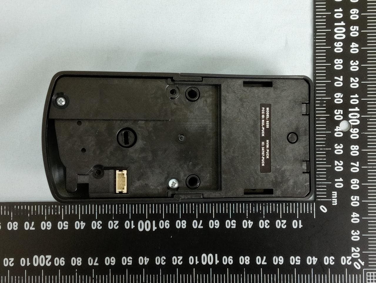
Click to zoom
Application Details
- Equipment Class
- DTS - Digital Transmission System
- Date of Grant
- Sep 21, 2026
- Application Purpose
- Original Equipment
- Equipment Note
- WiFi Powerbolt Electronic Deadbolt
- Frequency Range
- 2402.00000000 - 2480.00000000
- Company
- Spectrum Brands, Inc.
- Country
- United States
Documents & Files
Document Text
Text extracted from the exhibit documents filed with the FCC. Open a document above to read the original.
Users Manual
WiFi Powerbolt Electronic Deadbolt Installation and Reference Guide 57825-001 Rev 01 English ENGLISH | SPANISH | FRENCH Tap or Click for Alternative Languages Welcome to the Kwikset family! This guide will get you up and running with your new Powerbolt 255. If you have any issues, please visit our support center: kwikset.com/support or call us at 1-800-327-5625. Getting started For an inter active version of this installation guide, please download the Kwikset app: kwikset.com/app 1 Parts in the box ..................................................3 Required tools ....................................................4 Installation ............................................................5 Download the app ..........................................14 Reference guide ................................................16 Table of contents 2 Parts in the box Exterior Assembly Interior Assembly Interior Cover Latch Collar Strike 1 Step 53648 53648 Batteries 2Step 3 Required tools Phillips head screwdriver No electric drills Ruler Flat head screwdriver Mounting plate Keys 3 Step 52367 SmartKey™ tool 52502 Adapter ring 4 Installation If drilling a new door, use the supplied template and instructions available at: kwikset.com/doorprep Remove your existing deadbolt ! 1-3/8” to 1-3/4” (35mm - 44mm) 1-1/2” or 2-1/8” (38mm to 54mm) Note: Please contact customer service if door thickness exceeds 1-3/4 in for a thick door kit. 6 1 Install the latch B UP A If the rectangle shaped hole is not centered in the door hole, rotate the latch face to extend the latch. 53648 (2X) If your door is not chiseled, install the driv e-in collar. [OUTSIDE] UP is on top. Wood Block 1.Use a flathead screwdriver to remove latch face. 3. Install the drive-in collar to the latch. 4. Install latch to the door. 2. Twist and pull the collar off. 7 DOOR JAMB 53648 (2X) 2 Install the strike 1" (25mm) hole depth 8 Install the ext erior assembly 3 [OUTSIDE] Cable goes under the latch. A Remove adapter ring if bore hole measures 1-1/2” (38mm) diameter. 9 [INSIDE] Tighten the screws evenly. (2X) [INSIDE] Tighten the screws evenly. DO NOT over-tighten. Keep parallel to the door edge 52367 B C Route the cable through the center hole of the mounting plate, then push the cable down into the bottom hole. Insert the key and test the latch. If the bolt does not extend or retract smoothly, adjust the screws. Leave the bolt LOCKED/EXTENDED. Before You Continue Ensure the latch bolt is in the extended position. 10 Install the interior assembly 4 Remove the interior cover from the interior assembly. DO NOT install the batteries. Wait until Step 5. DO NOT remove the sticker from the turnpiece. Ensure the turnpiece remains in a vertical position. 11 Secure the interior assembly onto the mounting plate. Ensure latch bolt is extended. [INSIDE] D Ensure the flat blade fully engages with the turnpiece shaft. C B Connect the cable. Ensure a tight cable connection. Excess cable will sit inside the bottom of the interior housing. (2X) 52502 Ensure cable remains connected. Ensure the bolt is in the extended position. 12 Install batteries 5 With the door open, install the batt eries. NOTE: Lock must be installed on the door befor e inserting the batt eries. [INSIDE] Insert (4) AA batt eries (included) into the batt ery pack. Ensure correct polarity. Use new, non-rechargeable alkaline batteries only. B Remove sticker from the turnpiece. A 13 Download the Kwikset app & create an account to complete set up Complete your lock set up If this lock was prof es sionally installed (or installed by someone other than the homeowner), make sure this step is performed by the homeowner. kwikset.com/app Follow the instructions in the Kwikset app to complete lock setup. 15 Ref er ence Guide To lock your door, press the Kwikset logo button. The lock will play a tune, and the button will flash amber as the deadbolt extends. To unlock your door, enter the user code. The lock will play a tune, and the Kwikset logo button will flash green as the deadbolt retracts. LockingUnlocking 17 Re-key the lock to work with your existing key by following the SmartKey Re-key instructions. NOTE:If Aut o-Lock is enabled, remove the batteries befor e re-keying your lock. SmartKey Re-key 18 Amber: Locked Flashes Red 2x: Low Battery Flashes Red once: Invalid Credentials Gr een: Unlocked Exterior LED Indicators Flashes Red 15x: Lockout Red and Keypad flashes alternatively: Lock Jammed 19 Gr een Amber Slow Blinking: Unlocked Blinking: Low Batt ery Slow Blinking: Locked Red Int erior Status LED Indicators 20 Factory Reset will: •delete all access codes and associated schedule •reset lock settings to default •lock will show as offline in the Kwikset App •lock will be deactivated and will need to be set up as new Factory Reset should be used when: •you want to change the lock owner •you have lost your phone •you are troubleshooting the lock Factory Reset 1. Press and hold the Programming Button. 2. While still holding the Programming Button, insert the batteries. Continue holding the Programming Button for 30 seconds. Continue to the next page for additional steps. 21 3. After 30 seconds, the Status LED light will flash RED and lock will beep. Release the Programming Button. 5. SUCCESS: Lock will play a series of beeps, Status LED will flash GREEN, then pulsing BLUE. UNSUCCESSFUL: Lock will play a single-tone sound, Status LED light will flash RED. 4. Press the Programming Button again within 5 seconds. Status LED 22 Powerbolt 255 at a Glance ExteriorInterior (cover removed) Troubleshooting If you have an y issue s, please visit our support center: kwikset.com/support or call us at 1-800-327-5625. Status LED Programming Button Lock Button Number Buttons SmartKey Cylinder 23 Important Safeguards Regulatory Compliance 1.Read all instructions in their entirety. 2. Familiarize yourself with all warning and caution statements. 3. Remind all family members of safety precautions. 4. Always have access …
Text truncated - open the document above for the full version.
Users Manual
¡Bienvenido a la familia Kwikset! Esta guía te ayudará a ponerte en marcha con tu nuevo Powerbolt 255. Si tiene algún problema, visite nuestro centro de asistencia: kwikset.com/support o llame al 1-800-327-5625. Empezando Para obtener una versión interactiva de esta guía de instalación, descargue la aplicación Kwikset: kwikset.com/app 1 Tabla de contenidos Piezas en la caja ...............................................3 Herramientas necesarias ............................4 Instalación..........................................................5 Configuración completa de la cerradura ..............................................14 Guía de referencia ........................................16 2 Piezas en la caja Ensamble exteriorEnsamble interior Cubierta interior PestilloCuello Placa 1 Paso Baterías 2 Paso 53648 53648 3 Herramientas necesarias Destornillador Phillips No taladros eléctricos Regla Destornillador plano Placa de montaje Llaves 3 Paso 52367 Herramienta SmartKey™ 52502 Anillo adaptador 4 Instalación Retire el cerrojo existente ! 1-3/8” a 1-3/4” (35mm - 44mm) 1-1/2” a 2-1/8” (38mm to 54mm) Nota: Póngase en contacto con el servicio de atención al cliente si el grosor de la puerta supera los 1-3/4 pulgadas para solicitar un kit para puertas gruesas. Si perfora una puerta nueva, utilice la plantilla suministrada y las instrucciones disponibles en: kwikset.com/doorprep 6 1 Instale el pestillo B UP A Si el orificio en forma de rectángulo no está centrado en el orificio de la puerta, gire la cara del pestillo para extenderlo. 53648 (2X) Si su puerta no está cincelada, instale el collarín de entrada. [EXTERIOR] UP está en la cima. bloque de madera 7 1.Utilice un destornillador de punta plana para retirar la placa frontal del pestillo. 2. Gire y extraiga el collarín. 4. Instale el pestillo en la puerta. 3. Instale el collarín en el pestillo. Jamba de puerta 53648 (2X) 2 Instale la placa 1" (25 mm) profundidad del orificio 8 Instale el ensamble ext erior 3 [EXTERIOR] El cable pasa por debajo del pestillo. A Retire el anillo adaptador si el diámetro del orificio es de 1-1/2" (38 mm) 9 (2X) [INTERIOR] Apriete los tornillos de manera uniforme. NO apriete demasiado. Manténgase paralelo al borde de la puerta 52367 B C Pase el cable a través del orificio central de la placa de montaje, luego empuje el cable hacia abajo dentro del orificio inferior. Inserte la llave y pruebe el pestillo. Si el pestillo no se extiende o retrae suavemente, ajuste los tornillos. Deje el perno BLOQUEADO/EXTENDIDO y retire las llaves. 10 Antes de Continuar Asegúrese de que el pestillo esté en la posición extendida. Instale el ensamble interior 4 NO instale las baterías. Espere hasta el paso 5. Retire la cubierta interior del ensamble interior. 11 NO retire la etiqueta del eje interior. Asegúrese de que la pieza permanezca en posición vertical. Fije el conjunto interior a la placa de montaje. Asegúrese de que el pestillo esté extendido. [INTERIOR] D Asegúrese de que la hoja plana encaje completamente en el eje del mango giratorio. C B Conecte el cable. Asegúrese de que la conexión del cable esté bien ajustada. El cable sobrante quedará dentro de la parte inferior de la carcasa interior. (2X) 52502 Asegúrate de que el cable siga conectado. 12 Asegúrese de que el pestillo esté en posición extendida. Instale las baterías 5 Con la puerta abierta, instale el paquete de baterías. NOTA: Se debe instalar una cerradura en la puerta antes de insertar las baterías. [INTERIOR] 13 Inserte (4) baterías AA (incluidas) en el compartimento de las baterías. Asegúrese de la polaridad correcta. Utilice únicamente baterías alcalinas nuevas, no recargables. B Retire la etiqueta del eje interior. A Descargue la aplicación Kwikset y cree una cuenta para completar la configuración. Completa la configuración de tu cerradura. Si esta cerradura fue instalada por un profesional (o por alguien que no sea el propietario), asegúrese de que este paso lo realice el propietario. kwikset.com/app Siga las instrucciones de la aplicación Kwikset para completar la configuración de la cerradura. 15 Guía de referencia Para cerrar la puerta con llave, pulse el botón con el logotipo de Kwikset. La cerradura emitirá dos pitidos y el botón con el logotipo de Kwikset parpadeará en color ámbar mientras se extiende el cerrojo. Para desbloquear la puerta, introduzca el código de usuario. La cerradura emitirá dos pitidos y el botón con el logotipo de Kwikset parpadeará en verde mientras se retrae el cerrojo. BloqueoDesbloqueo 17 Vuelva a introducir la cerradura para que funcione con la llave existente siguiendo las instrucciones de SmartKey Re-key. NOTA: Si el bloqueo automático está activado, retire el batería antes de volver a teclear el bloqueo. SmartKey® Re-key 18 Ámbar: Bloqueado Luz intermitente Rojo 2x: Batería baja Parpadea Rojo una vez: Credenciales no válidas Verde: Desbloqueado Indicadores LED exteriores Luz intermitente Rojo 15x: Bloqueó El rojo y el teclado parpadean alternativamente: Cerradura atascada 19 Verde Ámbar Parpadeo lento: Desbloqueado Parpadeo: Batería baja Parpadeo lento: Bloqueado Rojo Indicadores LED de estado interior 20 El restablecimiento de fábrica: •Eliminar todos los códigos de acceso y el horario asociado •Restablecer la configuración de bloqueo a los valores predeterminados •La cerradura aparecerá como desconectada en la aplicación Kwikset •El bloqueo se desactivará y deberá configurarse como nuevo El restablecimiento de fábrica debe utilizarse cuando: •Quieres cambiar el propietario de la cerradura •Has perdido tu teléfono •Estás solucionando el problema del bloqueo Restablecimiento de fábrica 1. Mantenga pulsado el botón de programación. 2. Mientras mantiene pulsado el botón de programación, inserte las pilas. Siga manteniendo pulsado el botón de programación durante 30 segundos. Continúe en la página siguiente para ver los pasos adicionales. 21 3. Después de 30 segundos, el LED de estado parpadeará en ROJO y la cerradura emiti…
Text truncated - open the document above for the full version.
Users Manual
Pièces dans la boîte Assemblage extérieurAssemblage intérieur Couverture intérieure Loquet Collier Grève 1 Étape Piles 2 Étape 53648 53648 3 Outils nécessaires Tournevis cruciforme Pas de perceuses électriques Règle Tournevis à tête plate Plaque de montage Clés 3 Étape 52367 Outil SmartKey™ 52502 Bague d'adaptation 4 Installation Si vous percez une nouvelle porte, utilisez le gabarit fourni et les instructions disponibles à l'adresse suivante: kwikset.com/doorprep Retirez votre serrure à pêne dormant existante ! 1-3/8 po à 1-3/4 po (35mm - 44mm) 1-1/2 po à 2-1/8 po (38mm to 54mm) Remarque: Veuillez contacter le service clientèle si l'épaisseur de la porte dépasse 1-3/4 pouce pour obtenir un kit pour porte épaisse. 6 1 Installez le loquet B UP A Si le trou rectangulaire n'est pas centré dans l'ouverture de la porte, tournez la face du loquet pour allonger le loquet. 53648 (2X) Si votre porte n'est pas ciselée, installez le collier d'entraînement. [EXTÉRIEUR] UP est en tête. 7 1.Utilisez un tournevis à tête plate pour retirer la têtière. 2. Tournez l’anneau et tirez dessus pour le retirer. 4. Installez le pêne dans la porte. 3. Installez l’anneau encastré sur le pêne. B UP A Si le trou rectangulaire n'est pas centré dans l'ouverture de la porte, tournez la face du loquet pour allonger le loquet. 53648 (2X) UP est en tête. bloc de bois DOOR JAMB 53648 (2X) 2 Installez la gâche 1 po (25 mm) profondeur du trou 8 Installez l'ensemble extérieur 3 [EXTÉRIEUR] Le câble passe sous le loquet. A Retirez la bague d'adaptation si le diamètre du trou est de 1-1/2 po (38 mm). 9 (2X) [INTÉRIEUR] Serrez les vis uniformément. NE SERREZ PAS TROP FORT. Restez parallèle au bord de la porte 52367 B C Faites passer le câble dans le trou central de la plaque de montage, puis poussez-le vers le bas dans le trou inférieur. Insérez la clé et testez le loquet. Si le loquet ne sort pas ou ne rentre pas correctement, ajustez les vis. Laissez le verrou VERROUILLÉ/SORTIE, et retirez les clés. Avant de Continuer Assurez-vous que le pêne demi-tour est en position sortie. 10 Installez l'ensemble intérieur 4 Retirez le couvercle intérieur de l'ensemble intérieur. 11 NO instale las baterías. Espere hasta el paso 5. NE RETIREZ PAS l’autocollant du taquet. Veillez à ce que le taquet reste en position verticale. Fixez l'ensemble intérieur sur la plaque de montage. Assurez-vous que le pêne demi-tour est sorti. [INTÉRIEUR] D Assurez-vous que la lame plate s'engage complètement dans l' arbre de la pièce tournante. C B Branchez le câble. Assurez-vous que le câble est bien connecté. Le câble excédentaire se trouvera à l'intérieur du fond du boîtier intérieur. (2X) 52502 S'assurer que le câble reste connecté. 12 Assurez-vous que le pêne est en position déployée. Install batteries 5 Avec la porte ouverte, installez les piles. REMARQUE: le verrou doit être installé sur la porte avant d'insérer les piles. [INTÉRIEUR] 13 Insérez 4 piles AA incluses dans le bloc-piles. Assurez-vous de respecter la polarité. Utilisez uniquement des piles alcalines neuves et non rechargeables B Retirez l’autocollant du taquet. A Téléchargez l'application Kwikset et créez un compte pour terminer la configuration Si cette serrure a été installée par un professionnel (ou par une personne autre que le propriétaire), assurez-vous que cette étape est effectuée par le propriétaire. kwi kset.com/app Terminez la configuration de votre serrure Suivez les instructions dans l'application Kwikset pour terminer la configuration de la serrure. 15 Guide de référence Pour verrouiller votre porte, appuyez sur le bouton du logo Kwikset. La serrure émettra deux bips et le bouton du logo Kwikset clignotera en orange lorsque le pêne dormant s'étendra. Pour déverrouiller votre porte, entrez le code utilisateur. La serrure émettra deux bips et le bouton du logo Kwikset clignotera en vert lorsque le pêne dormant se rétractera. VerrouillageDéverrouillage 17 Recléer la serrure pour qu'elle fonctionne avec votre clé existante en suivant les instructions de recléage SmartKey . REMARQUE: Si la fonction de verrouillage automatique est activée, retirez le bloc-piles avant de recléer votre serrure. Recléage Smartkey® 18 Ambre: Verrouillé Clignotements Rouge 2x: Batterie faible Flashes Red once: Identifiants invalides Vert: Déverrouillé Indicateurs LED extérieurs Clignotements Rouge 15x: Verrouillage Le voyant rouge et le clavier clignotent alternativement: Serrure bloquée 19 Vert Ambre Clignement lent: Déverrouillé Clignotement: Batterie faible Clignement lent: Verrouillé Rouge Indicateurs LED intérieur 20 La réinitialisation d'usine: •Supprimer tous les codes d'accès et le calendrier associé •Réinitialiser les paramètres de verrouillage aux valeurs par défaut •La serrure apparaîtra comme hors ligne dans l'application Kwikset •Le verrouillage sera désactivé et devra être configuré comme nouveau La réinitialisation d'usine doit être utilisée dans les cas suivant: •vous souhaitez changer le propriétaire du verrou •vous avez perdu votre téléphone •vous dépanniez la serrure Réinitialisation d'usine 1. Appuyez sur le bouton Programmation et maintenez-le enfoncé. 2. Tout en maintenant le bouton de programmation enfoncé, insérez les piles. Continuez à maintenir le bouton de programmation enfoncé pendant 30 secondes. Passez à la page suivante pour les étapes supplémentaires. 21 3. Au bout de 30 secondes, la LED d'état clignotera en ROUGE et le verrou émettra un bip. Relâchez le bouton de programmation. 5. SUCCÈS: Le verrou émettra une série de bips, la LED d'état clignotera en VERT, puis en BLEU. ÉCHEC: Le verrou émettra un bip sonore unique et le voyant d'état LED clignotera en ROUGE. 4. Appuyez à nouveau sur le bouton de programmation dans les 5 secondes. Voyant d'état 22 255 en bref ExtérieurIntérieur (couverture retirée) Voyant d'état Programmation Bouton Dépannage Si vous avez des problèmes, s’il vous plaît visitez notre centre de soutien: kwikset.com/support ou appelez-nous au 1-800-327-5625…
Text truncated - open the document above for the full version.
Attestation Statements
Rev 1/26/2023 Public Federal Communications Commission Authorization and Evaluation Division 7435 Oakland Mills Road Columbia, MD 21046 USA Date: 9/12/2026 Ref: Attestation Statements Part 2.911(d)(5)(i) Filing FCC ID: NUL-9255 [Spectrum Brands, Inc.] (“the applicant”) certifies that the equipment for which authorization is sought is not “covered” equipment prohibited from receiving an equipment authorization pursuant to section 2.903 of the FCC rules. [Spectrum Brands, Inc.] (“the applicant”) certifies that the equipment for which authorization is sought does not include cybersecurity or anti-virus software produced or provided by Kaspersky Lab, Inc. or any of its successors and assignees, including equipment with integrated Kaspersky Lab, Inc. (or any of its successors and assignees) cybersecurity or anti-virus software pursuant to DA-24-886 and KDB 986446 D01 Covered Equipment Guidance section B(2a). Device is inherently compliant based on hardware limitations or software controls. or A Software Bill of Materials (SBOM) is provided to the TCB for review, and The end-user or third parties cannot install additional software on this device. Sincerely, (Applicant signature) Thuan Nguyen Rev 1/26/2023 Public Federal Communications Commission Authorization and Evaluation Division 7435 Oakland Mills Road Columbia, MD 21046 USA Date: 9/12/2026 Ref: Attestation Statements Part 2.911(d)(5)(ii) Filing FCC ID: NUL-9255 [Spectrum Brands, Inc.] (“the applicant”) certifies that, as of the date of the filing of the application, the applicant is not identified on the Covered List (as a specifically named entity or any of its subsidiaries or affiliates) as an entity producing “covered” equipment. Sincerely, (Applicant signature) Thuan Nguyen
Attestation Statements
Rev 1/26/2023 Public Federal Communications Commission Authorization and Evaluation Division 7435 Oakland Mills Road Columbia, MD 21046 USA Date: 2026/9/4 Ref: Attestation Statements Part 2.911(d)(7) Filing FCC ID: NUL-9 255 [Spectrum Brands, Inc.] (“the applicant”) certifies that, as of the date of the filing of the application, [Spectrum Brands, Inc.] is our designated U.S. agent for service of process for the above referenced FCC ID. [Spectrum Brands, Inc.] accepts to maintain an agent for no less than one year after the grantee has terminated all marketing and importation or the conclusion of any Commission-related proceeding involving the equipment. [Spectrum Brands, Inc.] accepts, as of the date of the filing of the application, the obligation of the designated U.S. agent for service of process for the above referenced FCC ID. Designated U.S. Agent Information: Name: Spectrum Brands, Inc. Address: 19701 Da Vinci Foothill Ranch California 92610 USA. Contact Person: Thuan Nguyen Tel.: 1-949-672-4452 Email : [email protected] FRN: 00037031481 Sincerely, For Spectrum Brands, Inc. (as Applicant and Designated U.S. Agent) Signature Printed Name: Thuan Nguyen Title: Assoc. Principal Engineer, RF Electronics
Cover Letter(s)
MS-0044715 Page 1 of 1 Revision 1 Public Date: 2026/9/12 Federal Communications Commission Equipment Authorization Branch 7435 Oakland Mills Road, Columbia, MD 21046, USA Subject: Confidentiality Request for FCC ID: NUL-9255 Pursuant to FCC 47 CFR 0.457(d), the applicant requests that a part of the subject FCC/IC application be held confidential. Type of Confidentiality Requested Exhibit Short Term Permanent Block Diagrams Short Term n/a External Photo Short Term Permanent Internal Photos *** Short Term Permanent Operation Description/Theory of Operation Short Term Permanent Schematics Permanent Permanent Test Setup*** Permanent Permanent User’s Manual*** Short Term Permanent Part List Spectrum Brands, Inc. has spent substantial effort in developing this product and it is one of the first of its kind in industry. Having the subject information easily available to "competition" would negate the advantage they have achieved by developing this product. Not protecting the details of the design will result in financial hardship. Permanent Confidentiality: The applicant requests the exhibits listed above as permanently confidential be permanently withheld from public review due to materials that contain trade secrets and proprietary information not customarily released to the public. (*** Exceptional case for Permanent Confidentiality for these Exhibits by PAG only) Short-Term Confidentiality: The applicant requests the exhibits selected above as short term confidential be withheld from public view for a period of 180 days from the date of the Grant of Equipment Authorization and prior to marketing. This is to avoid premature release of sensitive information prior to marketing or release of the product to the public. Applicant is also aware that they are responsible to notify TUV Rheinland in the event information regarding the product or the product is made available to the public. TUV Rheinland will then release the documents listed above for public disclosure pursuant to FCC Public Notice DA 04-1705. Sincerely, By: Thuan Nguyen / Assoc. Principal Engineer, RF Electronics (Signature) (Print name/Title) Tel: 9496724452 Email: [email protected]
Cover Letter(s)
Public Authority to Act as Agent Date: 2026/7/23 Federal Communications Commission Authorization and Evaluation Division 7435 Oakland Mills Road Columbia, MD 21046 USA To Whom It May Concern: I appoint TUV Taiwan / Jason Chang to act as our agent in the preparation of this application for equipment certification. I certify that submitted documents properly describe the device or system for which equipment certification is sought. I also certify that each unit manufactured, imported or marketed, as defined in the FCC or Industry Canada’s regulations will have affixed to it a label identical to that submitted for approval with this application. For instances where our authorized agent signs the application for certification on our behalf, I acknowledge that all responsibility for complying with the terms and conditions for Certification, as specified by TUV Rheinland Group, still resides with Spectrum Brands, Inc. / 19701 DaVinci Foothill Ranch California 92610 United States. For TCB applications, We certify that we are not subject to denial of federal benefits, that includes FCC benefits, pursuant to Section 5301 of the Anti-Drug Abuse Act of 1988, 21 U.S.C. 862. Further, no party, as defined in 47 CFR 1.2002 (b), to the application is subject to denial of federal benefits, that includes FCC benefits. Thank you, Agency Agreement Date: 2026/7/23 Agreement is valid for 12 months from the above date. By: Thuan Nguyen (Signature) (Print name) Assoc. Principal Engineer, RF Electronics 9496724452 (Title) (Telephone) Spectrum Brands, Inc. (Company Name)
External Photos
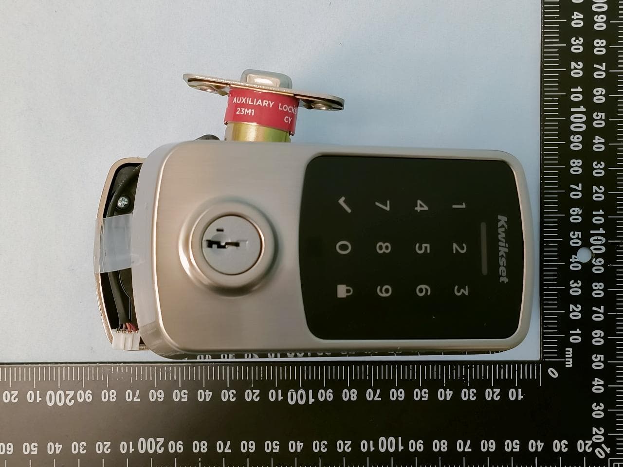
Appendix EP Photographs of EUT Page 1 of 17 CN26GHSR 001, CN261JQ8 001 CN2654LR 001 Product: WiFi Powerbolt Electronic Deadbolt Type Identification: 9255 Appendix EP Photographs of EUT Page 2 of 17 CN26GHSR 001, CN261JQ8 001 CN2654LR 001 Product: WiFi Powerbolt Electronic Deadbolt Type Identification: 9255 Appendix EP Photographs of EUT Page 3 of 17 CN26GHSR 001, CN261JQ8 001 CN2654LR 001 Product: WiFi Powerbolt Electronic Deadbolt Type Identification: 9255 Appendix EP Photographs of EUT Page 4 of 17 CN26GHSR 001, CN261JQ8 001 CN2654LR 001 Product: WiFi Powerbolt Electronic Deadbolt Type Identification: 9255 Appendix EP Photographs of EUT Page 5 of 17 CN26GHSR 001, CN261JQ8 001 CN2654LR 001 Product: WiFi Powerbolt Electronic Deadbolt Type Identification: 9255 Appendix EP Photographs of EUT Page 6 of 17 CN26GHSR 001, CN261JQ8 001 CN2654LR 001 Product: WiFi Powerbolt Electronic Deadbolt Type Identification: 9255 Appendix EP Photographs of EUT Page 7 of 17 CN26GHSR 001, CN261JQ8 001 CN2654LR 001 Product: WiFi Powerbolt Electronic Deadbolt Type Identification: 9255 Appendix EP Photographs of EUT Page 8 of 17 CN26GHSR 001, CN261JQ8 001 CN2654LR 001 Product: WiFi Powerbolt Electronic Deadbolt Type Identification: 9255 Appendix EP Photographs of EUT Page 9 of 17 CN26GHSR 001, CN261JQ8 001 CN2654LR 001 Product: WiFi Powerbolt Electronic Deadbolt Type Identification: 9255
ID Label/Location Info
Public FCC & IC sticker places Label location as illustration (Interior chassis backside) Dimension illustration:
Internal Photos
Appendix EP Photographs of EUT Page 10 of 17 CN26GHSR 001, CN261JQ8 001 CN2654LR 001 Product: WiFi Powerbolt Electronic Deadbolt Type Identification: 9255 Appendix EP Photographs of EUT Page 11 of 17 CN26GHSR 001, CN261JQ8 001 CN2654LR 001 Product: WiFi Powerbolt Electronic Deadbolt Type Identification: 9255 Appendix EP Photographs of EUT Page 12 of 17 CN26GHSR 001, CN261JQ8 001 CN2654LR 001 Product: WiFi Powerbolt Electronic Deadbolt Type Identification: 9255 Appendix EP Photographs of EUT Page 13 of 17 CN26GHSR 001, CN261JQ8 001 CN2654LR 001 Product: WiFi Powerbolt Electronic Deadbolt Type Identification: 9255 Antenna Appendix EP Photographs of EUT Page 14 of 17 CN26GHSR 001, CN261JQ8 001 CN2654LR 001 Product: WiFi Powerbolt Electronic Deadbolt Type Identification: 9255 Appendix EP Photographs of EUT Page 15 of 17 CN26GHSR 001, CN261JQ8 001 CN2654LR 001 Product: WiFi Powerbolt Electronic Deadbolt Type Identification: 9255 Appendix EP Photographs of EUT Page 16 of 17 CN26GHSR 001, CN261JQ8 001 CN2654LR 001 Product: WiFi Powerbolt Electronic Deadbolt Type Identification: 9255 Appendix EP Photographs of EUT Page 17 of 17 CN26GHSR 001, CN261JQ8 001 CN2654LR 001 Product: WiFi Powerbolt Electronic Deadbolt Type Identification: 9255
RF Exposure Info
Prü fbericht - Produkte Test Report - Products Prüfbericht-Nr.: Test report no.: CN2654LR 001 Auftrags-Nr.: Order no.: 48307048 Seite 1 von 11 Page 1 of 11 Kunden-Referenz-Nr.: Client reference no.: N/A Auftragsdatum: Order date: 2026-06-24 Auftraggeber: Client: Spectrum Brands, Inc. 19701 Da Vinci Foothill Ranch California 92610 USA. Prü fgegenstand: Test item: WiFi Powerbolt Electronic Deadbolt Bezeichnung / Typ-Nr.: Identification / Type no.: 9255 Auftrags-Inhalt: Order content: FCC Certification Prü fgrundlage: Test specification: IEEE Std C95.1 47 CFR §2.1091 47 CFR §1.1310 KDB 447498 D04 Wareneingangsdatum: Date of sample receipt: 2026-08-06 Prü fmuster-Nr.: Test sample no: A004358334-001 A004358334-002 Prü fzeitraum: Testing period: 2026-08-24 - 2026-09-04 Ort der Prü fung: Place of testing: TÜ V Rheinland Taiwan Ltd. New Taipei Branch Prü flaboratorium: Testing laboratory: TÜ V Rheinland Taiwan Ltd. Taipei Testing Laboratories Prü fergebnis*: Test result*: Pass zusammengestellt von: compiled by: Anderson Chiu genehmigt von: authorized by: Flight Hsieh Datum: Date: 2026-09-06 Ausstellungsdatum: Issue date: 2026-09-06 Stellung / Position: Senior Project Manager Stellung / Position: Project Engineer Sonstiges / Other: The output results refer to report no. CN26GHSR 001 and CN261JQ8 001. Zustand des Prü fgegenstandes bei Anlieferung: Condition of the test item at delivery: Prüfmuster vollständig und unbeschädigt Test item complete and undamaged * Legende: 1 = sehr gut 2 = gut 3 = befriedigend 4 = ausreichend 5 = mangelhaft P(ass) = entspricht o.g. Prüfgrundlage(n) F(ail) = entspricht nicht o.g. Prüfgrundlage(n) N/A = nicht anwendbar N/T = nicht getestet * Legend: 1 = very good 2 = good 3 = satisfactory 4 = sufficient 5 = poor P(ass) = passed a.m. test specification(s) F(ail) = failed a.m. test specification(s) N/A = not applicable N/T = not tested Dieser Prü fbericht bezieht sich nur auf das o.g. Prü fmuster und darf ohne Genehmigung der Prü fstelle nicht auszugsweise vervielfältigt werden. Dieser Bericht berechtigt nicht zur Verwendung eines Prü fzeichens. This test report only relates to the a. m. test sample. Without permission of the test center this test report is not permitted to be duplicated in extracts. This test report does not entitle to carry any test mark. TUV Rheinland Taiwan Ltd. 11F., No. 758, Sec. 4, Bade Rd., Taipei 105, Taiwan, R.O.C. Mail: [email protected] ∙ Web: www.tuv.com V101023GCNSR Prü fbericht - Produkte Test Report - Products…
Text truncated - open the document above for the full version.
Contact Information
Applicant
Thuan Nguyen
[email protected]Fax: 9496724776
Technical Contact
Spectrum Brands, Inc.Thuan Nguyen
19701 Da Vinci · Foothill Ranch, California, 92610 · United States
Test Firm
TUV Rheinland Taiwan Ltd. Taipei Testing Lab.Zeus Y.R. Chen
[email protected]Fax: 886-2-2172-1322
Technical Specifications
| # | Rule Parts | Frequency Range | Power Output |
|---|---|---|---|
| 1 | 15C | 2.40 GHz - 2.48 GHz | 9.89 mW |
| 2 | 15C | 2.41 GHz - 2.46 GHz | 112.46 mW |
Other Applications from Spectrum Brands, Inc.
NUL-9490
Aug 11, 2026WI-FI SMART LOCK
Equipment Class
DTS - Digital Transmission System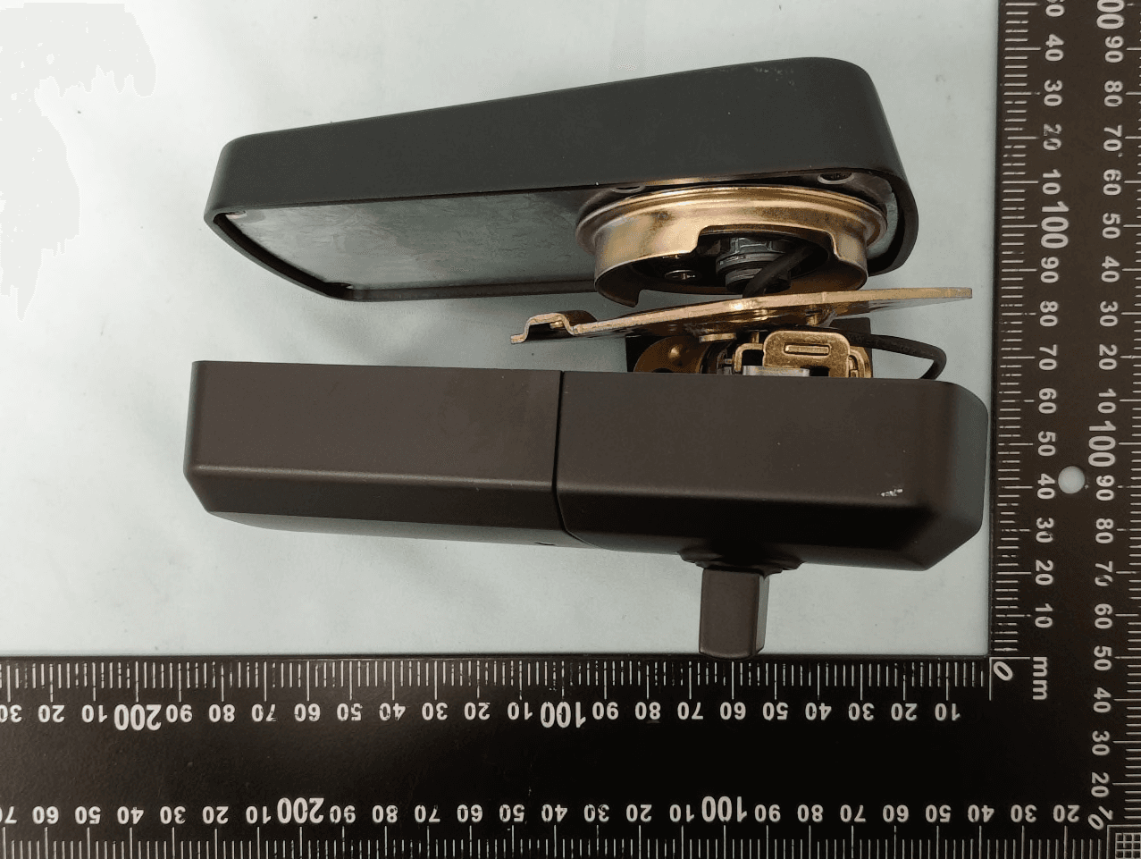
NUL-AURA2
Sep 30, 2025Aura Reach
Equipment Class
DTS - Digital Transmission System
NUL-UNT1
Jun 29, 2023Multifamily
Equipment Class
DTS - Digital Transmission System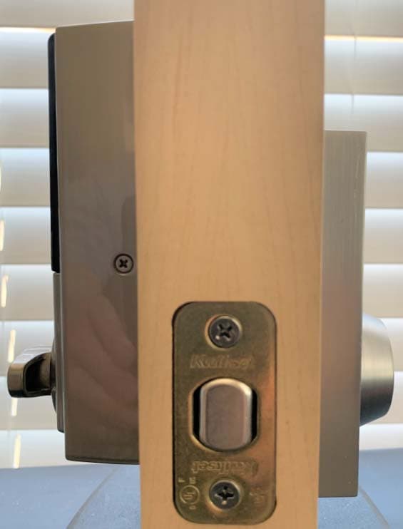
NUL450126VHC
Sep 21, 2020Z_Wave Plus Lock Version II
Equipment Class
DXT - Part 15 Low Power Transceiver, Rx Verified
NUL-924
Sep 17, 2015Router Plugin Unit
Equipment Class
DXT - Part 15 Low Power Transceiver, Rx Verified