NUW002EKO19Extender
EMS Technologies Inc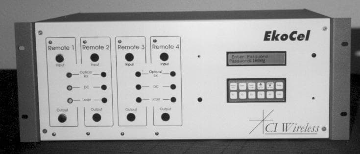
Click to zoom
Application Details
- Equipment Class
- AMP - Amplifier
- Date of Grant
- Oct 19, 1998
- Application Purpose
- Original Equipment
- Date of Application
- May 08, 1998
- Equipment Note
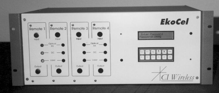
- Extender
- Frequency Range
- 1930.00000000 - 1965.00000000
- Company
- EMS Technologies Inc
- Country
- United States
Documents & Files
Document Text
Text extracted from the exhibit documents filed with the FCC. Open a document above to read the original.
Operational Description
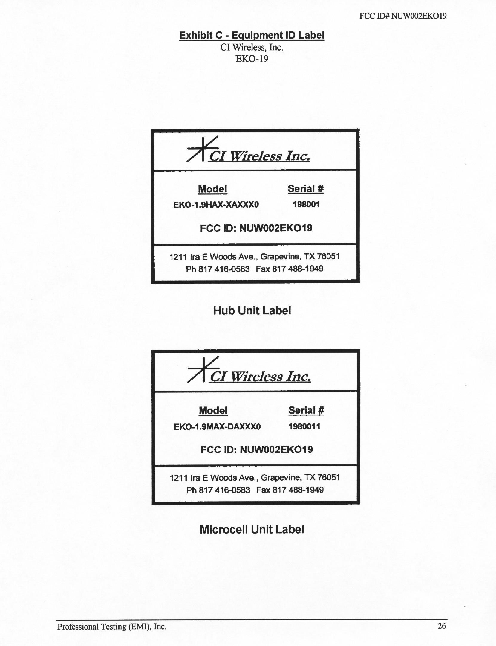
-FCC ID# NUW002EKO19 Professional Testing (EMI), Inc.1 Exhibit E - Measurement Report CI Wireless, Inc. EKO-19 FCC ID# NUW002EKO19 Professional Testing (EMI), Inc.2 Table of Contents Title Page .............................................................................................................................................................................. 1 Table of Contents ................................................................................................................................................................. 35 Certificate of Compliance .................................................................................................................................................... 36 1.0 Equipment Under Test (EUT) Description .................................................................................................................. 37 2.0 Power and Antenna Height Limits................................................................................................................................. 38 2.1 Test Procedure .............................................................................................................................................................. 38 2.2 Test Criteria................................................................................................................................................................... 38 2.3 Test Results ................................................................................................................................................................... 38 3.0 Frequency Stability ....................................................................................................................................................... 38 4.0 Modulation Characteristics ........................................................................................................................................... 38 5.0 Occupied Bandwidth..................................................................................................................................................... 38 6.0 Spurious Emissions at Antenna Terminals ................................................................................................................... 39 6.1 Test Procedure .............................................................................................................................................................. 39 6.2 Test Criteria................................................................................................................................................................... 39 6.3 Test Results ................................................................................................................................................................... 39 7.0 Field Strength of Spurious Emissions........................................................................................................................... 39 7.1 Test Procedure .............................................................................................................................................................. 39 7.2 Test Criteria................................................................................................................................................................... 39 7.3 Test Results ................................................................................................................................................................... 39 8.0 Signal Purity.................................................................................................................................................................. 40 8.1 Test Procedure .............................................................................................................................................................. 40 8.2 Test Criteria................................................................................................................................................................... 40 8.3 Test Results ................................................................................................................................................................... 40 9.0 List of Test Equipment.................................................................................................................................................. 40 Appendix A - Power Output Test Data................................................................................................................................ 42 Appendix B - Spurious Emissions at Antenna Terminals Test Data................................................................................... 43 Appendix C - Field Strength of Spurious Emissions Test Data .......................................................................................... 60 Appendix D - Signal Purity Test Data ................................................................................................................................. 72 Appendix E - Photographs ................................................................................................................................................... 80 FCC ID# NUW002EKO19 Professional Testing (EMI), Inc.3 Applicant:CI Wireless, Inc. Applicant’s Address:1211 Ira E. Woods Ave. Grapevine, TX 76051 Model:EKO-19 PCS extender Serial Number Hub198001 Serial Number Microcell:1980011 Project Number:98-385 Test Dates:April 8 through 9, 1998 I, Jeffrey A. Lenk, for Professional Testing (EMI), Inc., being familiar with the FCC rules and test procedures have reviewed the test setup, measurement data and this report. I believe them to be true and accurate. The CI Wireless Inc. EKO-19 PCS extender FCC ID: NUW002EKO was tested and found to be in compliance with FCC Parts 15 and 24 for Intentional Radiators. _________________________ Jeffrey A. Lenk President Certif…
Text truncated - open the document above for the full version.
Operational Description
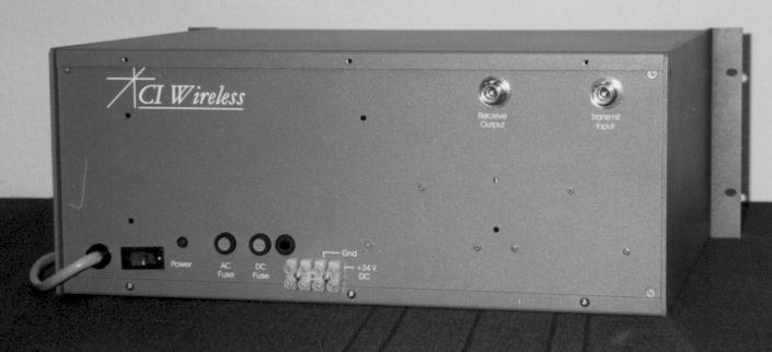
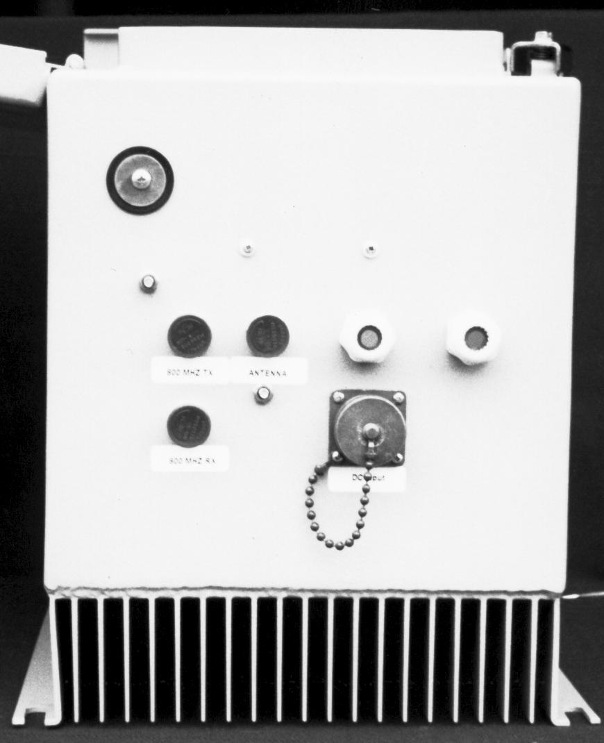
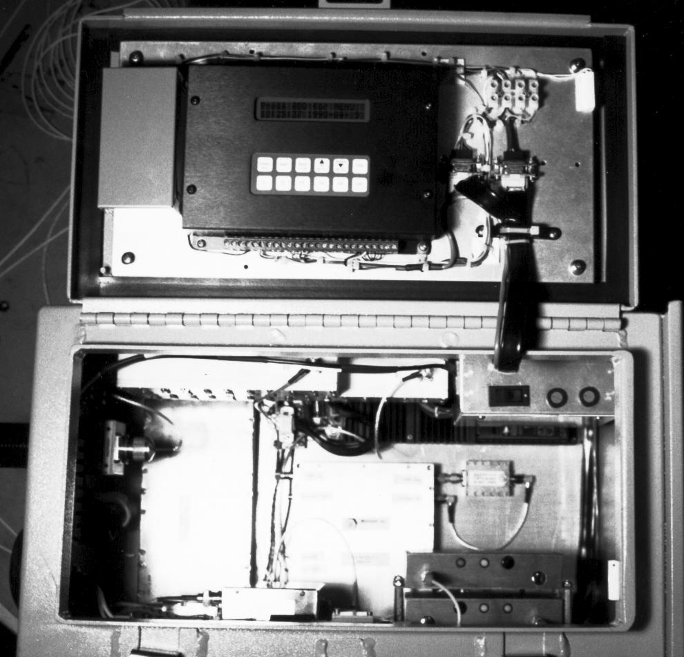
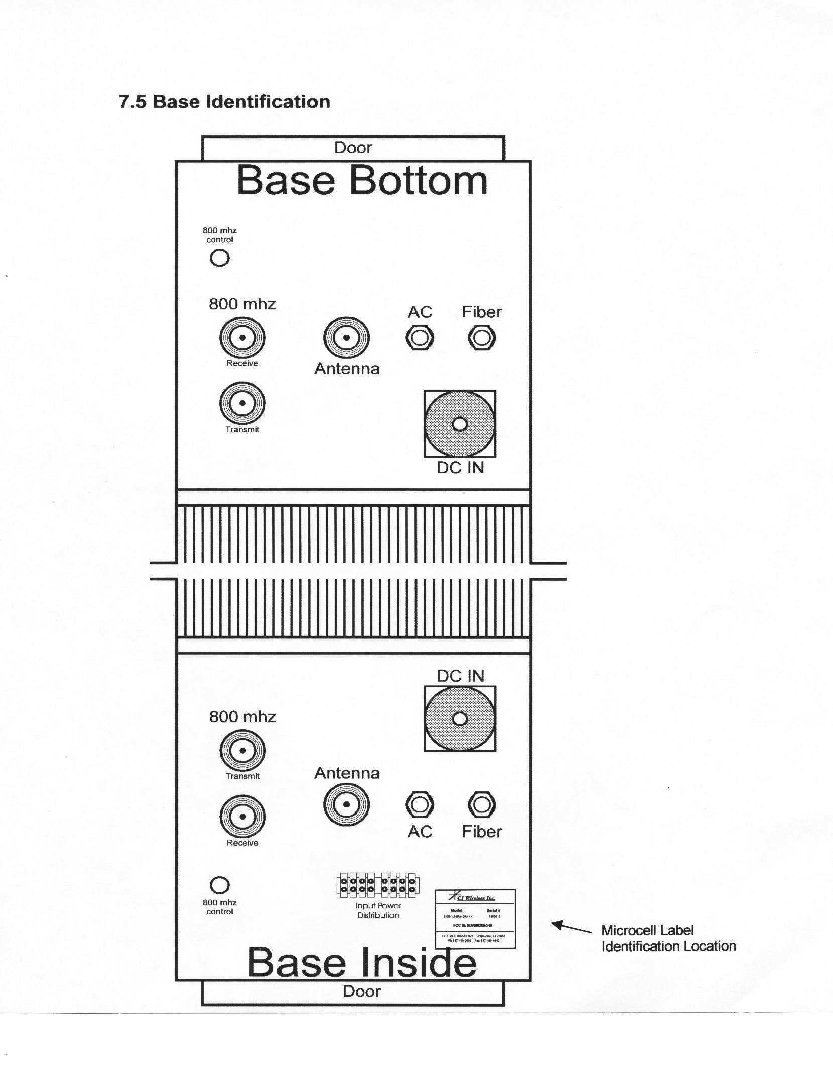
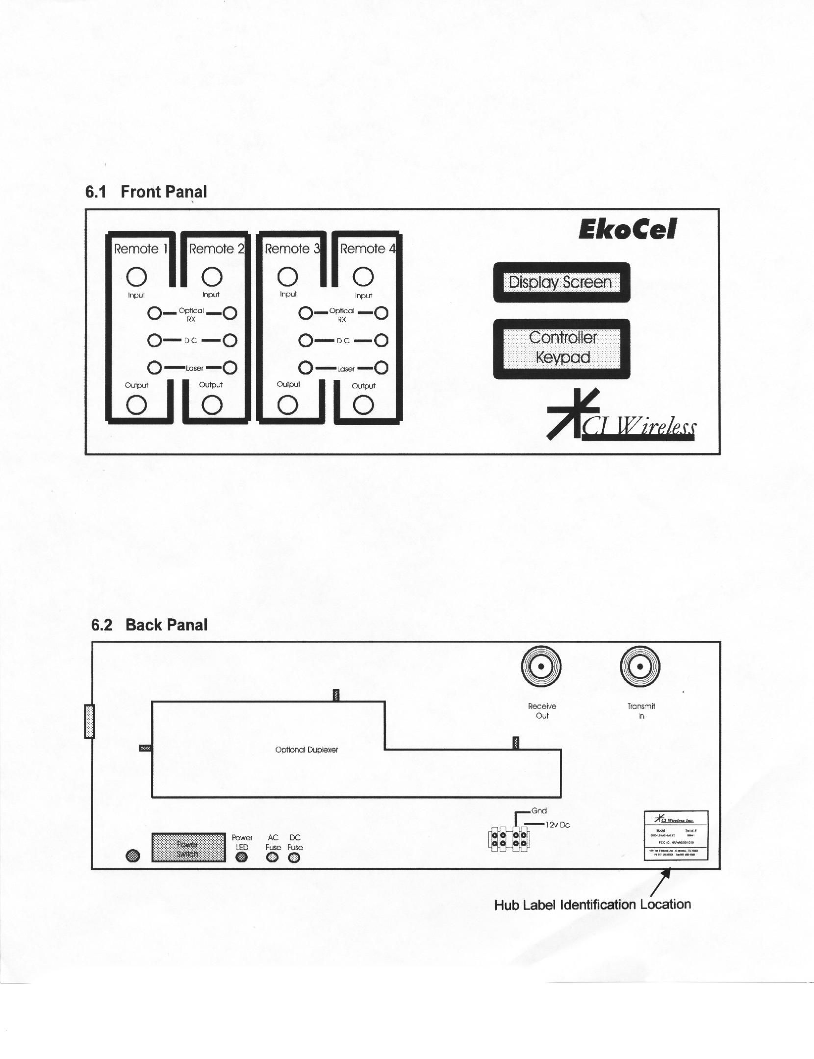
Exhibit A - Technical Report CI Wireless Inc. EKO-19 FCC ID: NUW002EKO19 Applicant Name and Address The CI Wireless Inc. EKO-19 PCS extender FCC ID: NUW002EKO19 covered under this application was designed, manufactured and assembled by CI Wireless, Inc. Their full name and mailing address is given below. CI WIRELESS, INC. 1211 Ira E. Woods Ave./Hwy. 26 Grapevine, Texas 76051 Model Name The model name for the system covered under this application is: EKO-19. The EUT is comprised of a Hub unit and an associated Microcell unit. The Hub/Microcell model numbers will be: For band A: EKO-1.9 MAX-XXXXXX /.EKO-1.9 HAX-XXXXXX. For band B: EKO-1.9 MBX-XXXXXX /.EKO-1.9 HAX-XXXXXX. For band D: EKO-1.9 MDX-XXXXXX /.EKO-1.9 HAX-XXXXXX. Th exact model number for each EKO-19 is based on installed options. The options, however, do not have an impact on certification of the equipment. The index for model number generation is shown below: Model Number Indentification Exhibit B - Expository Statement CI Wireless, Inc. EKO-19 Description of Equipment The CI Wireless Inc., EKO-19 PCS Extender/Enhancer is comprised of a Hub unit and a Microcell unit. Detailed descriptions of each unit are given below: Hub Unit The Hub unit provides the hardware interface to the base station and the fiber optic cables that will transport the RF signals to the Microcell Units. The Hub will support up to 4 Microcell Units by installing additional Fiber Optic Transceivers. Each of these Microcell Units will be individually alarmed and controlled. The optical path to each of the Microcell Units may be up to 20 kilometers in length. Microcell Unit The Microcell Unit provides all of the electronic hardware to interface to the fiber optic cable and the required amplifiers to process the up link and down link RF signals. The up link and down link signals are duplexed to a single radiating antenna via a coaxial cable. Access to alarms and controls for the hub and other Microcell Units is available via the control module. The product manual contains the following pertinent information Sections 4.1 through 5.11: Function of each active circuit device. Sections 9.5 through 9.6.1:Tune-up procedure, see Set up system instructions Appendix B:Model number nomenclature. The range of operating power values are as follows: CDMA1RF Carrier*2 watts 2 RF Carriers 1 watt/channel 3 RF Carriers .5 watts/channel GSM1 RF Carrier*2 watts 2 RF Carriers 1 watt/channel 3 RF Carriers .5 watts/channel NADC1 RF Carrier*2 watts 2 RF Carriers .5 watts/channel 4 RF Carriers250 mw/channel 8 RF Carriers100 mw/channel * Denotes maximum power ratings
Test Report
-FCC ID# NUW002EKO19 Professional Testing (EMI), Inc.1 Exhibit E - Measurement Report CI Wireless, Inc. EKO-19 FCC ID# NUW002EKO19 Professional Testing (EMI), Inc.2 Table of Contents Title Page .............................................................................................................................................................................. 1 Table of Contents ................................................................................................................................................................. 35 Certificate of Compliance .................................................................................................................................................... 36 1.0 Equipment Under Test (EUT) Description .................................................................................................................. 37 2.0 Power and Antenna Height Limits................................................................................................................................. 38 2.1 Test Procedure .............................................................................................................................................................. 38 2.2 Test Criteria................................................................................................................................................................... 38 2.3 Test Results ................................................................................................................................................................... 38 3.0 Frequency Stability ....................................................................................................................................................... 38 4.0 Modulation Characteristics ........................................................................................................................................... 38 5.0 Occupied Bandwidth..................................................................................................................................................... 38 6.0 Spurious Emissions at Antenna Terminals ................................................................................................................... 39 6.1 Test Procedure .............................................................................................................................................................. 39 6.2 Test Criteria................................................................................................................................................................... 39 6.3 Test Results ................................................................................................................................................................... 39 7.0 Field Strength of Spurious Emissions........................................................................................................................... 39 7.1 Test Procedure .............................................................................................................................................................. 39 7.2 Test Criteria................................................................................................................................................................... 39 7.3 Test Results ................................................................................................................................................................... 39 8.0 Signal Purity.................................................................................................................................................................. 40 8.1 Test Procedure .............................................................................................................................................................. 40 8.2 Test Criteria................................................................................................................................................................... 40 8.3 Test Results ................................................................................................................................................................... 40 9.0 List of Test Equipment.................................................................................................................................................. 40 Appendix A - Power Output Test Data................................................................................................................................ 42 Appendix B - Spurious Emissions at Antenna Terminals Test Data................................................................................... 43 Appendix C - Field Strength of Spurious Emissions Test Data .......................................................................................... 60 Appendix D - Signal Purity Test Data ................................................................................................................................. 72 Appendix E - Photographs ................................................................................................................................................... 80 FCC ID# NUW002EKO19 Professional Testing (EMI), Inc.3 Applicant:CI Wireless, Inc. Applicant’s Address:1211 Ira E. Woods Ave. Grapevine, TX 76051 Model:EKO-19 PCS extender Serial Number Hub198001 Serial Number Microcell:1980011 Project Number:98-385 Test Dates:April 8 through 9, 1998 I, Jeffrey A. Lenk, for Professional Testing (EMI), Inc., being familiar with the FCC rules and test procedures have reviewed the test setup, measurement data and this report. I believe them to be true and accurate. The CI Wireless Inc. EKO-19 PCS extender FCC ID: NUW002EKO was tested and found to be in compliance with FCC Parts 15 and 24 for Intentional Radiators. _________________________ Jeffrey A. Lenk President Certif…
Text truncated - open the document above for the full version.
Test Report
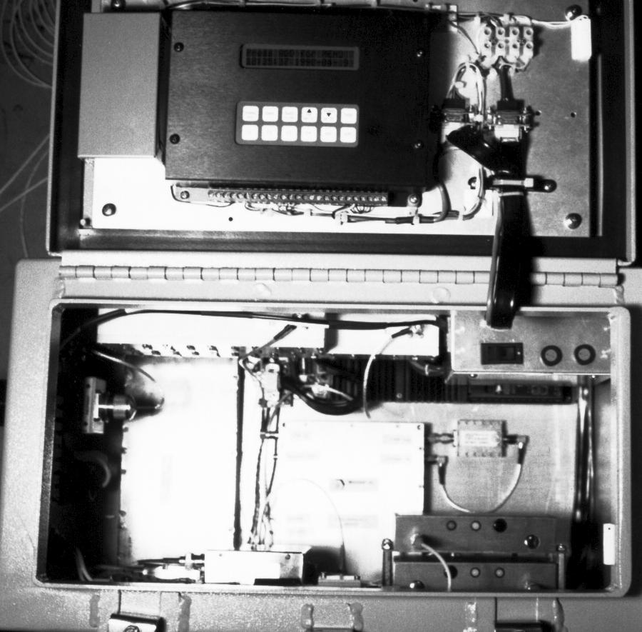
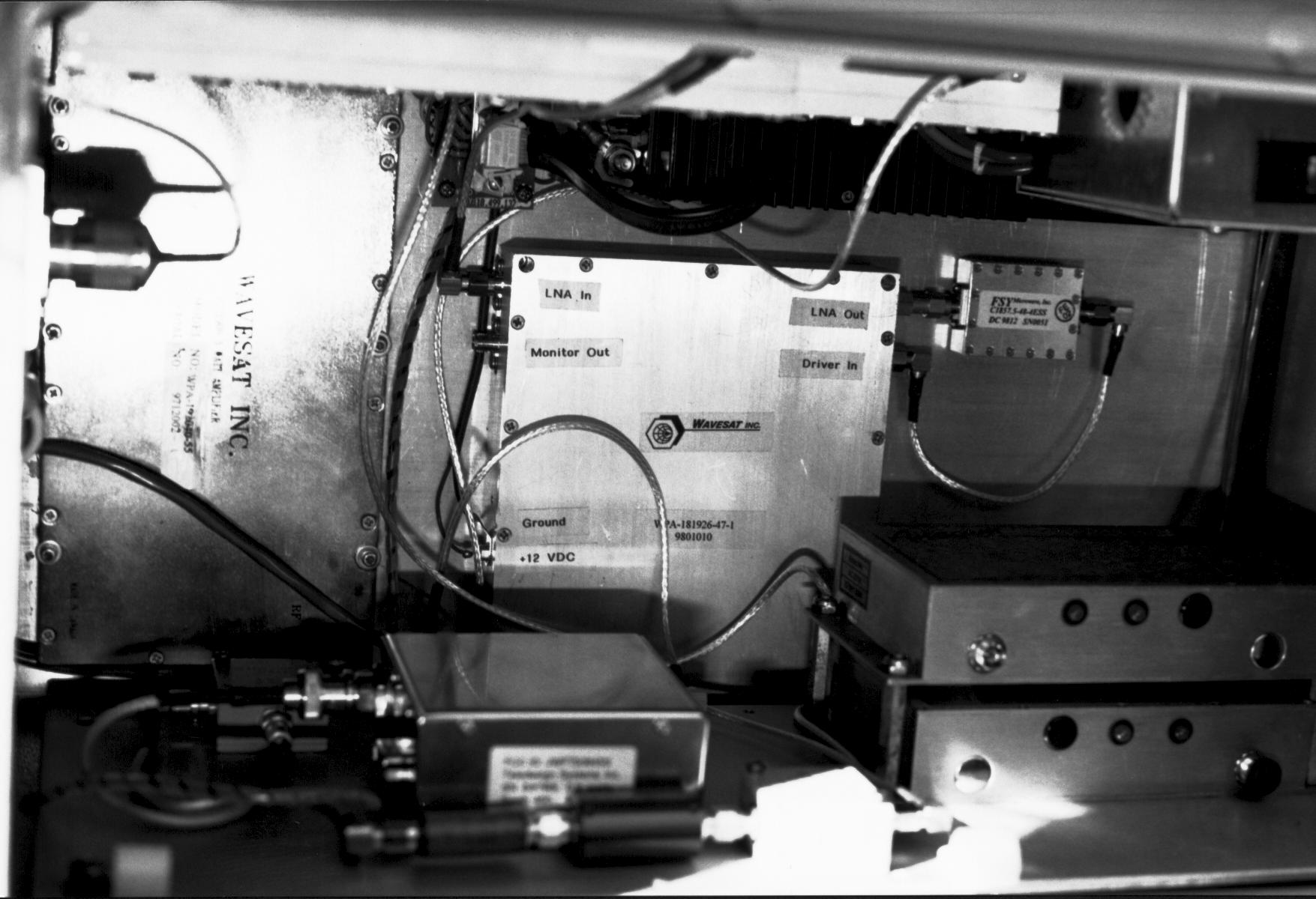
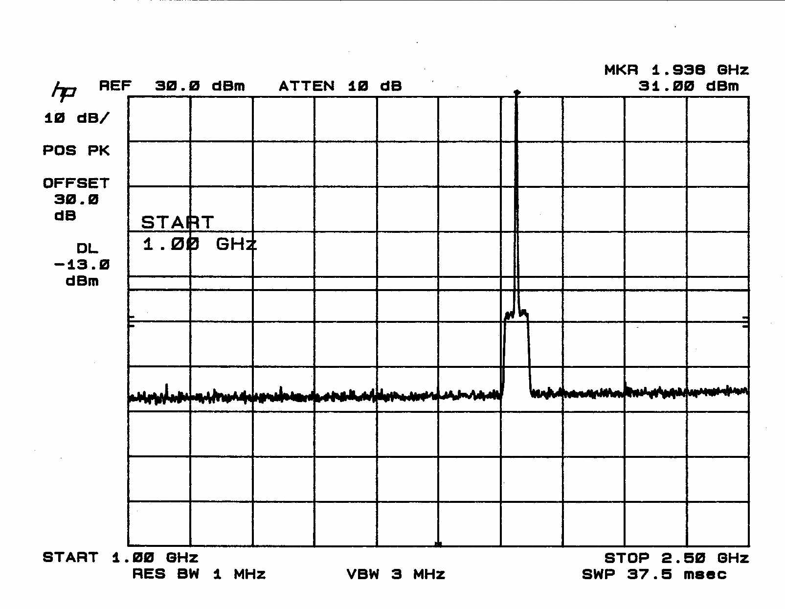
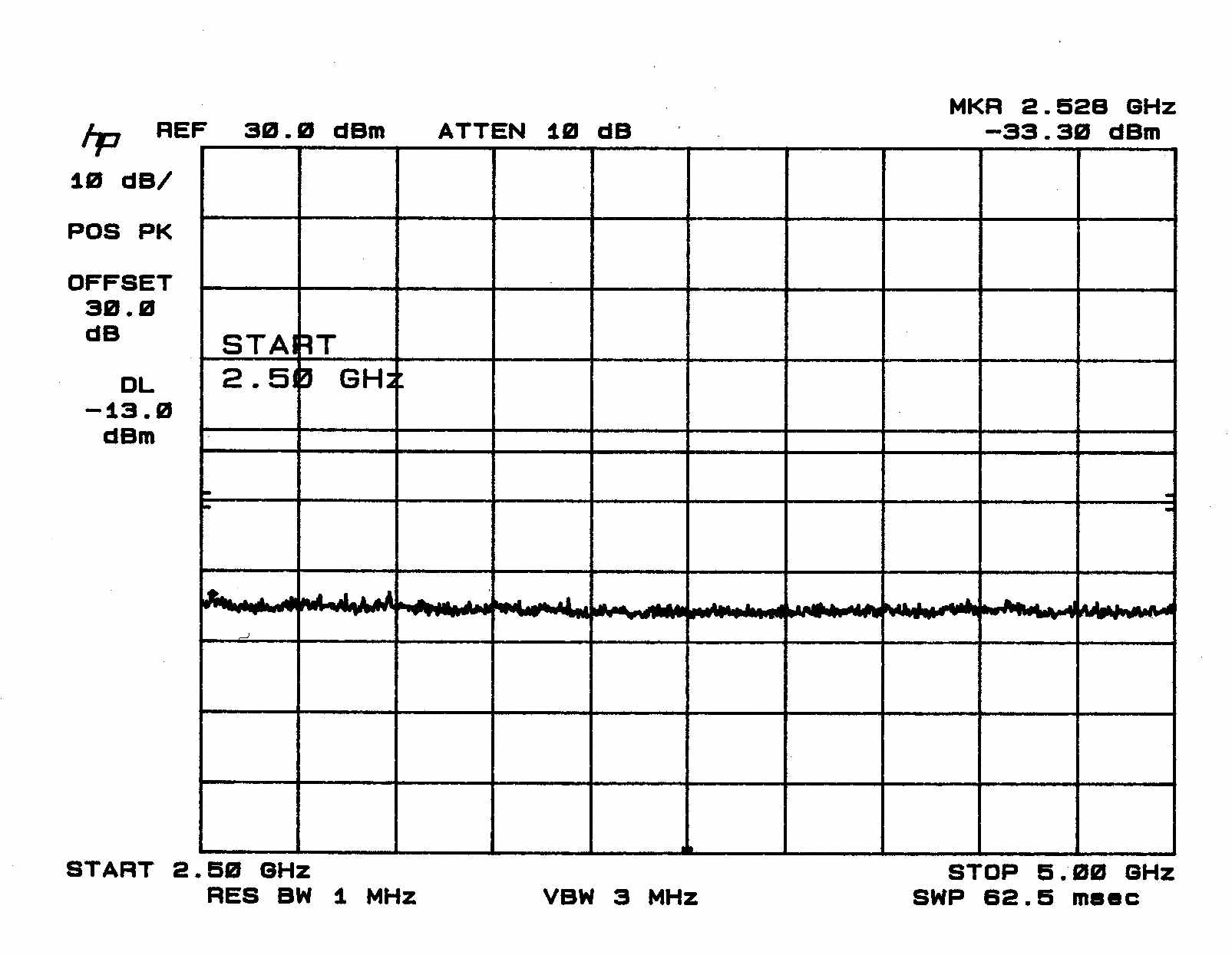
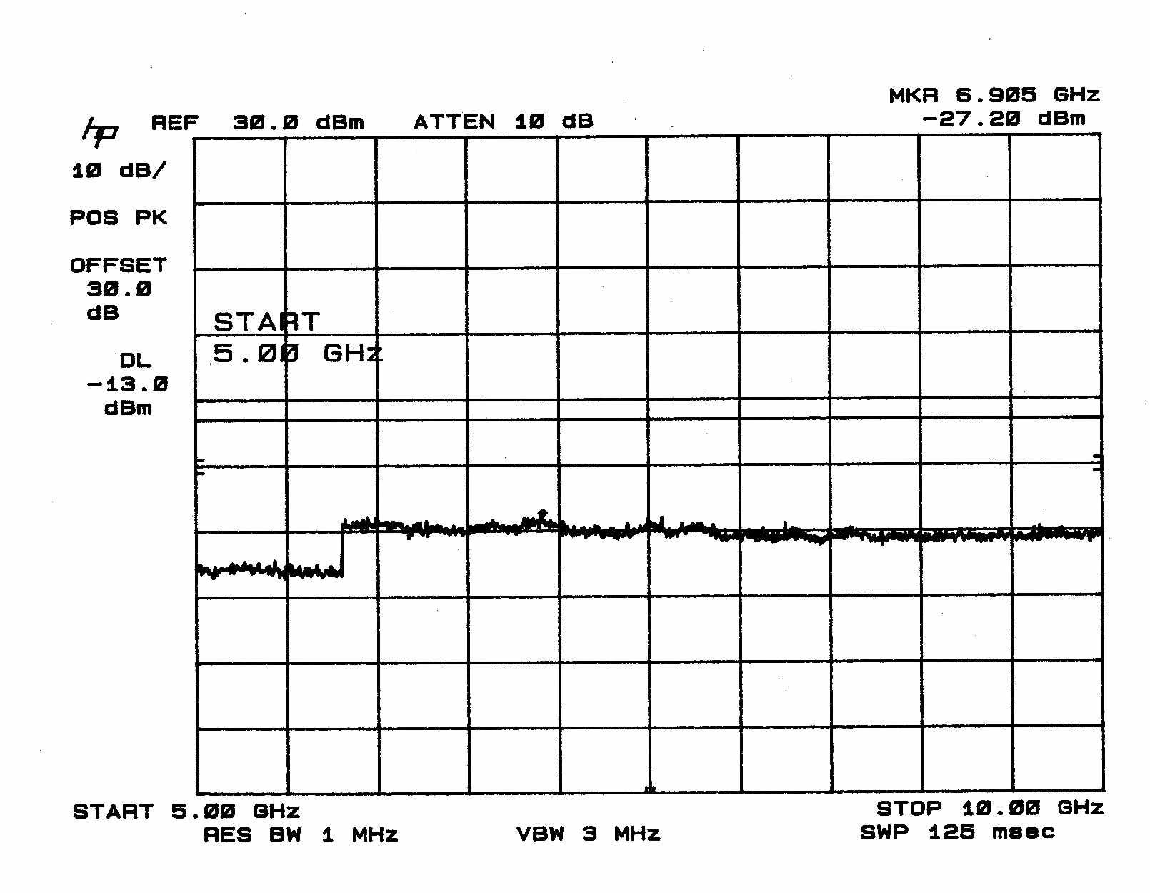
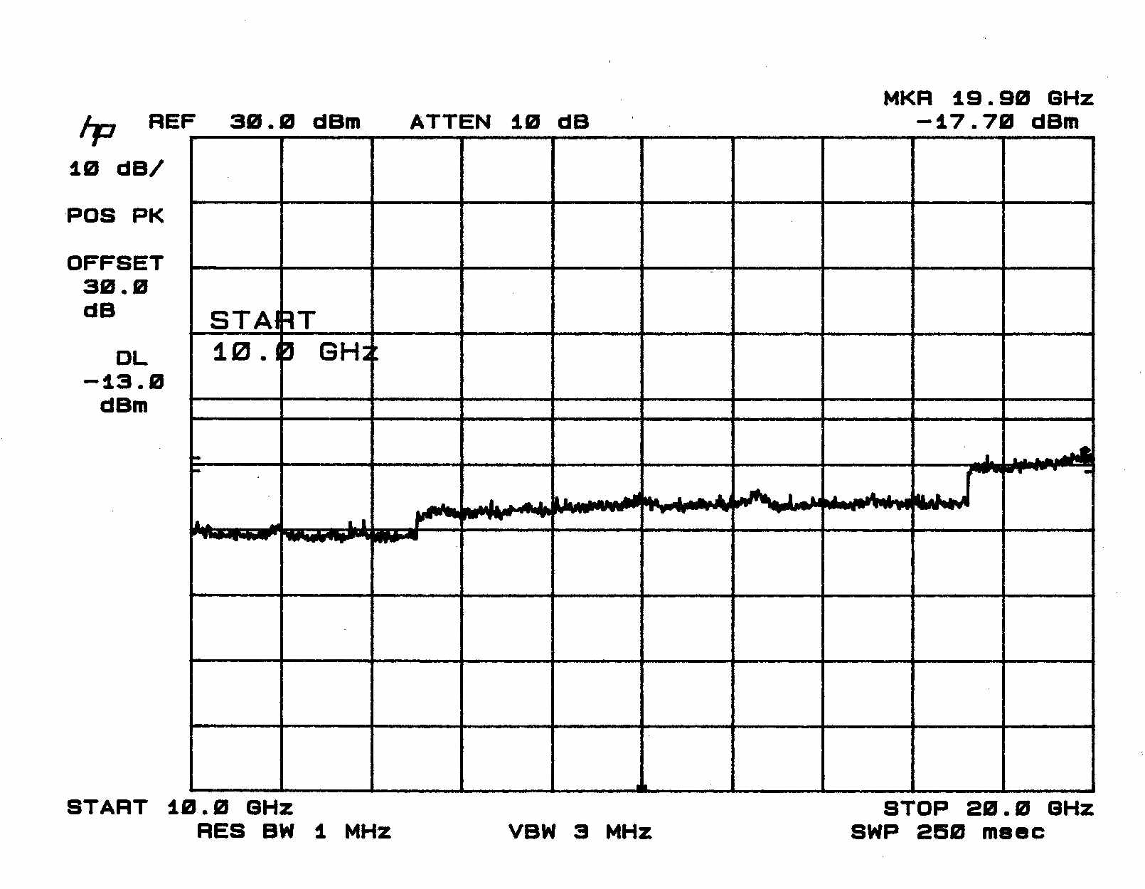
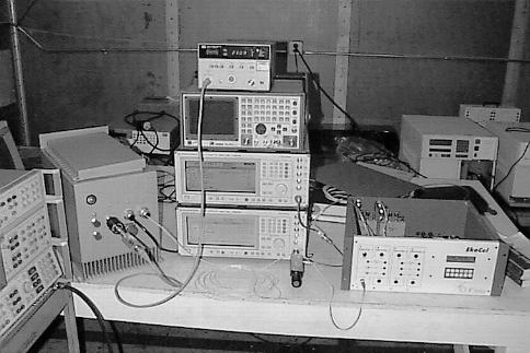
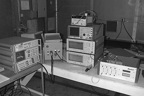
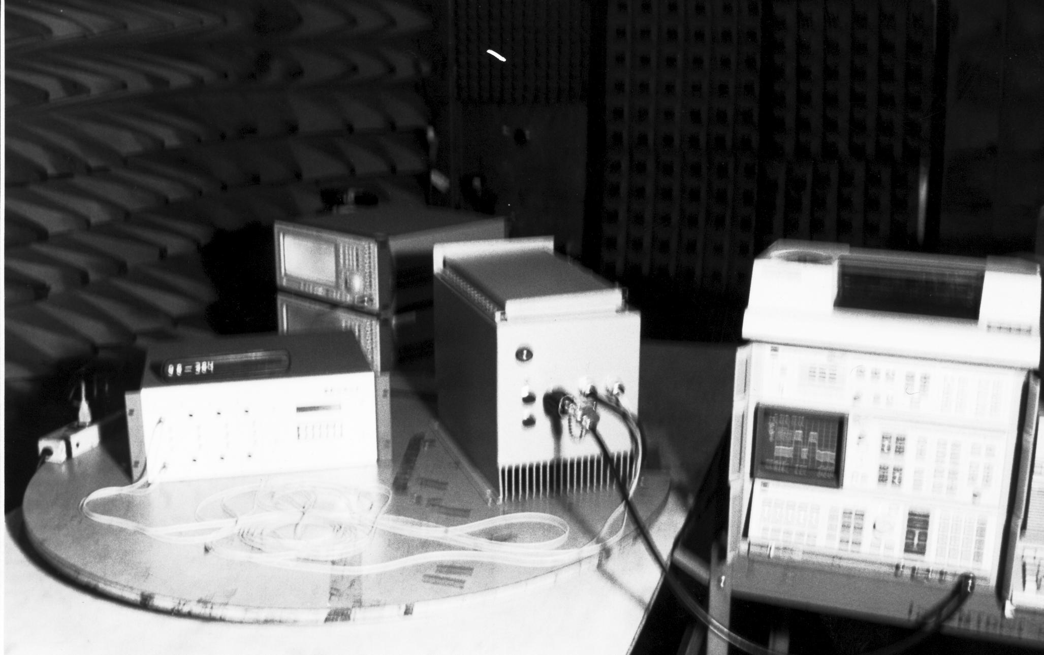
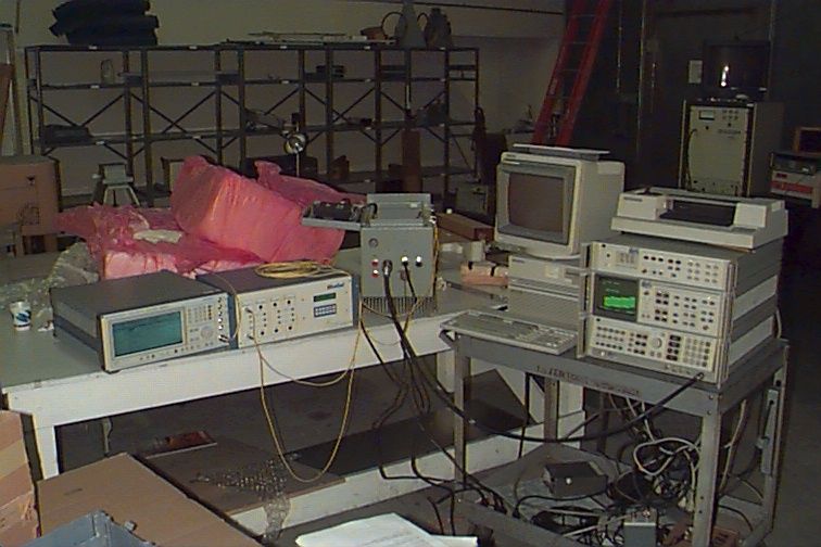
FCC ID# NUW002EKO19 1 1.0 Equipment Under Test (EUT) Description The CI Wireless, Inc., EKO-19 PCS Extender/Enhancer is a 1.9 GHz PCS service base station signal extender/enhancer. This system is comprised of a Hub and a Microcell unit. Hub Unit The Hub unit provides the hardware interface to the base station and the fiber optic cables that will transport the RF signals to the Microcell Units. The Hub will support up to 4 Microcell Units by installing additional Fiber Optic Transceivers. Each of these Microcell Units will be ndividually alarmed and controlled. The optical path to each of the Microcell Units may be up to 20 kilometers in length. Microcell Unit The Microcell Unit provides all of the electronic hardware to interface to the fiber optic cable and the required amplifiers to process the up link and down link RF signals. The up link and down link signals are duplexed to a single radiating antenna via a coaxial cable. Access to alarms and controls for the hub and other Microcell Units is available via the control module. The Hub unit and Microcell were tested together as a complete system (the EKO-19). The Microcell can be configured to operate in the A, B or D PCS bands. The EKO-19 was tested for compliance in the A, B, and D bands with CDMA, GSM, and NADC modulation. Measurements were performed to demonstrate compliance with FCC Rule Parts 2, and 24 subpart E, for Intentional Radiators. A separate verification report pursuant to Part 15, Subpart B has been prepared for the CI Wireless Inc. EKO-19 PCS extender as a Digital Device. Based on Part 15.101, testing and generation of a report for the receiver portion of the EKO-19 is not required because it operates above 960 MHz. The unit is subject to the provisions of Part 15.5. Specific test requirements include the following: 47 CFR 2.985 & 47 CFR 24.232Power and antenna height limits 47 CFR 2.995 & 47 CFR 24.235Frequency stability 47 CFR 2.987Modulation characteristics 47 CFR 2.989Occupied bandwidth 47 CFR 2.991 & 47 CFR 24.238Spurious emissions at antenna terminals 47 CFR 2.993 & 47 CFR 24.238Field strength of spurious emissions FCC ID# NUW002EKO19 2 47 CFR 15.107 & 47 CFR 15.109Radiated and Conducted Emissions FCC ID# NUW002EKO19 3 2.0 47 CFR 24.232 Power And Antenna Height Limits 47 CFR 24.232 provides limits for antenna height, peak equivalent isotropically radiated power and power measured at the output terminals for PCS base stations. Antenna height and radiated power limits only apply as the system is installed. The unit as manufactured is required to meet the limit for power at the output terminals. 2.1Test Procedure The EKO-19 was set up as per the tune-up procedure described in section 9.5.3 of the product manual. The signal generator was setup to output CW signal. The signal was fed into the EKO-19 Hub unit. The power was measured at the output terminal of the EKO- 19 microcell unit. The EKO-19 extender was operated with a 10dB attenuator connected to the antenna port then connected to an HP-436A power meter. 2.2Test Criteria The power output measured at the antenna terminal shall not exceed 100 Watts. 2.3Test Results The output power measured was below the limit. Power output was 32.3 dBm or 2 Watts. The test data appears in appendix A. Test set-up photographs appear in appendix E. 3.047 CFR 2.995 & 47 CFR 24.235 Frequency Stability Frequency stability requirements are not applicable to the EKO-19 because there are no frequency altering stages in this device. 4.047 CFR 2.987 Modulation Characteristics Modulation characteristics requirements are not applicable to the EKO-19 because the system simply receives, distributes, and rebroadcasts already modulated signals. Signal in vs. signal out tests were done to demonstrate signal purity through the EKO-19. See measurement section 8. 5.047 CFR 2.989 Occupied Bandwidth Occupied bandwidth requirements are not applicable to the EKO-19 because the system simply receives, distributes, and rebroadcasts alrea`dy modulated signals. Signal in vs. signal out tests were done to demonstrate signal purity through the EKO-19. See measurement section 8. FCC ID# NUW002EKO19 4 6.0 47 CFR 2.991 & 47 CFR 24.238 Spurious Emissions At Antenna Terminals The radio frequency power generated within the equipment and appearing on a spurious frequency shall be measured at the output terminals. 6.1 Test Procedure The EKO-19 extender was operated with 30dB attenuators connected to the antenna port then connected to an HP-8566B spectrum analyzer. Two tone CDMA, GSM, and NADC modulation was employed at frequencies closest to the upper and lower edges of bands A, B, and D. 6.2 Test Criteria Section 24.238 states that on any frequency outside a frequency block, the power of any emission shall be attenuated below the transmitter power by at least 43 + 10 log(power) dB. The limit, at the operating power of the EKO-19 extender is -16 dBm. 6.3Test Results Spurious emissions outside of the allowed frequency block were below the -16 dBm limit. The test data appears in appendix B. Test set-up photographs appear in appendix E. 7.047 CFR 2.993 & 47 CFR 24.238 Field Strength Of Spurious Emissions The EKO-19 was measured for case radiation as operated with a dummy load at the antenna terminals. 7.1 Test Procedure The EKO-19 extender was operated with 30dB attenuators connected to the antenna port. The EUT was placed on a non-conductive table 0.8 meter high in a 20’ x 26’ x 10’ semi- anechoic shielded room. The receiving antenna was placed 1 meter from the EUT. The antenna height was 0.8 meter. A HP-8566B spectrum analyzer was used to measure the emissions. The EKO-19 was operated at rated power in CW mode. 7.2Test Criteria Information submitted shall include the relative radiated power of each spurious emission with reference to the rated power output of the transmitter, assuming all emissions are radiated from a halfwave dipole antenna. Limits were set assuming a -13 dBm transmitter radiating through a half wave d…
Text truncated - open the document above for the full version.
Test Report
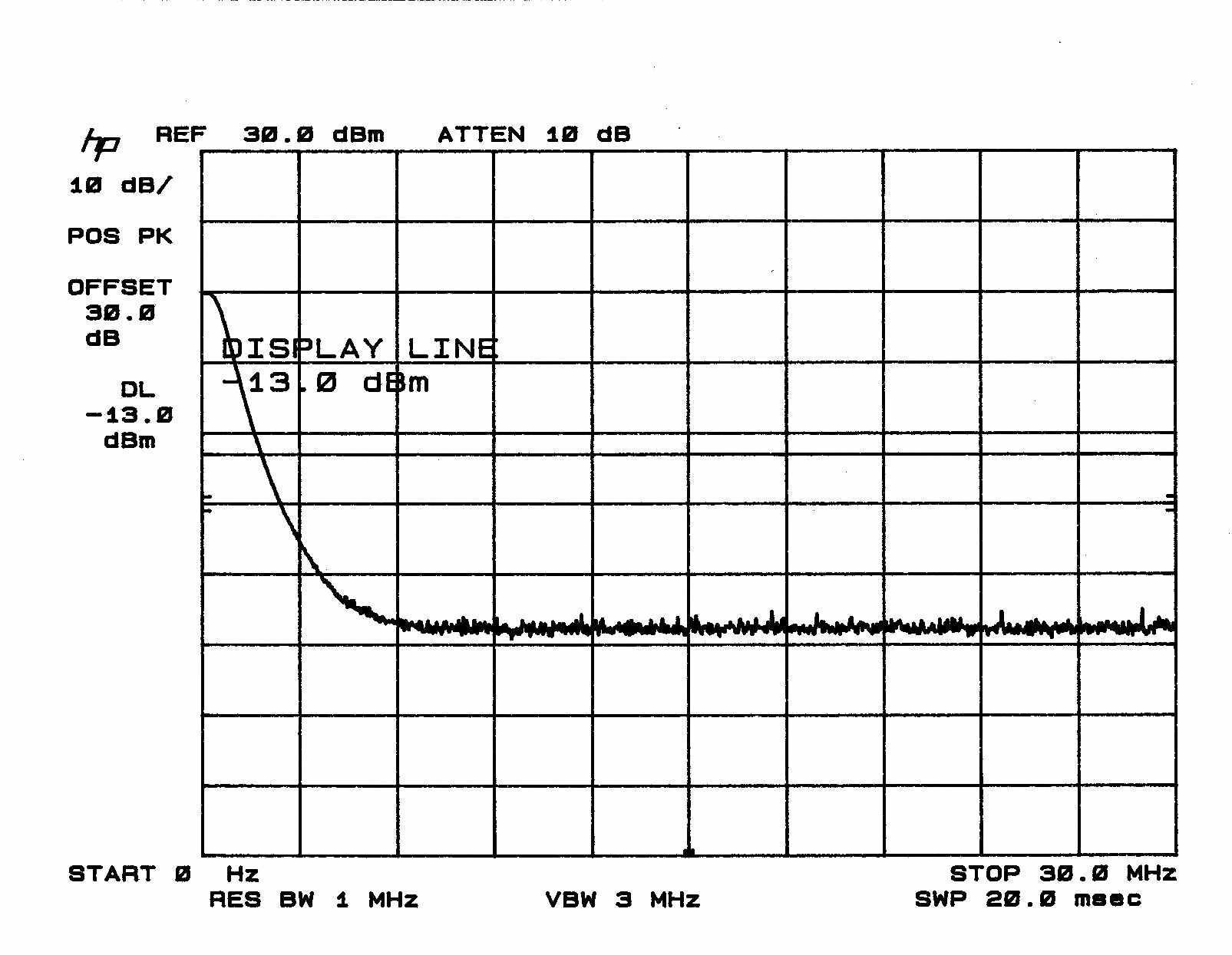
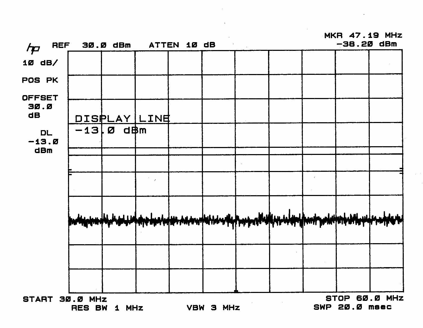
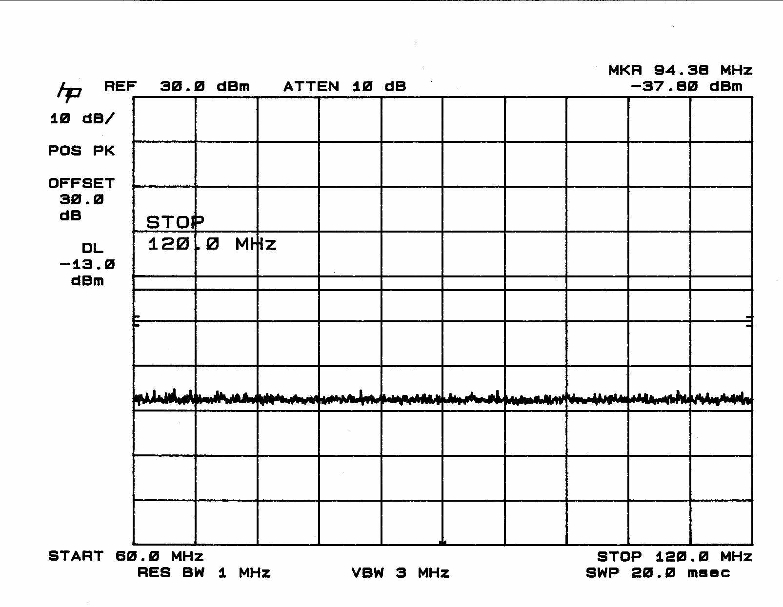
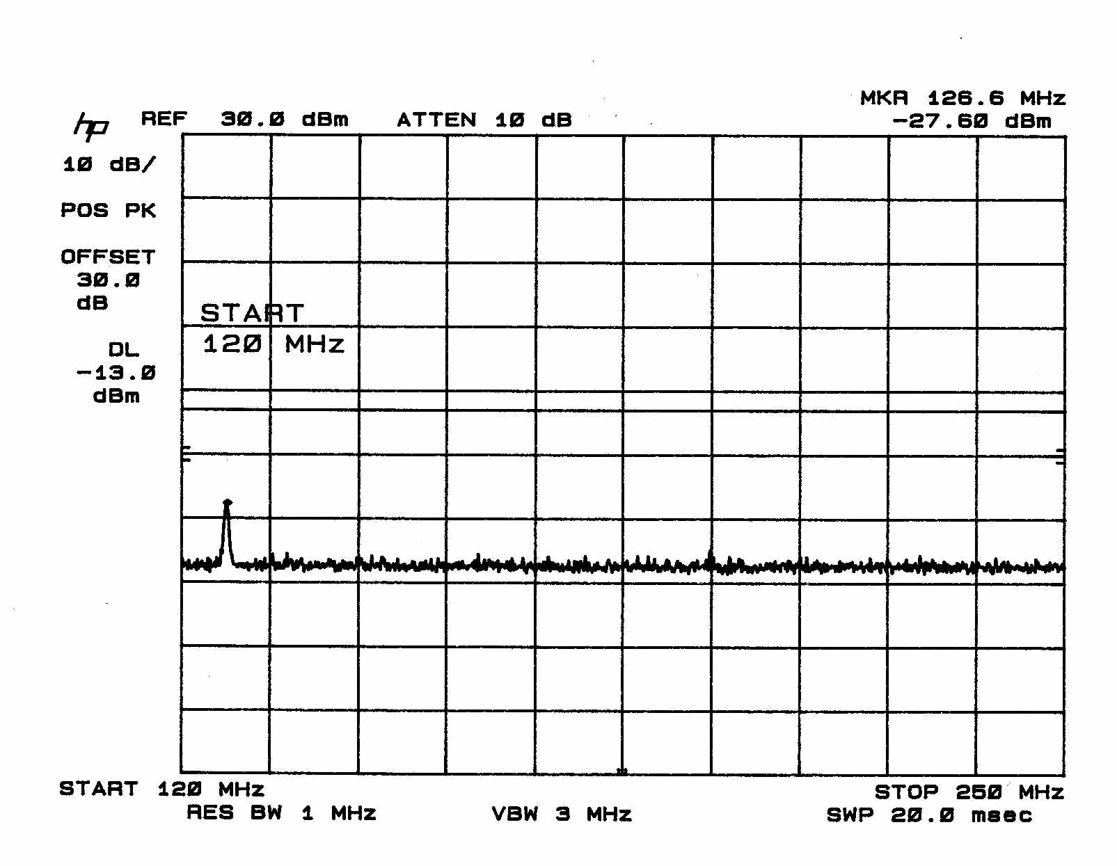
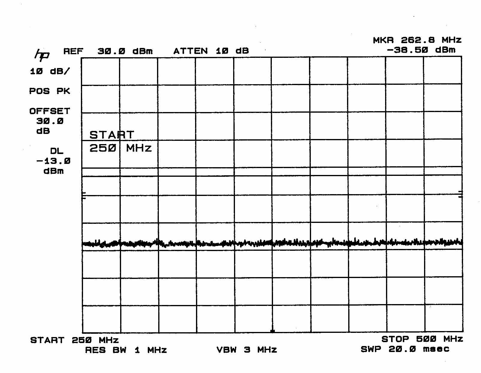
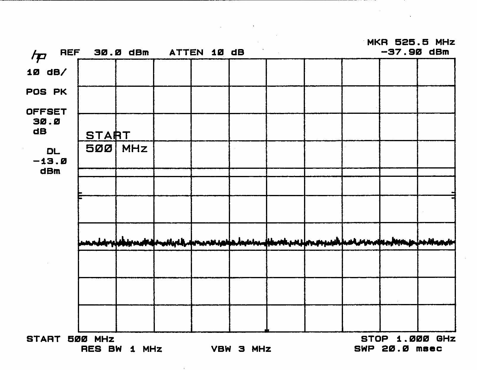
1.0 Spurious Emissions At Antenna Terminals The radio frequency power generated within the equipment and appearing on a spurious frequency shall be measured at the output terminals. 1.1 Test Procedure The EKO-19 extender was operated with 30dB attenuators connected to the antenna port then connected to an HP-8566B spectrum analyzer. A CW signal was input to the EKO- 19. 1.2 Test Criteria Section 24.238 states that on any frequency outside a frequency block, the power of any emission shall be attenuated below the transmitter power by at least 43 + 10 log(power) dB. The limit, at the operating power of the EKO-19 extender is -13 dBm. 1.3Test Results Spurious emissions outside of the allowed frequency block were below the -13 dBm limit.
Contact Information
Applicant
Richard E Kent(Assistant General Counsel)
Technical Contact
Professional TestingJeffery A Lenk
[email protected]512 244 3371
1303 W. Industrial Blvd. · Round Rock, Texas · United States
Non-Technical Contact
Professional TestingJeffery A Lenk
[email protected]512 244 3371
Technical Specifications
| # | Rule Parts | Frequency Range | Power Output | Emission | Tolerance |
|---|---|---|---|---|---|
| 3 | 24E | 1.93 GHz - 1.97 GHz | 2 W | DXW | Amp |
Other Applications from EMS Technologies Inc
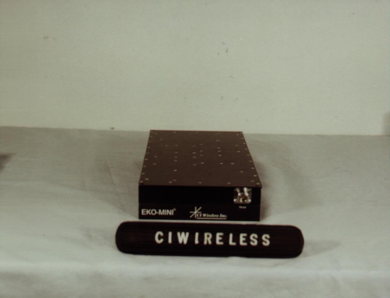
NUW0A1MINI19
Feb 13, 20001900 MHz PCS Repeater
Equipment Class
AMP - Amplifier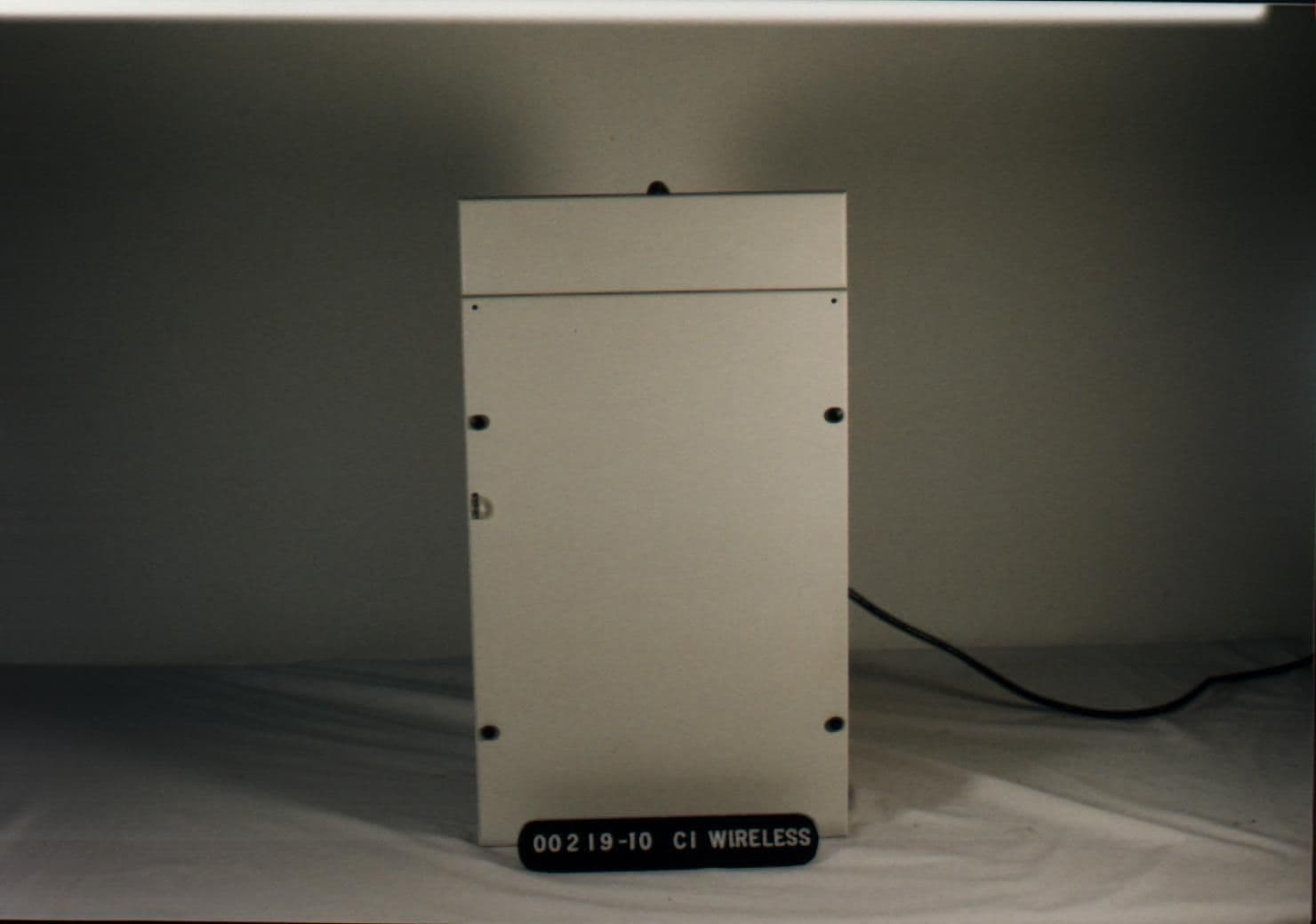
NUW008CMIR8
Feb 06, 2000Cellular Repeater
Equipment Class
AMP - Amplifier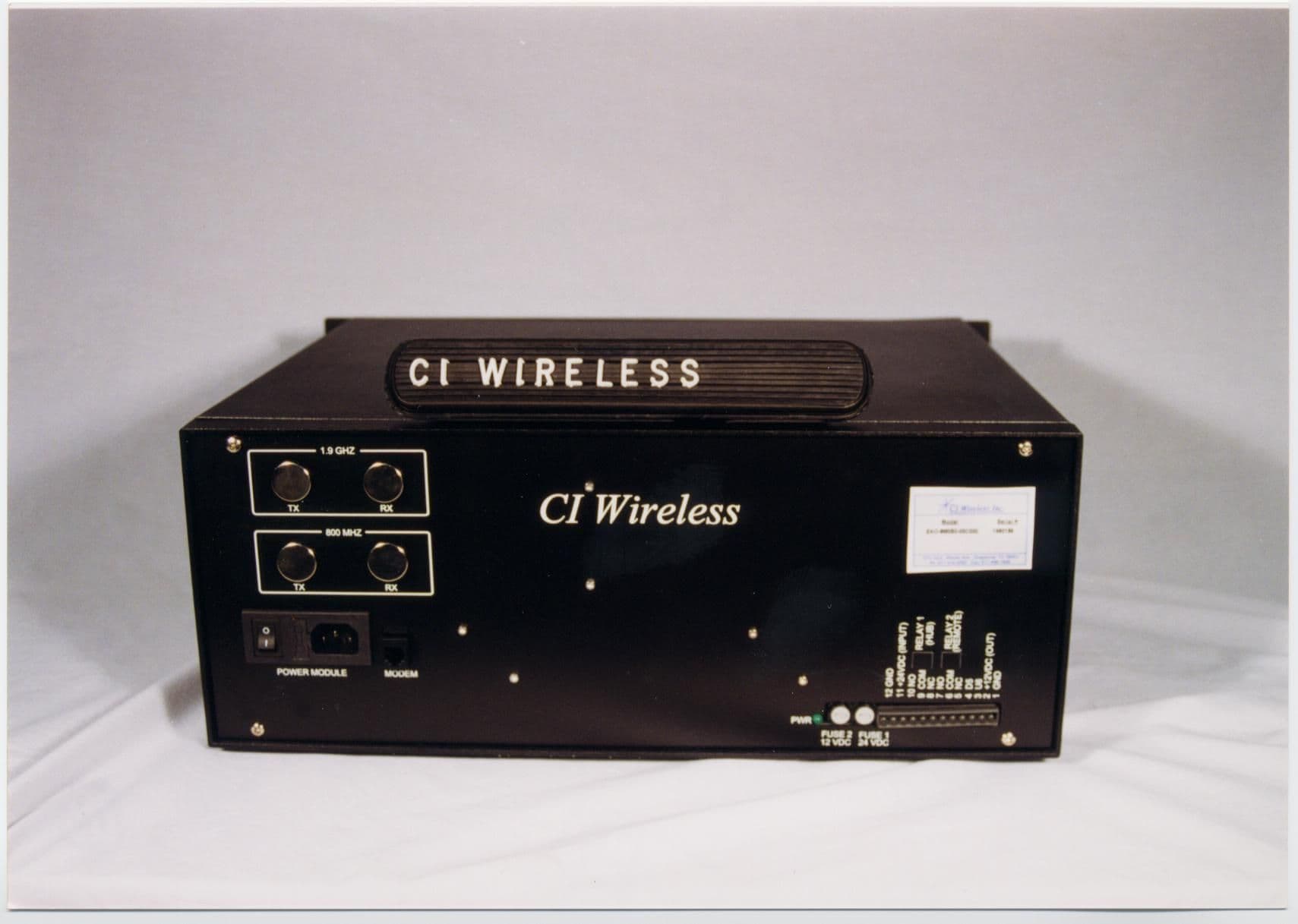
NUW050CEKO8
Dec 09, 1999Cellular Repeater
Equipment Class
AMP - Amplifier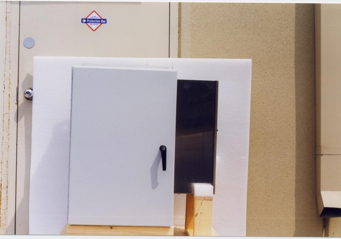
NUW050SEKO8
Oct 04, 1999ESMR Antenna Extender
Equipment Class
AMP - Amplifier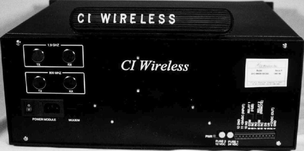
NUW004SEKO8
Apr 25, 1999800 MHz ESMR Band EkoCell Repeater
Equipment Class
AMP - Amplifier