NUW050CEKO8Cellular Repeater
EMS Technologies Inc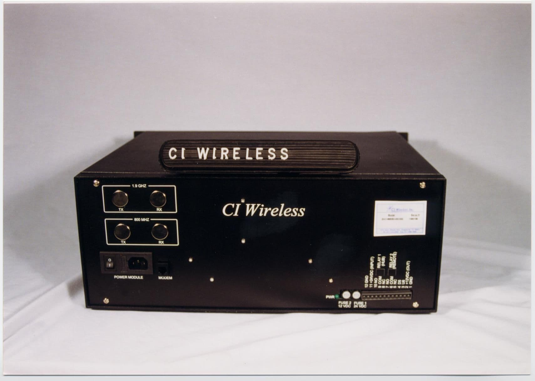
Click to zoom
Application Details
- Equipment Class
- AMP - Amplifier
- Date of Grant
- Dec 09, 1999
- Application Purpose
- Original Equipment
- Date of Application
- Jun 27, 1999
- Equipment Note
- Cellular Repeater
- Frequency Range
- 869.00000000 - 894.00000000
- Company
- EMS Technologies Inc
- Country
- United States
Documents & Files
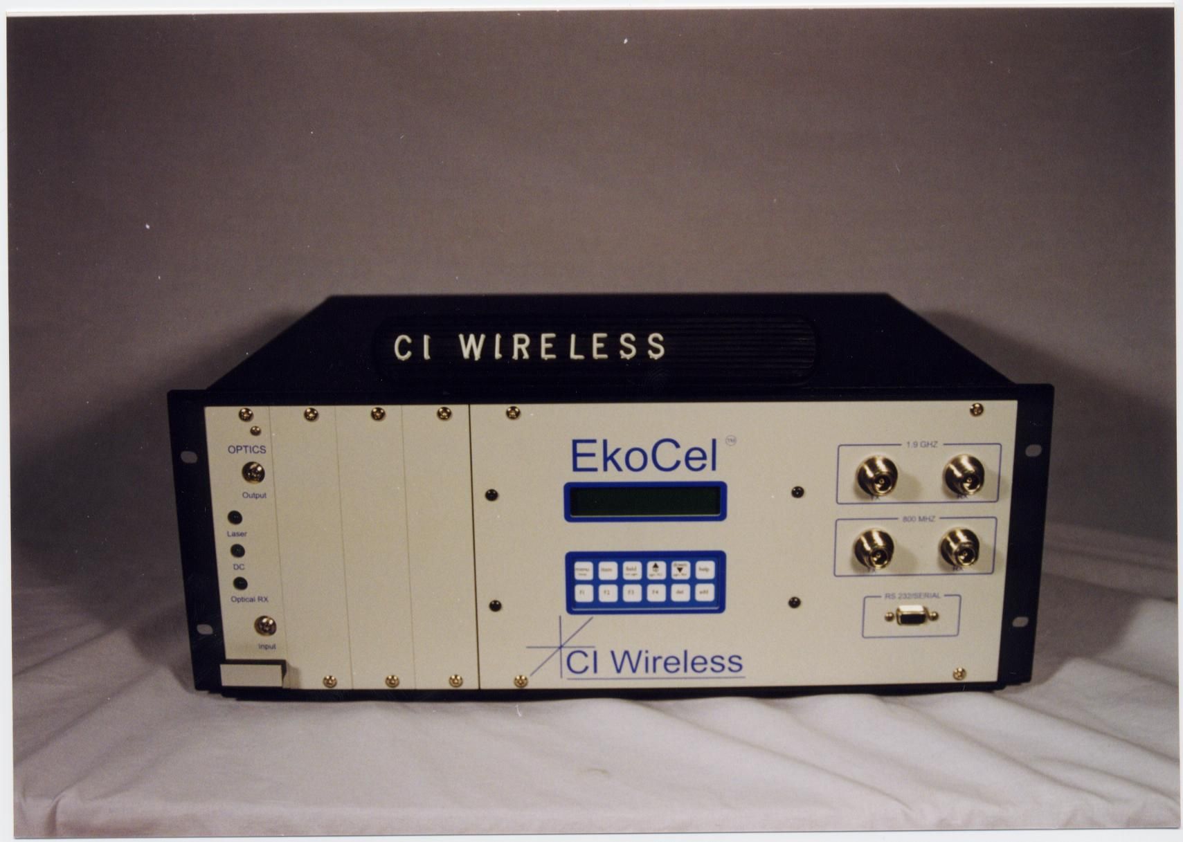
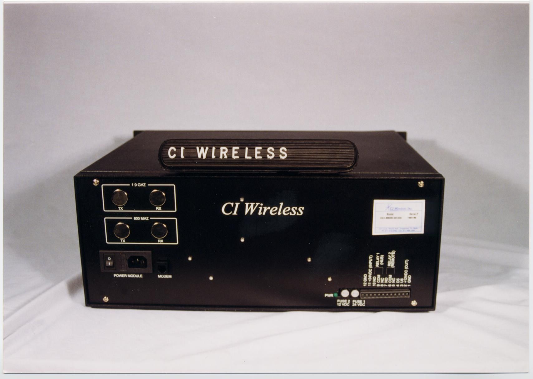
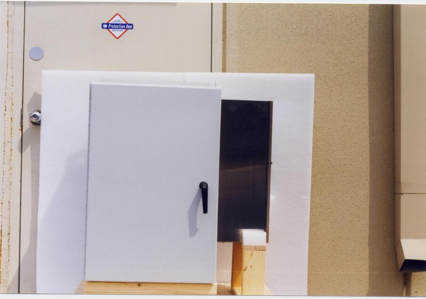
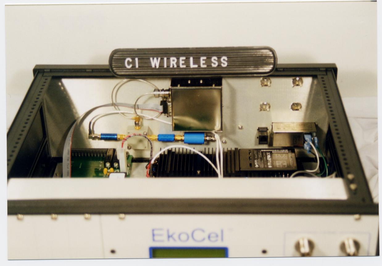
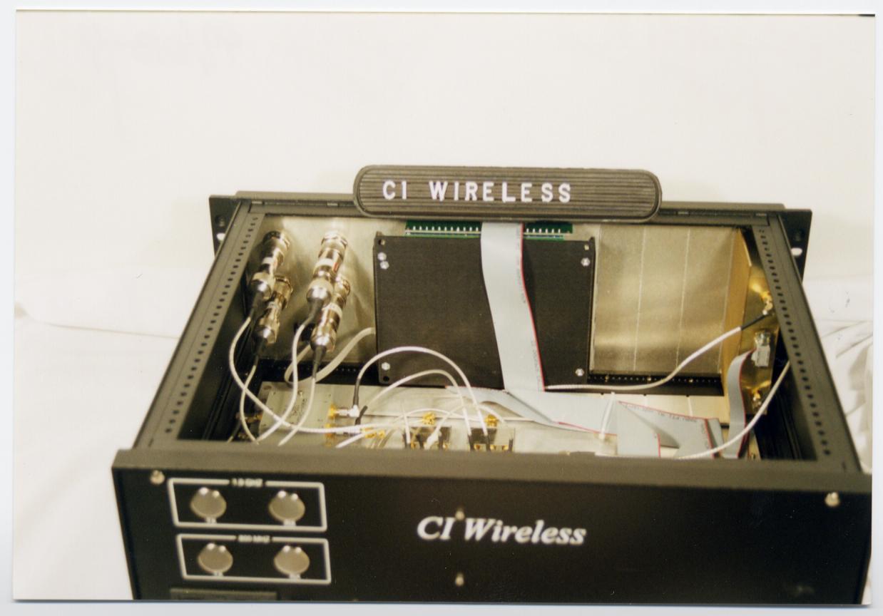
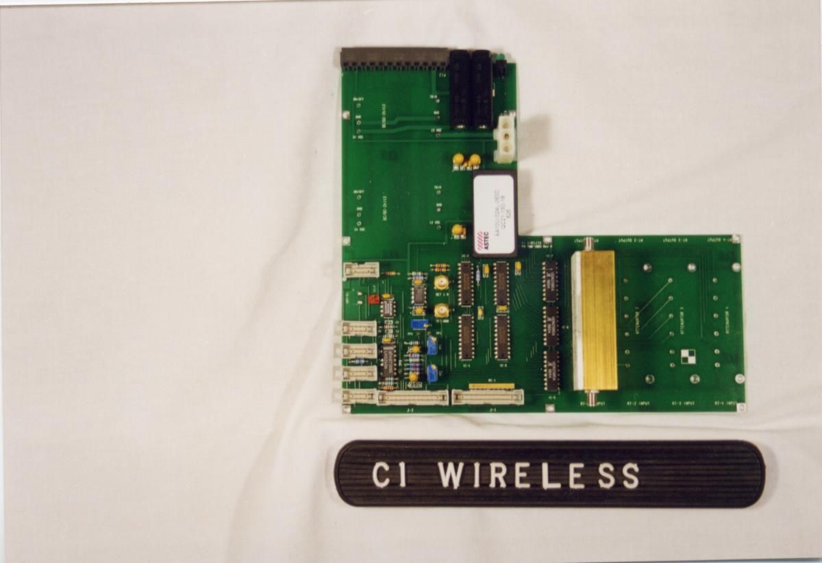
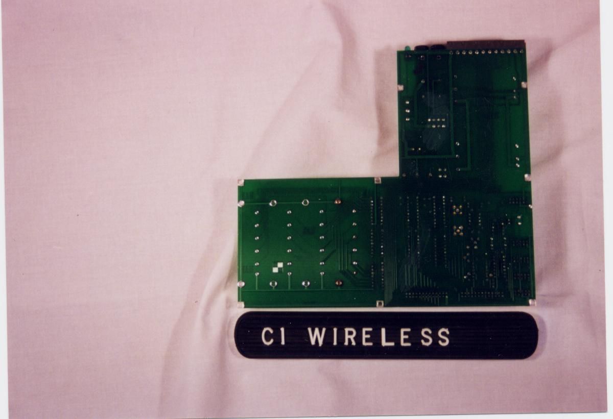
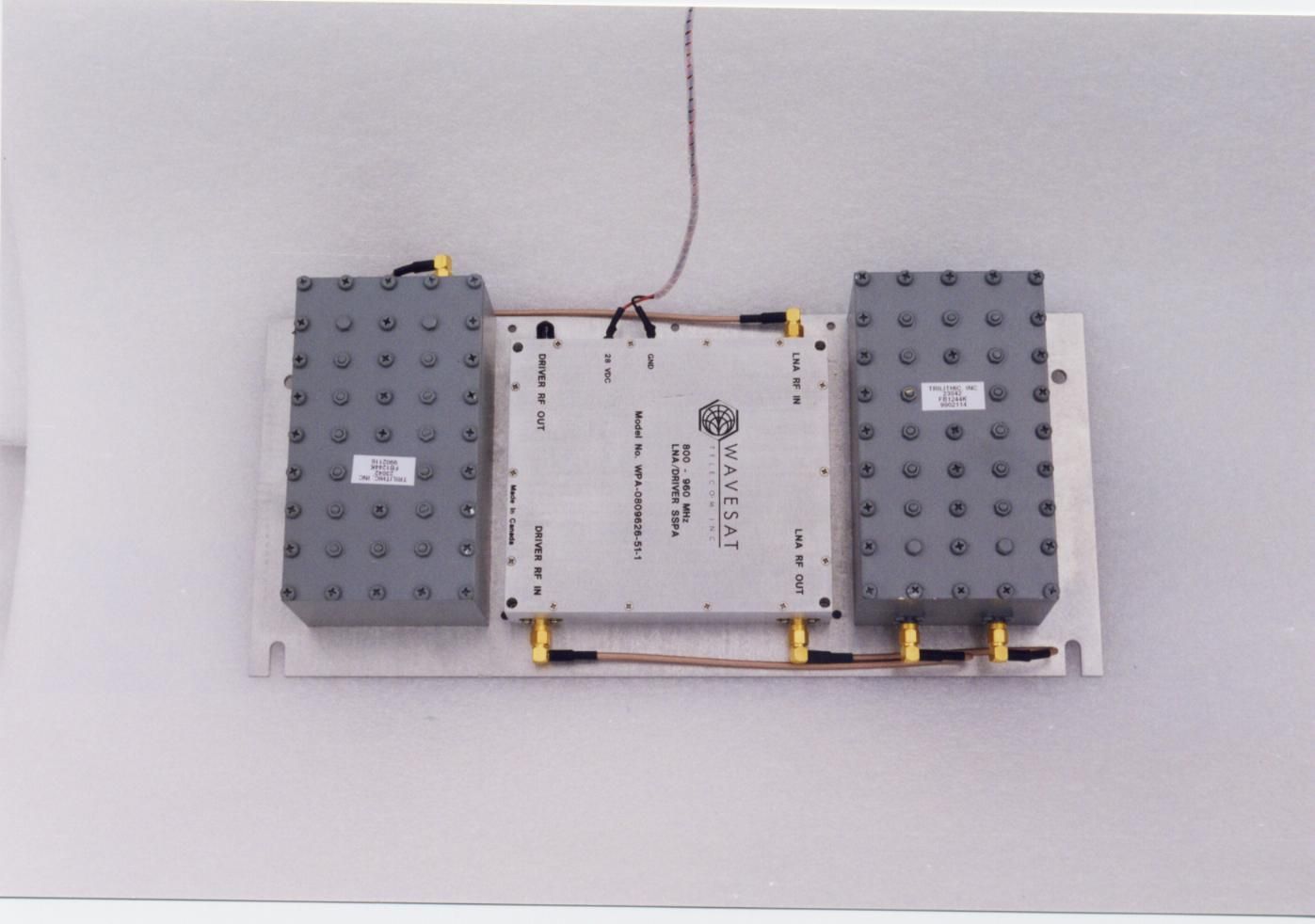
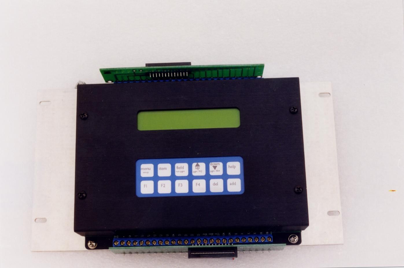
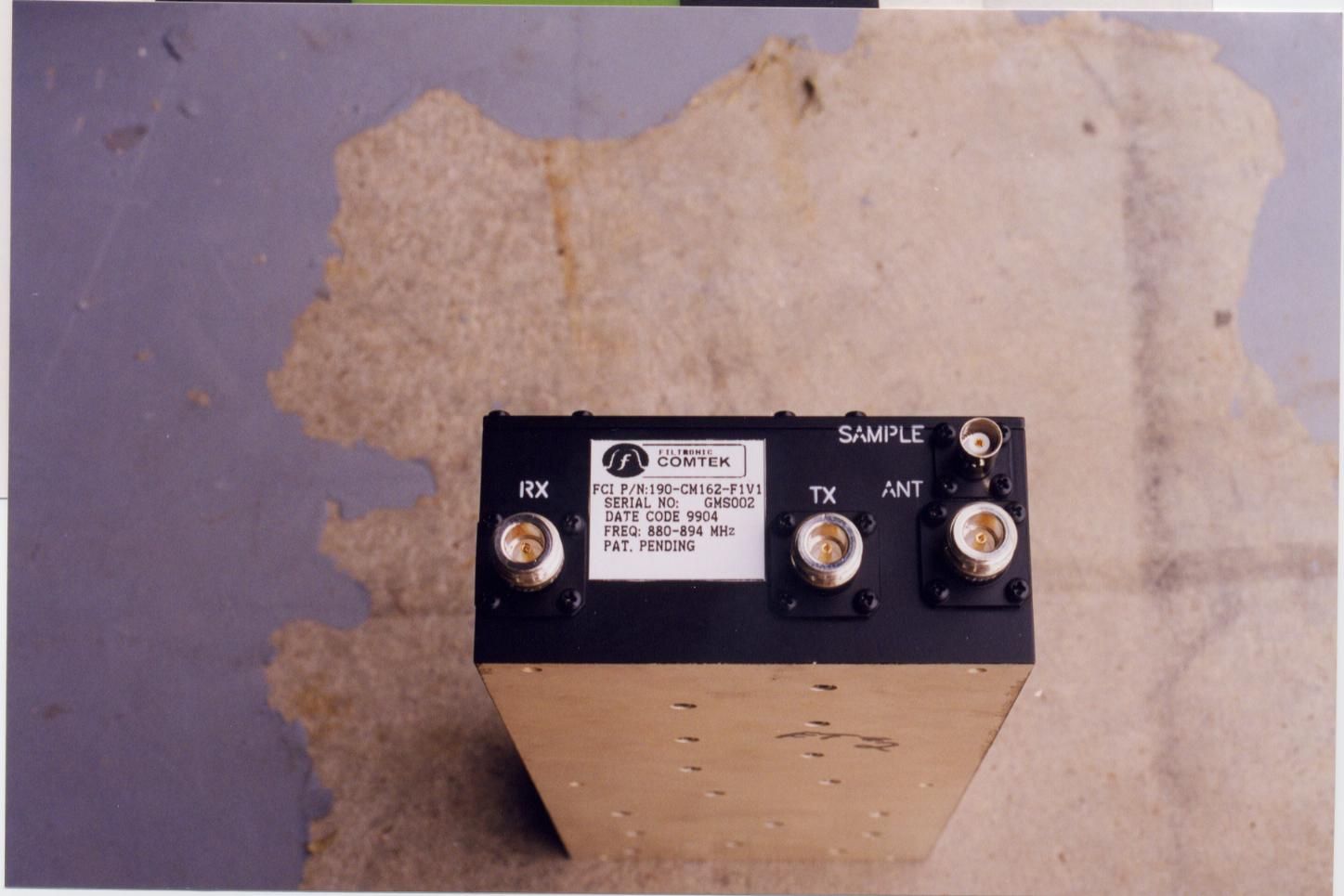
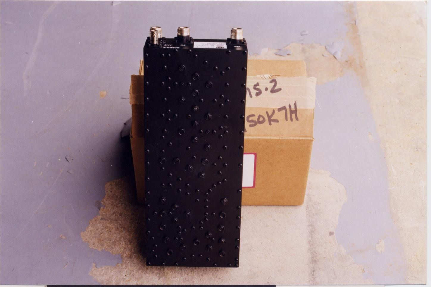
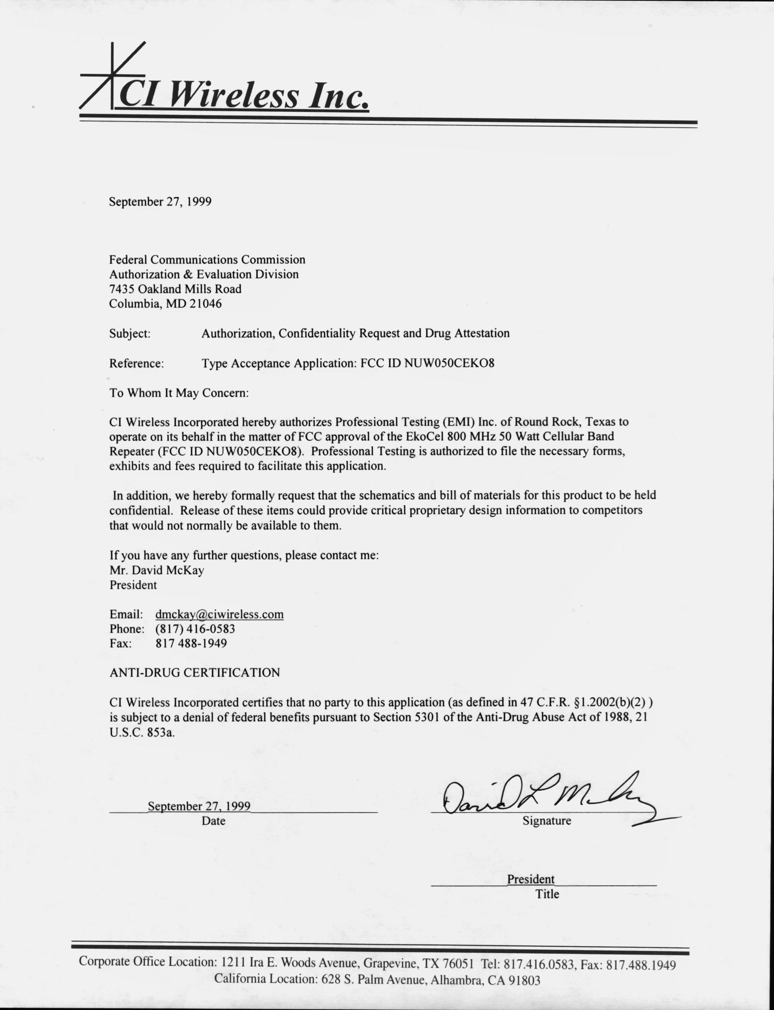
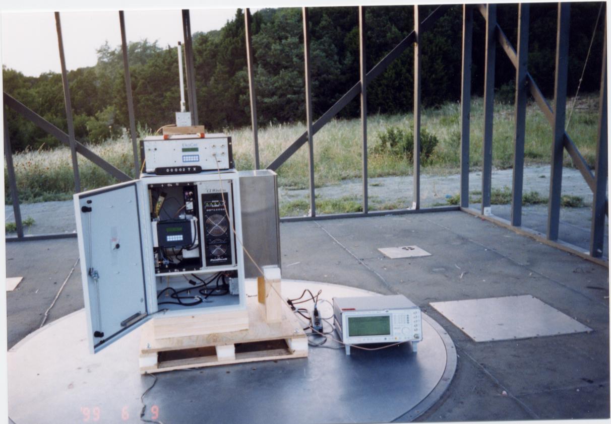
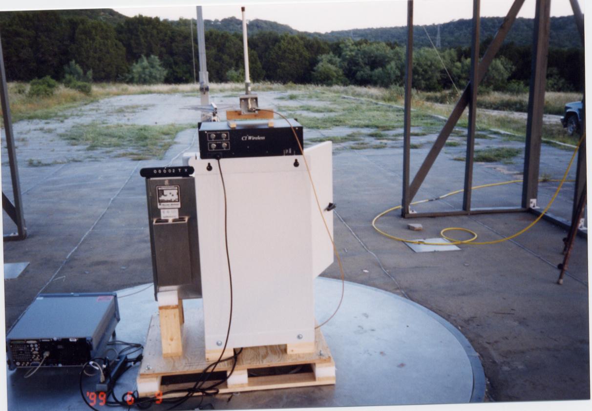
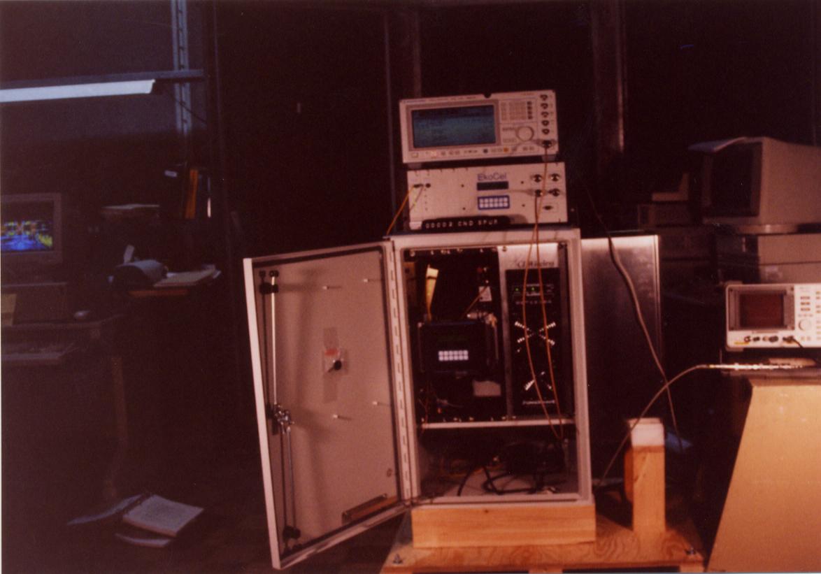
Document Text
Text extracted from the exhibit documents filed with the FCC. Open a document above to read the original.
Users Manual
CI Wireless Inc. 1211 Ira E. Woods Ave., Grapevine, TX 76051 1 TABLE OF CONTENTS 1.0 Product Description 2.0 EkoCel, System Block Diagrams 2.1 EkoCel, Hub Block Diagram 2.2 EkoCel, Microcell Block Diagram 2.3 EkoCel , HUB UNIT BLOCK DIAGRAM (W/Diversity Receive) 2.4 EkoCel , MICROCELL UNIT BLOCK DIAGRAM (Single Band) 2.5 EkoCel , MICROCELL UNIT BLOCK DIAGRAM (Dual Band HOST) 2.6 EkoCel , MICROCELL UNIT BLOCK DIAGRAM (Dual Band Slave) 2.7 EkoCel , High Power REMOTE BLOCK DIAGRAM (W/Diversity Receive 3.0 Description of EkoCel Fiber Optic Microcell System 3.1 Hub 3.2 Microcell 4.0 Description of the Hub Unit Modules 4.1 Fiber Optic Transceiver 4.2 Modem 4.3 RF Detector 4.4 4-Way Splitter/Combiner 4.5 DC/DC Converter 4.6 Hub Interconnect Module 4.7 Controller Module 4.8 AC Power Supply 4.9 Telco Modem 4.10 Duplex, Base Station Interface 4.11 Combiner Option 4.12 Cross Band Operation Option 4.13 Wave Division Multiplexer (WDM) 4.14 Optical Expansion Module 5.0 Description of the Microcell Unit Modules 5.1 Fiber Optic Transceiver 5.1bFiber Optic Slave, with Dual Transmitters and a Single Receiver 5.2 RF Modem 5.3 LNA/Driver Module 5.4 Duplexer 5.5 Lightning Arrestor 5.6 Power Amplifier Module MCA 5.7 Microcell (Remote) Control Interface Module 5.8Power Supply for High Power Remotes CI Wireless Inc. 1211 Ira E. Woods Ave., Grapevine, TX 76051 2 CI Wireless Inc. 1211 Ira E. Woods Ave., Grapevine, TX 76051 3 6.0 Identification of Hub 6.1 Front Panel Layout 6.2 Rear Panel Layout 6.3 Hub Components Layout 6.4 Optical Transceiver 6.5 Wave Division Multiplexer 6.6 System Interconnect 700-1005 Interconnect Module Board Input Connectors Controls Terminal Strip Attenuators Output to Up Link Combiner RF Inputs Input to Optical Transceiver RF Out Other 700-1001 Board 7.0 Identification of Microcell 7.1 Left Panel, A Single Band 7.2 Left Panel, Dual Band 7.3 Door Panel Microcell 7.4 Back (Heat Sink) Microcell (EKO-8) (EKO 1.9R) 7.4bBack (Heat Sink) Microcell (EKO-1.9M) 7.5 Base Bottom 7.6 Triplexer 7.7 System Interconnect 8.0 Software Control Module 8.1 Microcell (Remote) Unit Controller 8.1.1 Basic Interface 8.1.2 System Setup 8.1.3 User Settings 8.1.4 Alarms 8.2 Hub Unit Controller 8.2.1 Basic Interface 8.2.2 System Setup 8.2.3 User Settings 8.2.4 Alarms 8.3 RS 232 Port Communications 8.3.1 Terminal Interface Displays 9.0 Installation 9.1 Introduction 9.2 Getting Started 9.3 Mounting Hub Hardware 9.4 Mounting the Microcell Unit CI Wireless Inc. 1211 Ira E. Woods Ave., Grapevine, TX 76051 4 CI Wireless Inc. 1211 Ira E. Woods Ave., Grapevine, TX 76051 5 9.5 EkoCel 1.9 System Set Up Instructions 9.5.1 Down Link Set Up for EKO-8 System 9.5.2 Up Link System Set Up for the System 9.6 Calibration Table – U2 9.6.1 Calibration Table – U3 9.6.2 Calibration Table - U5 10.0 Trouble Shooting and Maintenance 10.1 Trouble Shooting Guide 10.2 Understanding Maintenance Inputs/Alarms 10.3 Module Replacement Procedures 10.4Block Diagrams with Levels Appendix A.Specifications 4 Watt 800MHz (SMR/ESMR), (Cellular) 50 Watt 800MHz (SMR/ESMR) 50 Watt 800MHz (Cellular) B.Model Number Identification (800M) E.Frequency Bands Channel Plans E1.CDMA 1.9 GHz E2.CDMA 900 MHz E3.GSM 1.9 GHz E4. IS-136 1.9 GHz F.Product Warranty CI Wireless Inc. 1211 Ira E. Woods Ave., Grapevine, TX 76051 6 CI Wireless Inc. 1211 Ira E. Woods Ave., Grapevine, TX 76051 7 EkoCel FIBER OPTIC MICROCELL SYSTEM 1.0 PRODUCT DESCRIPTION The EkoCel™ Fiber Optic Microcell System will support CDMA, PCS 1900, IS-136 or AMPS system formats. EkoCel provides system coverage enhancement by remoting the base station RF receive and transmit via a fiber optic connection to a location requiring coverage. EkoCel is designed to meet or exceed applicable base station and FCC emission standards. The EkoCel enhanced specifications provide minimal impact to the overall system performance. EkoCel is comprised of two major components the Microcell (Remote) Unit, which is remotely located in the area being provided service and the Hub Unit, which is located at the base station. EkoCel will support multiple RF channels on all PCS system formats and up to 24 channels for AMPS Cellular. Several options are available including, Wave Division Multiplexing (WDM), diversity receive, battery back up and duplex interface at the base station. EkoCel is supplied in all of the PCS bands A to F and is also available in a dual band operation configuration. The dual band unit will support both 1.9 GHz PCS and 800 MHz Cellular system over the same fiber optic cable. EkoCel is designed to meet the service provider requirements for Operations, Administration, Maintenance and Performance (OAM&P). Alarm and control of the system is accessible at the Microcell hub, remote unit or via a telephone (wire or wireless) modem connection. Relay contacts also allow the user to remote the alarms with the base station alarm system with user defined contacts. This allows the service provider to have instant alarm notification at the Network Operation Control Center (NOCC) without additional specialized hardware and software, commonly referred to as an Element Management System. This provides simplicity and cost savings to the user. Both the hub and the microcell remote are equipped with a display and function keypad allowing the user easy access to alarms and system controls without additional equipment. Three levels of security are provided to prevent unauthorized access to the system. EkoCel has a patent pending self-set up and system control feature that will allow the system to automatically set up for the user defined system requirements. EkoCel automatically adjusts gain and power based on the number of RF channels, system format, system input power and optical loss. The system continues to monitor system performance and alert the user of any system changes that requires additional real time compensation. EkoCel was developed specifically for use as a fiber optic microcell. It specifically…
Text truncated - open the document above for the full version.
Block Diagram
CI WIRELESS EKOCELL SYSTEM DIAGRAM CI WIRELESS EKOCELL HUB UNIT DIAGRAM CI WIRELESS EKOCELL REMOTE UNIT DIAGRAM
ID Label/Location Info
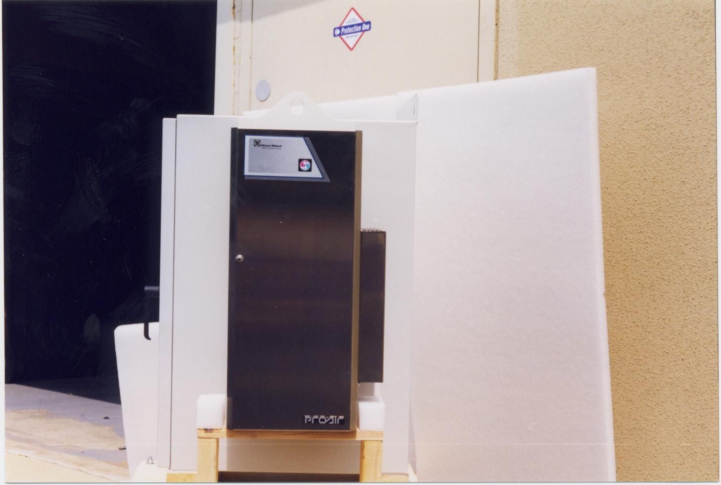
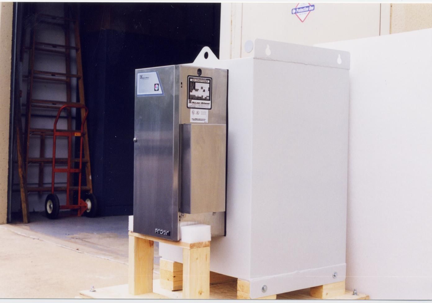
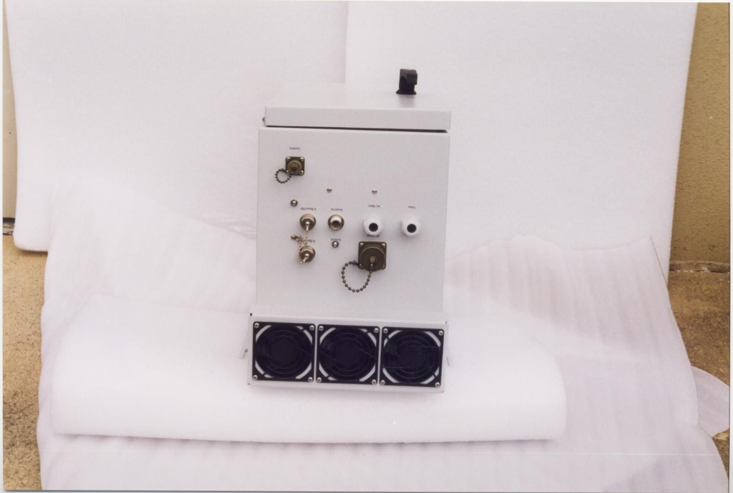
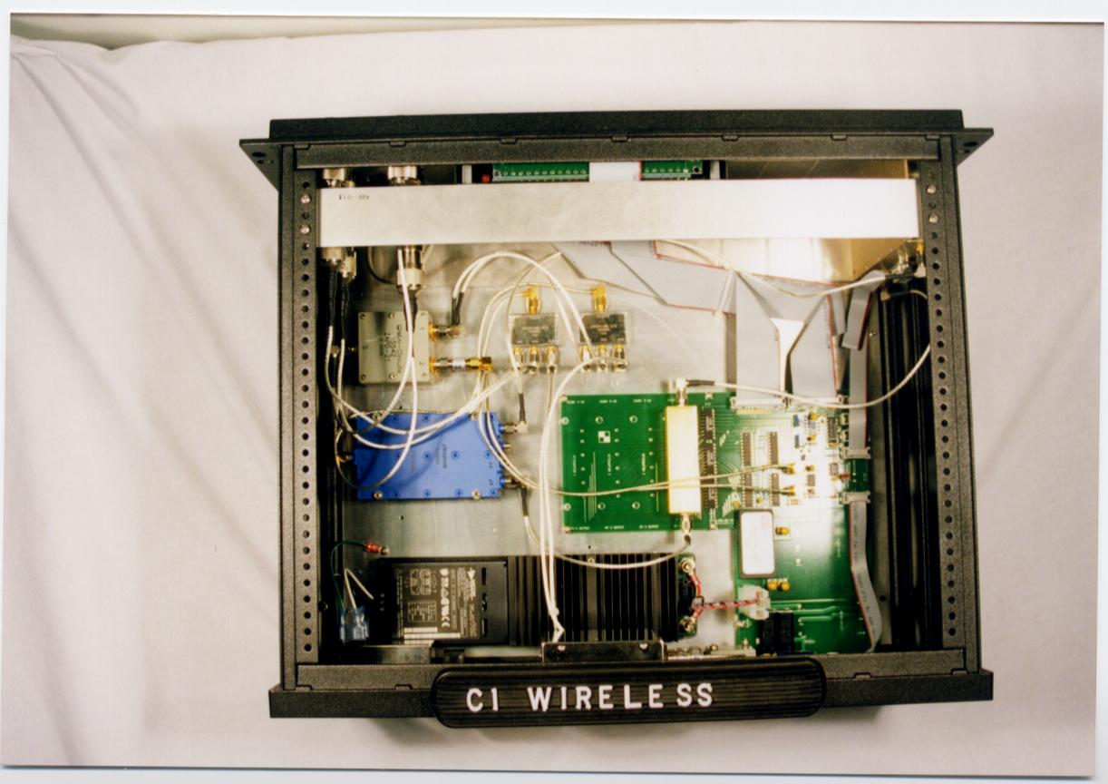
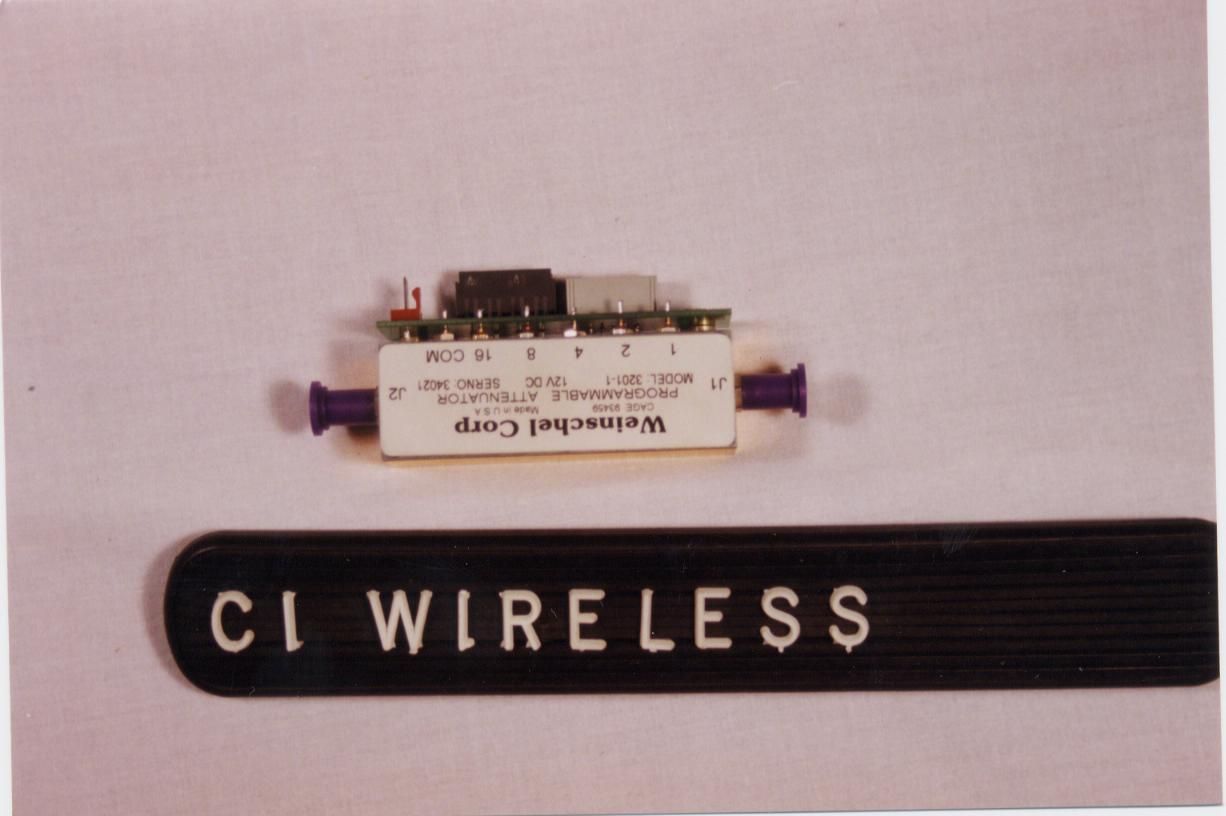
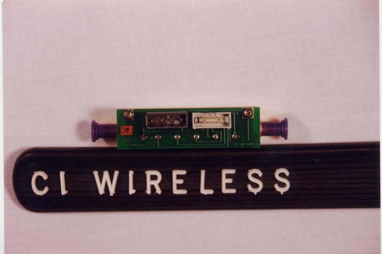
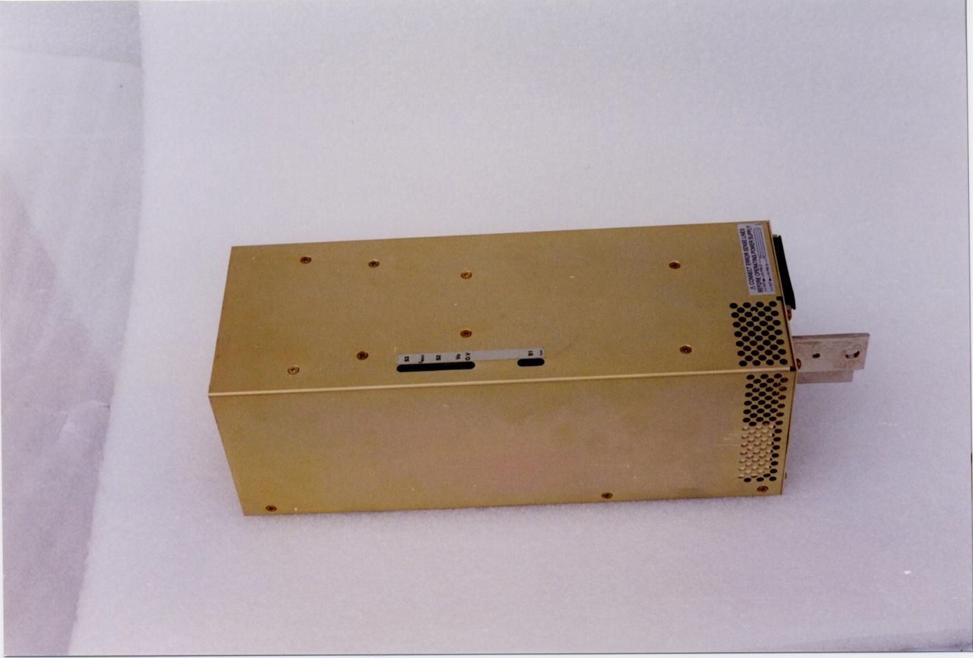
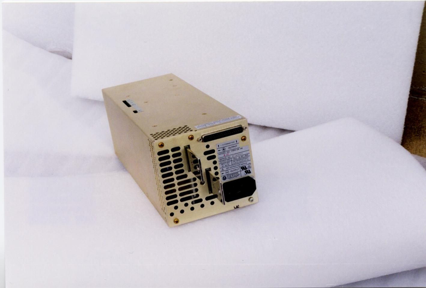
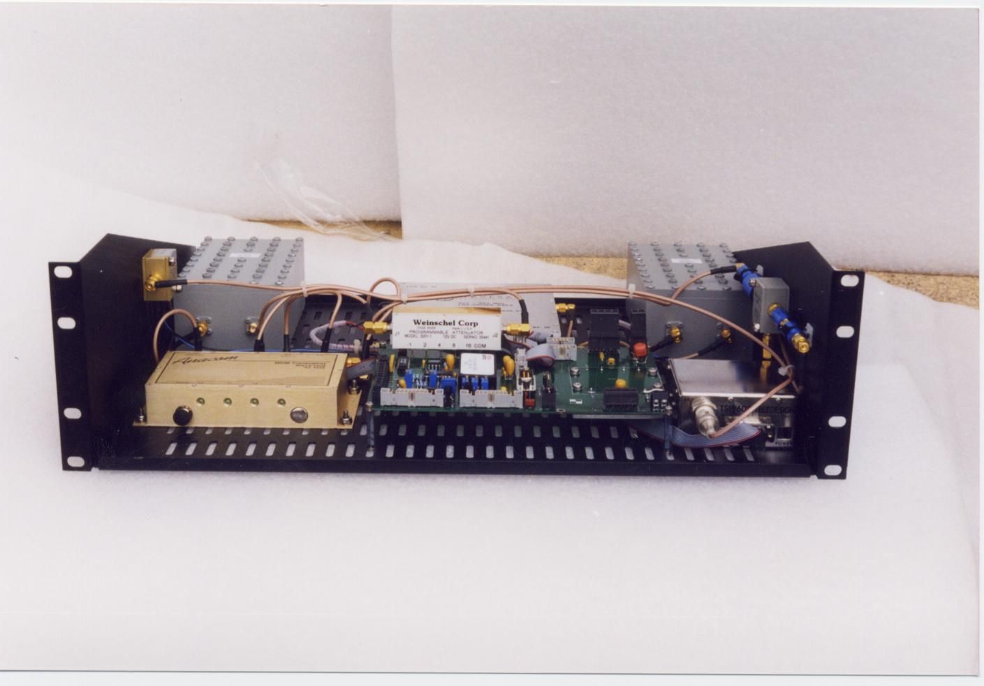
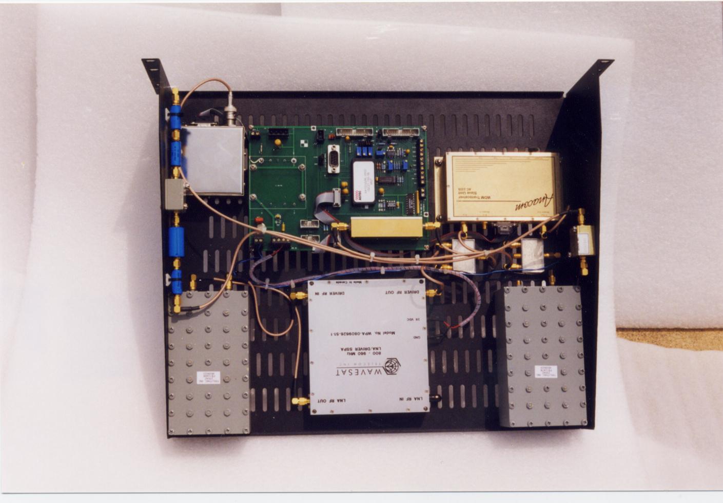
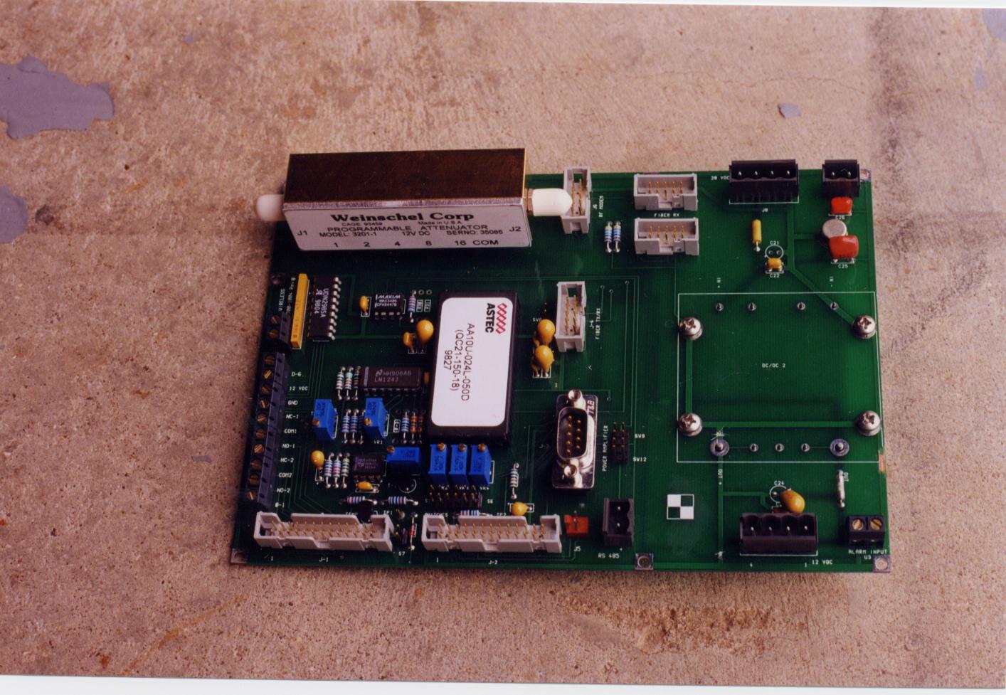
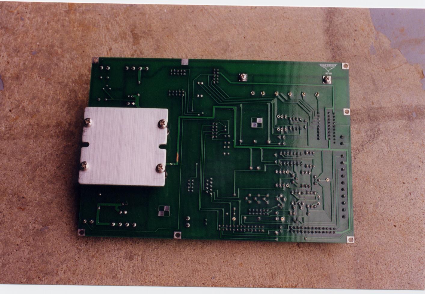
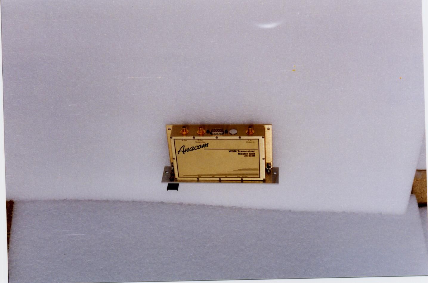
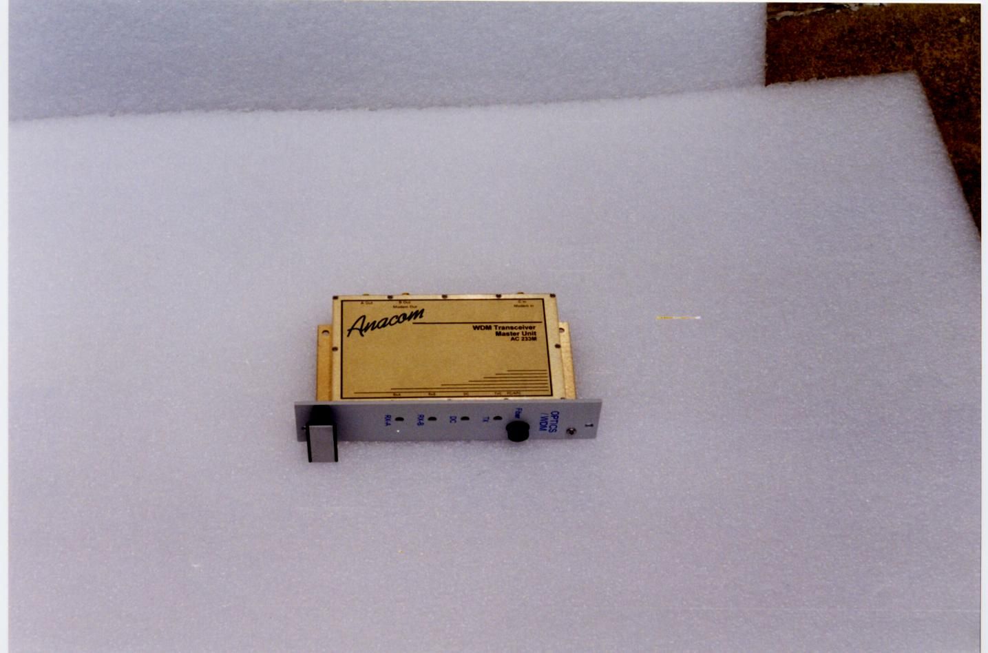
Professional Testing (EMI), Inc. Hub Unit Professional Testing (EMI), Inc. Professional Testing (EMI), Inc. Remote Unit Professional Testing (EMI), Inc.
ID Label/Location Info
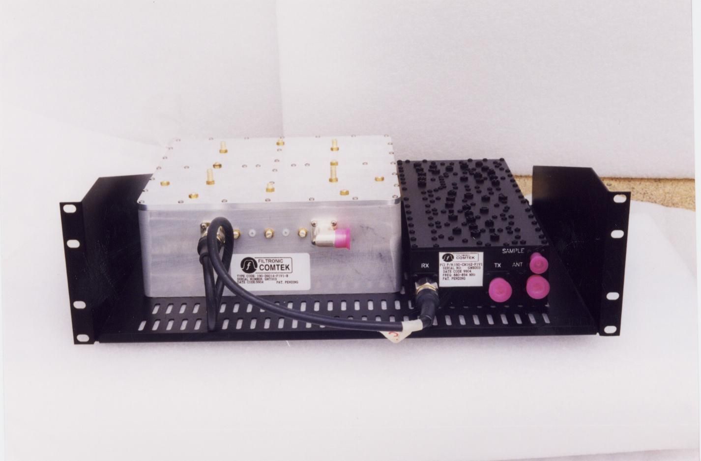
Professional Testing (EMI), Inc. Hub Unit Professional Testing (EMI), Inc. Professional Testing (EMI), Inc. Remote Unit Professional Testing (EMI), Inc.
ID Label/Location Info
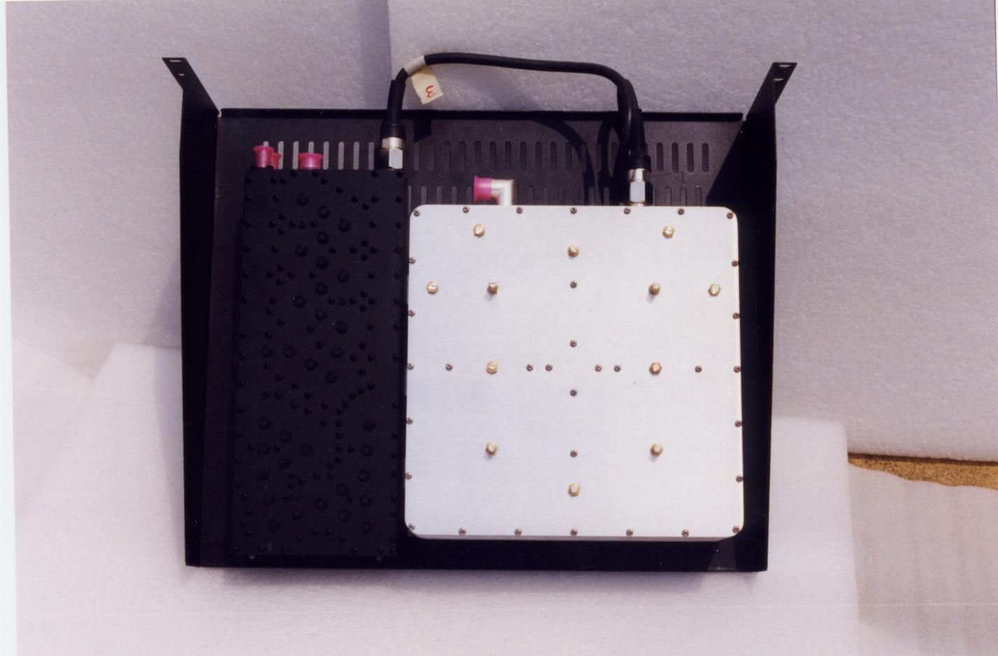
Professional Testing (EMI), Inc. Hub Unit Professional Testing (EMI), Inc. Professional Testing (EMI), Inc. Remote Unit Professional Testing (EMI), Inc.
Operational Description
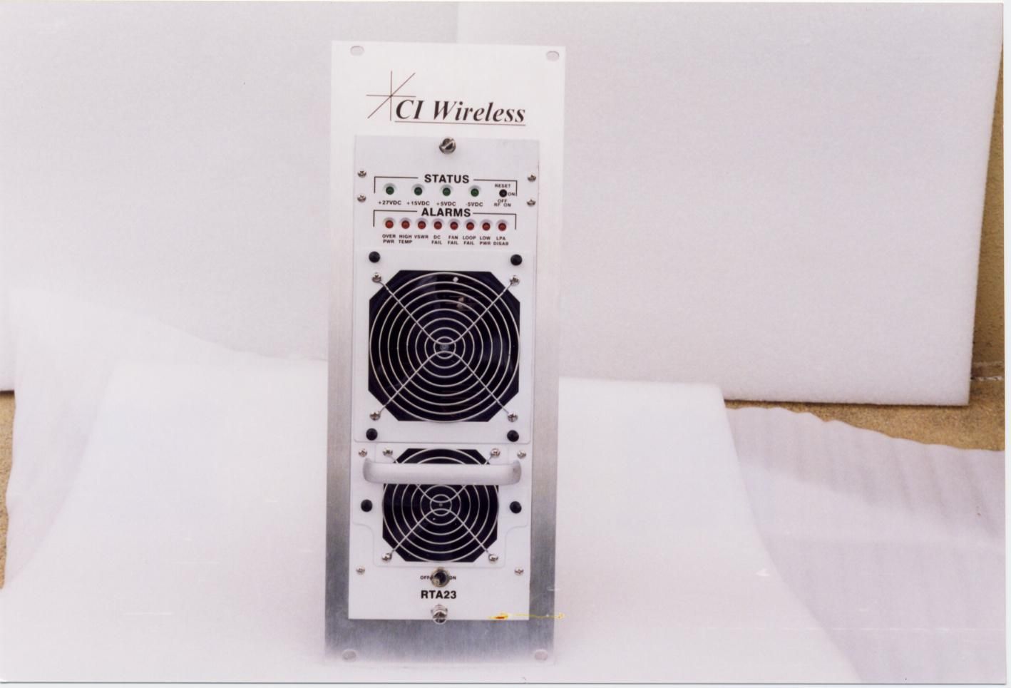
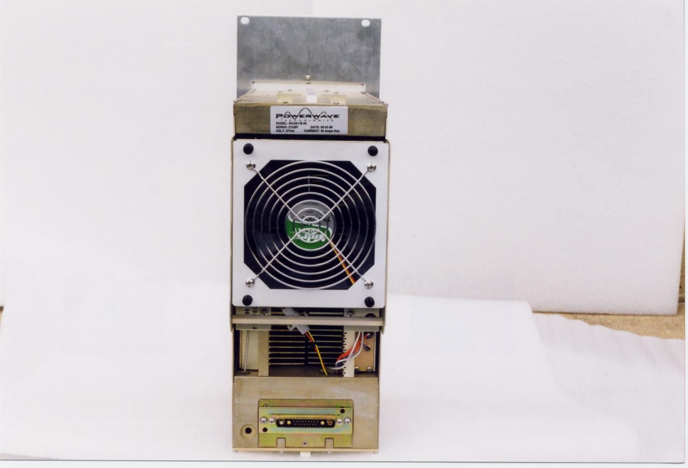
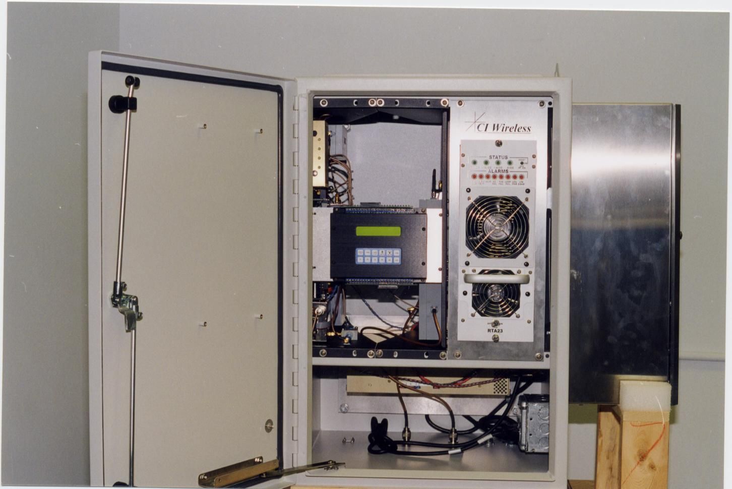
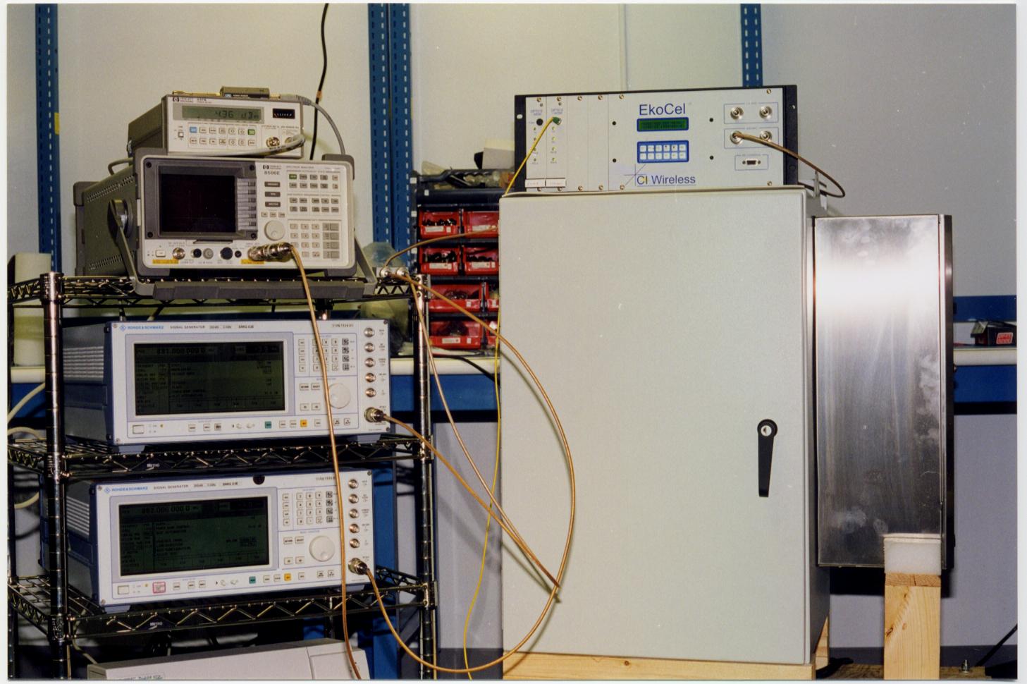
FCC ID:NUWØ5ØCEKO8 1 CI WIRELESS 800 MHZ CELLULAR BAND EKOCELL REPEATER SYSTEM DESCRIPTION OF OPERATION 1.0 BASIC DESCRIPTION The EUT is a 50 watt 800 MHz Cellular Band Repeater System. This system is a U.S. Cellular band repeater system which enhances the coverage of a cellular system by adding base station capability to traditional poor cellular coverage areas (i.e. subways, shopping malls, convention centers). The system has a set of automatic setup features, enabling the repeater to be installed & configured by one person. Automatic system monitoring is present to monitor system health & report/record any EUT problems. The CI Wireless 800 MHz Cellular Band 50 watt Repeater supports CDMA, TDMA and AMPS communications in the U.S. cellular band. The EkoCell system is comprised of two components: a Hub unit and a Remote unit. The Hub is installed at a cellular base station while the remote unit is installed at the desired transmit/receive location and attached to an antenna assembly. The two pieces are connected by two fiber optic links (one for transmit, one for receive). Due to the low loss of the fiber link, the Remote is usually not installed at the same location as the Hub unit. 2.0 RF THEORY OF OPERATION The CI Wireless 800 MHz Cellular Band 50 watt Repeater operates in two basic modes of operation simultaneously: transmit and receive. When installed, the Hub portion of the EkoCell is connected in to a standard base station for the cellular system. The Remote Unit is then installed at a location up to 10 kilometers away from the base station. In the transmit mode of operation, the Hub taps the RF signals from the base, routes the signals through an RF modem, then feeds the output of the RF modem into a fiber optic modulator. The fiber optic modulator contains a solid state laser and optic receiver. The output of the laser is fed via a multimode fiber optic cable to the Remote Unit. When the signal arrives at the Remote Unit, the signal is received by another fiber optic modulator, fed to an RF Modem, then routed to an amplifier. The output of the power amplifier is regulated to maintain a 50 watt output level. The output of the amplifier is fed to a duplexer (with lightning protection) then to the antenna port for transmission. In the receive mode of operation, the mobile signals are received from the antenna port on the Remote Unit, routed through the duplexer, then boosted and filtered by a low noise amplifier/band pass filter assembly. This signal is modulated by the RF modem, fed to the Remote Unit fiber optic modulator, then transmitted back to the Hub Unit. The Hub Unit receives the optical signal and reconstitutes the original mobile signal. This signal is then fed to the base station circuitry. The system does perform RF pre-emphasis on the signals to correct for transmission losses. FCC ID:NUWØ5ØCEKO8 2 3.0 SYSTEM CONFIGURATION(S) The two models for the system components tested are: Hub Unit:Eko-8H0B0-DB0000 Remote Unit:Eko-8M0CR-DAC000 The test covered under this report address all subseries of these models. The base model designators for the components of this system are Model Eko-8HXB0-XXXXXX for the Hub unit and Model Eko-8MXCR-XXXXXX for the Remote Unit. See attached sheet for model designator definitions. The two particular models used for this test were loaded with all active circuit options available, providing a worst case configuration for emissions testing. FCC ID:NUWØ5ØCEKO8 3 CONFIGURATION INDEX
Test Report
FCC ID# NUWØ5ØCEKO8 FCC ID: NUWØ5ØCEKO8 Prepared for: CI WIRELESS INC. 1211 Ira E. Woods Avenue Grapevine, Texas 76051 By: Professional Testing (EMI), Inc. 1601 FM 1460, Suite B Round Rock, Texas 78664 Submitted to: Federal Communications Commission Equipment Approval Services P.O. Box 358315 Pittsburgh, Pennsylvania 15251-3315 June 1999 FCC Application for Certification of an Intentional Radiator CI WIRELESS INC. EkoCell 800 MHz Cellular Band 50 Watt Repeater (Transmitter Portion) FCC ID# NUWØ5ØCEKO8 Professional Testing (EMI), Inc.2 of 63 Table of Contents Title Page ..............................................................................................................................................1 Table of Contents...................................................................................................................................2 Certificate of Compliance......................................................................................................................3 1.0 Equipment Under Test (EUT) Description ..................................................................... 5 2.0 Occupied Bandwidth Measurements............................................................................... 6 2.1 Test Procedure................................................................................................................. 6 2.2 Test Criteria..................................................................................................................... 6 2.3 Test Results ..................................................................................................................... 7 3.0 Effective Radiated Power (ERP) Measurements............................................................. 7 3.1 Test Procedure................................................................................................................. 7 3.2 Test Criteria..................................................................................................................... 7 3.3 Test Results ..................................................................................................................... 8 4.0 Out of Band Emissions - Radiated .................................................................................. 8 4.1 Test Procedure................................................................................................................. 8 4.2 Test Criteria..................................................................................................................... 9 4.3 Test Results ..................................................................................................................... 9 5.0 Out of Band Emissions - Conducted ............................................................................. 10 5.1 Test Procedure...............................................................................................................10 5.2 Test Criteria................................................................................................................... 10 5.3 Test Results ................................................................................................................... 11 6.0 Radiofrequency Radiation Exposure Evaluation .......................................................... 11 6.1 Evaluation Procedure .................................................................................................... 11 6.2 Evaluation Results......................................................................................................... 12 7.0 Three Signal Intermodulation Test................................................................................ 12 8.0 Form 731 Information ................................................................................................. 123 8.1 Emission Designator ..................................................................................................... 13 8.2 Output Power.................................................................................................................14 8.3 Output Power Ratings for Multi-Channel Operation .................................................... 15 8.4 Frequency Band of Operation ....................................................................................... 15 8.5 Grant Notes ................................................................................................................... 15 9.0 Modifications ................................................................................................................15 10.0 List of Test Equipment .................................................................................................. 15 Appendices Appendix A - Sub-Model Index Data .................................................................................................17 Appendix B - Occupied Bandwidth Test Data....................................................................................19 Appendix C - Effective Radiated Power (ERP) Test Data .................................................................26 Appendix D - Out of Band Emissions - Radiated Test Data ..............................................................28 Appendix E - Out of Band Emissions - Conducted Test Data ...........................................................47 Appendix F – Intermodulation Product Data Sheets ..........................................................................57 FCC ID# NUWØ5ØCEKO8 1601 FM 1460, Suite B Round Rock, Texas 78664 512/244-3371 Fax 512/244-1846 Applicant:CI Wireless Inc. Applicant’s Address:1211 Ira E. Woods Avenue Grapevine, Texas 76051 Model:800 MHz Cellular Band 50 Watt Repeater Serial Number:H919005/M919009 Project Number:00002-10 Test Dates:June 7, 8, 9 and 10, 1999 I, Jeffrey A. Lenk, for Professional Testing (EMI), Inc., being familiar with the FCC rules and test procedures have reviewed the test setup, measurement data and this report.…
Text truncated - open the document above for the full version.
Contact Information
Applicant
Richard E Kent(Assistant General Counsel)
Technical Contact
CI Wireless, Inc.David L McKay
[email protected]817-416-0583
1121 Ira E. Woods Ave. · Grapevine, Texas · United States
Non-Technical Contact
CI Wireless, Inc.David L McKay
[email protected]817-416-0583
Test Firm
Professional Testing (EMI) Inc.Jeffrey Lenk
Technical Specifications
| # | Rule Parts | Frequency Range | Power Output | Emission |
|---|---|---|---|---|
| 3 | 22.901(d) | 869 MHz - 894 MHz | 50 W | DXW |
Other Applications from EMS Technologies Inc
NUW0A1MINI19
Feb 13, 20001900 MHz PCS Repeater
Equipment Class
AMP - Amplifier
NUW008CMIR8
Feb 06, 2000Cellular Repeater
Equipment Class
AMP - Amplifier
NUW050SEKO8
Oct 04, 1999ESMR Antenna Extender
Equipment Class
AMP - Amplifier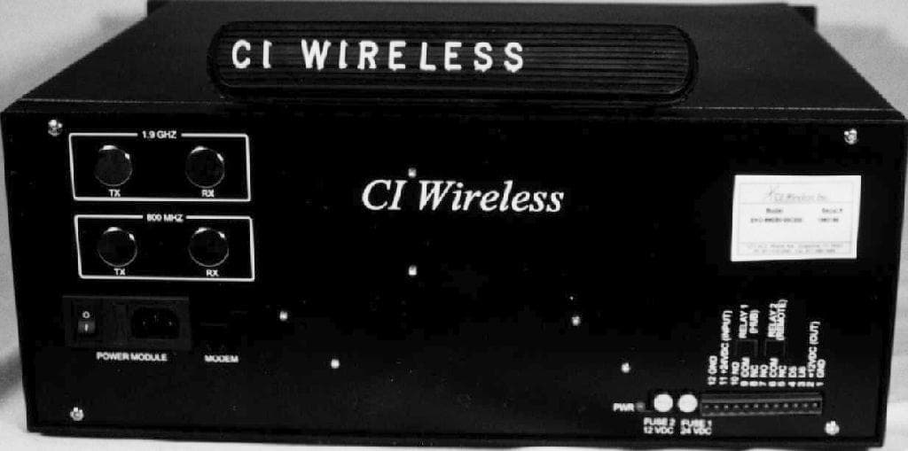
NUW004SEKO8
Apr 25, 1999800 MHz ESMR Band EkoCell Repeater
Equipment Class
AMP - Amplifier
NUW008EKO19
Apr 25, 19991900 MHz PCS Band 8 Watt Repeater
Equipment Class
AMP - Amplifier