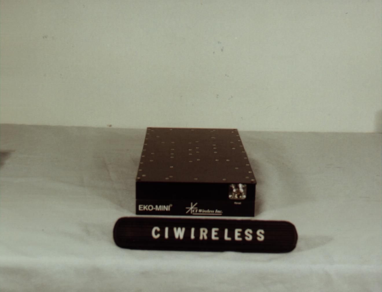
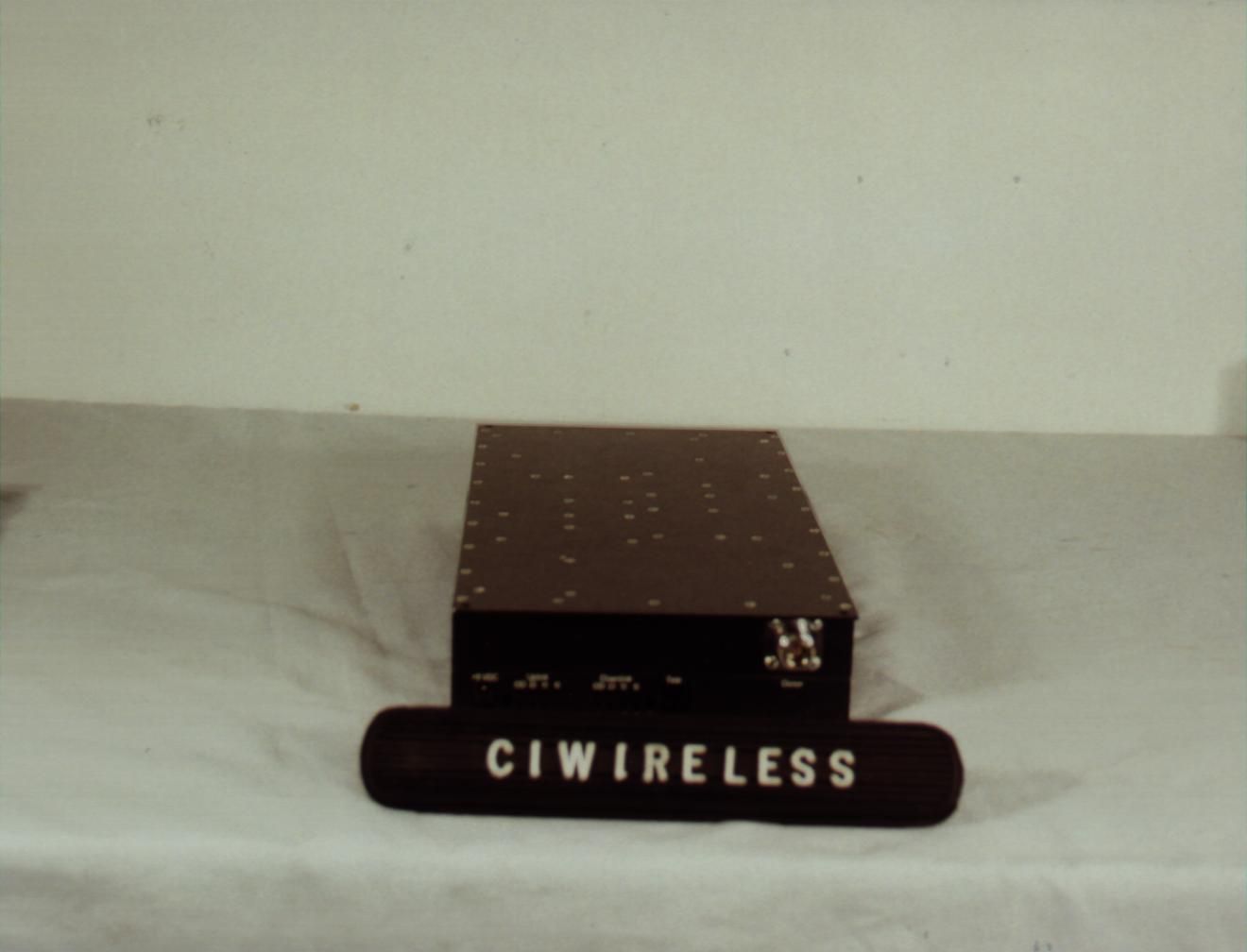
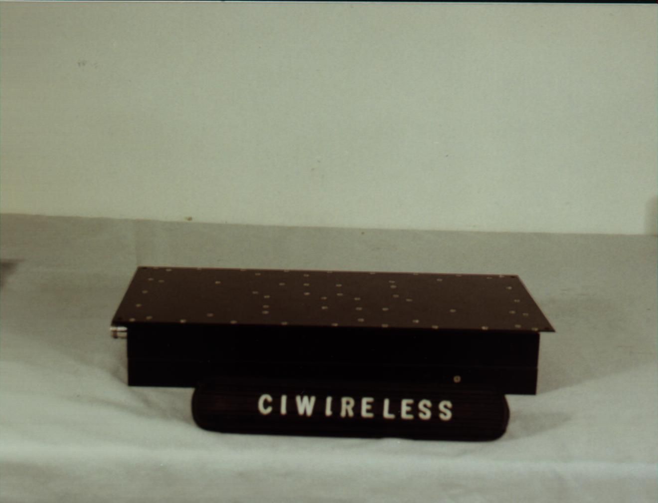
NUW0A1MINI191900 MHz PCS Repeater
EMS Technologies Inc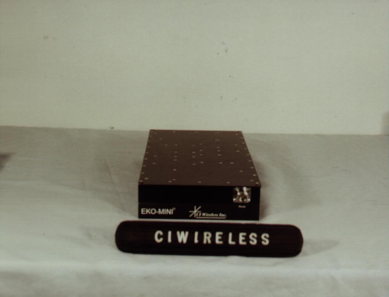
Click to zoom
Application Details
- Equipment Class
- AMP - Amplifier
- Date of Grant
- Feb 13, 2000
- Application Purpose
- Original Equipment
- Date of Application
- Nov 29, 1999
- Equipment Note
- 1900 MHz PCS Repeater
- Frequency Range
- 1930.00000000 - 1990.00000000
- Company
- EMS Technologies Inc
- Country
- United States
Documents & Files
Document Text
Text extracted from the exhibit documents filed with the FCC. Open a document above to read the original.
Users Manual
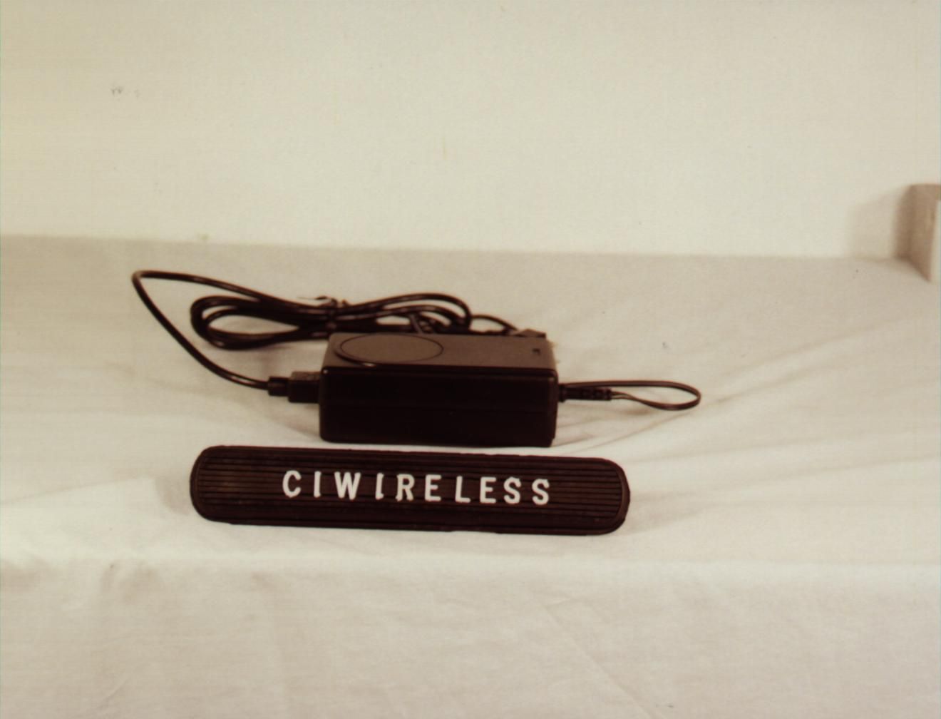
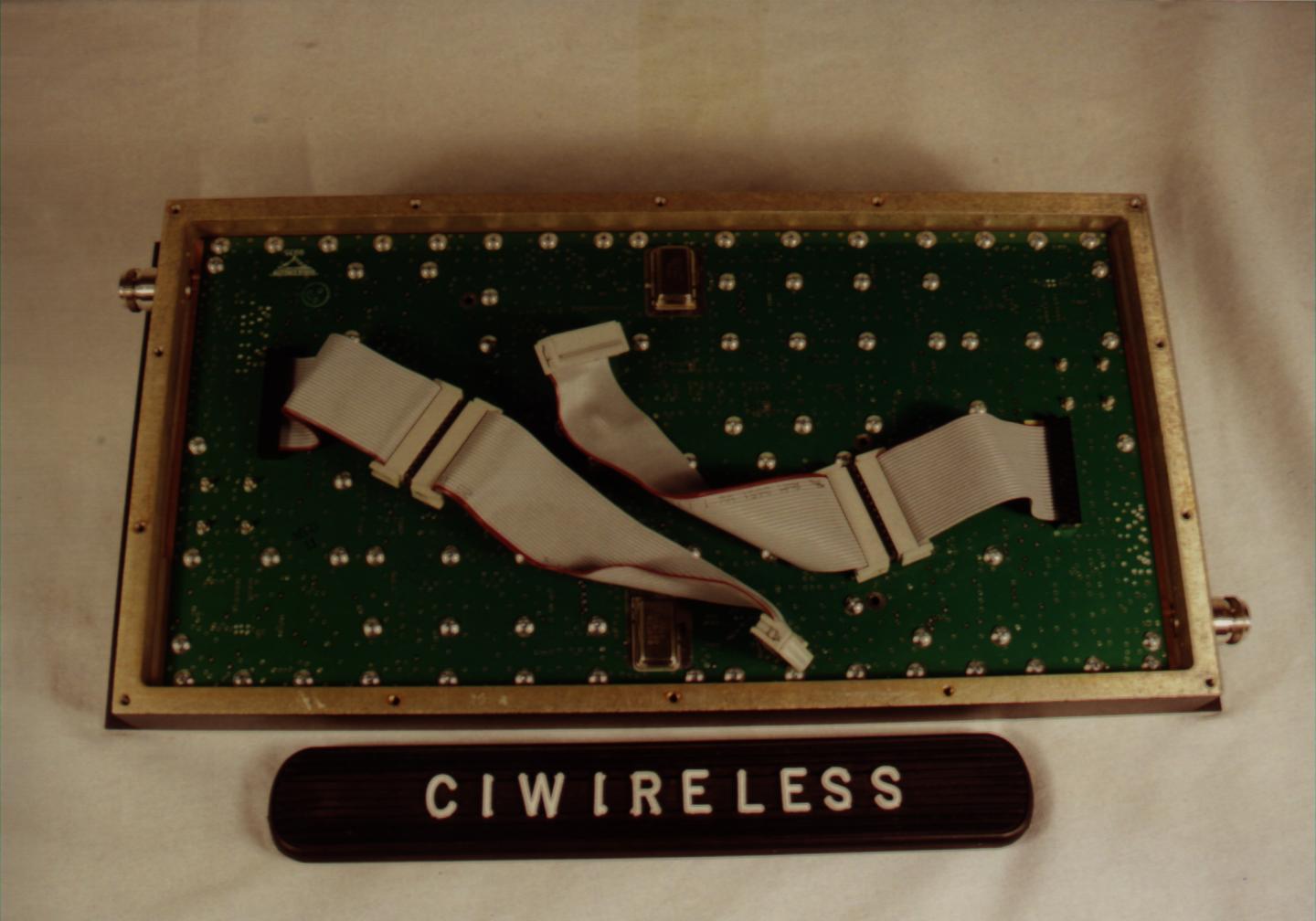
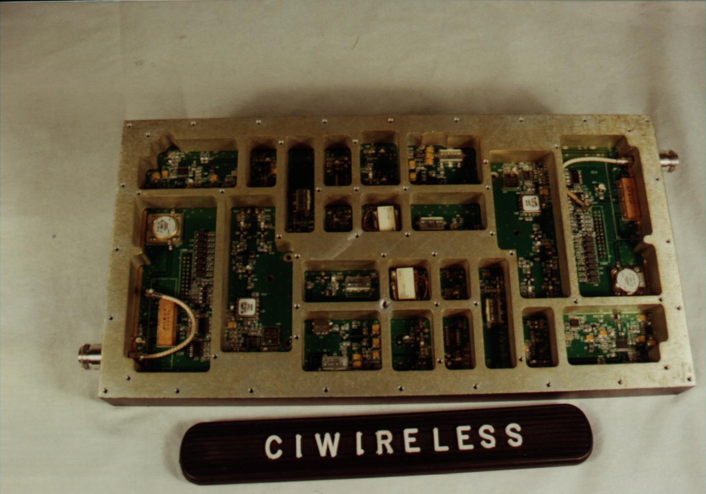
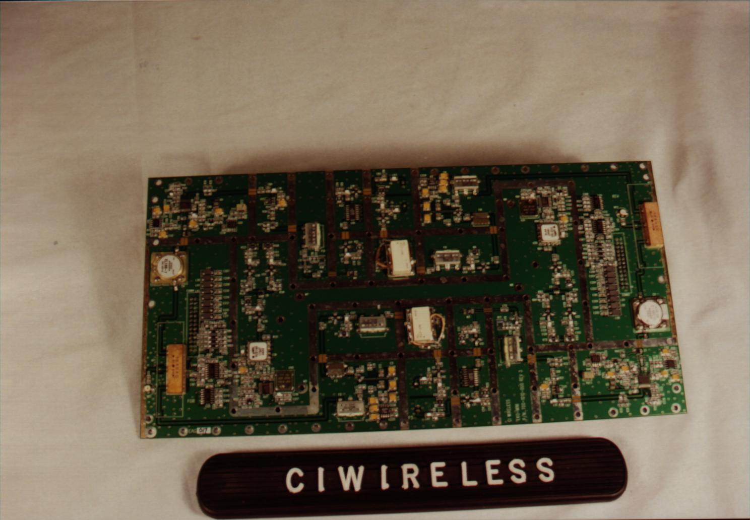
Preliminary Document CI Wireless Inc.11/19/991 Eko-MiniManual Description The Eko-Mini is a band selective, bi-directional amplifier unit and was designed to provide enhanced RF coverage for wireless systems in small facilities. Usage includes providing coverage in retail stores, offices, warehouses, restaurants, homes, etc. The Mini is housed in an indoors mountable enclosure, and is powered with a regulated wall mountable power supply. The Mini supports most system protocols including CDMA, GSM/PCS1900 and TDMA and is available in models that cover all licensed 1.9 GHz PCS bands A through F, ESMR/SMR 806-866 MHz and Cellular 821 to 894 MHz. Band selective filtering in both uplink and downlink signal paths is accomplished with down conversion to an intermediate frequency and SAW filtering to provide maximum selectivity from out of band carriers. The Mini features Auto set-up, lightweight compact enclosure, optional remote alarming, excellent electrical specifications, high reliability and cost effective pricing. Functionality The Mini is capable of automatically adjusting its own signal gain levels up to the maximum output power levels. The Mini detects the downlink output power and adjusts the level for 20- dBm composite output power and continues to monitor and reset the gain as required for proper system performance. For example, when CDMA protocol system is being amplified, there could be an error in set up initially resulting from only pilot sync, and paging Walsh codes being present on the RF carrier. The Mini will reduce the system gain until no signal is received that will exceed the output power setting. This prevents the Mini from setting up to a higher in power level than actually desired if all of the Walsh codes were present. The gain does not continually change to maintain an output power of 20 dBm (AGC) since this would defeat and fight the benefits of power control in the system. The user may reduce or limit the power output level by adjusting the peak power limit as described below. The user peak power switches will set the unit’s output power up to 14 dB below the maximum power output of 20 dBm the user interface to control this feature is the peak power switches. The Mini has 30 dB of gain control in the uplink and downlink signal paths. This gain is controlled by two methods. Up to 14 dB can be controlled by adjusting the user peak limit switches located behind an access plate on the side of the unit to limit the maximum output power level. The uplink and downlink attenuators are controlled by the internal microprocessor to adjust the maximum gain of the unit for both paths. The uplink and dowlink signal paths are adjusted to the same setting by the microprocessor unless the user offsets, reduces the gain in the uplink signal path. The user has control to reduce the uplink gain by 6 dB, this can be used to balance the uplink and downlink paths as well as reduce contribution of noise to the base station receivers. Preliminary Document CI Wireless Inc.11/19/992 Downlink Peak Power Limit Switches Power Limit (dBm)SixSevenEight 20offoffoff 18onoffoff 16offonoff 14ononoff 12offoffon 10onoffon 8offonon 6ononon Uplink Gain Offset, reduces uplink gain Gain Offset (dBm)OneTwo 0offoff -2onoff -4offon -6onon If a unit is moved from one location to another pressing the reset switch will restart the automatic set up feature. If the peak limit and uplink gain offset switches are preset when the unit is installed the mini will first attempt to set itself up to the full RF output power of 20 dBm and then reduce power as instructed by the peak limit and uplink gain offset switches. The Mini has a total of 30 dB of gain control in the uplink and downlink signal paths which is controlled by the microprocessor. The microprocessor monitors the up link and down link detected signal levels and adjusts the gain to prevent overdriving the linear power amplifier circuits. The mini monitors the downlink detected signal and adjusts the gain to achieve rated output power, 20 dBm. The uplink attenuation is adjusted by the microprocessor to the same gain level. Path loss is normally equal in both directions. The microprocessor continues to monitor the detected output power on both paths to prevent overdrive. Should the downlink detected power increase above the desired level, the processor will reduce the gain in both up link and down link paths. A subscriber unit getting very close to the rerad antenna, may causes uplink signal overdrive. The processor will temporarily reduce the gain in the up link (reverse) path when uplink signal overdrive is sensed, which will reduce the coverage during this condition. Proper placement of the rerad antenna will reduce the occurrence of this condition. The output power level setting and the maximum detected level, along with date and time, are recorded in the history log file. Preliminary Document CI Wireless Inc.11/19/993 Protocol Selection To insure proper RF power output the proper protocol must be selected this insures the software will properly distinguish the detected RF power level. CDMA is the only protocol that requires a different look up table/RF calibration. Protocol SelectionSwitch Five CDMAOn All Other*Off *All other protocols include; AMPS, GSM, PCS 1900, CDMA, IDEN, ESMR, TDMA Band Selection The Mini is available in two models, a 15 Mhz bandwidth unit and a 5 Mhz bandwidth unit. Selection of the proper operating band A, B, or C with the 15 Mhz unit and D, E, or F with the 5 Mhz model is user selectable with two dip switches as follows: Band SelectionBand WidthSwitch 3Switch 4 A 15 off off B 15 on off C 15 off on D 5 off off E 5 on off F 5 off on If the switches are improperly set (On/On), the unit will not function. This fault will be indicated by the DC power on LED Indicator flashing green. Note: If the band selection switch is changed after the unit is powered up the unit will not change frequency until the (1) power is cycled or (2) the r…
Text truncated - open the document above for the full version.
Block Diagram
Block Diagram CI Wireless Inc. Mini-EkoCell 1900 MHz PCS Band Repeater FCC ID: NUW0A1MINI19 Downlink Uplink
ID Label/Location Info
Professional Testing (EMI), Inc. 15 MHz Unit Professional Testing (EMI), Inc. 5 MHz Unit Professional Testing (EMI), Inc.
Operational Description
Theory of Operation Eko-Mini 1.9 The Eko-Mini 1.9A is a radio frequency repeater for use in the 1.9 GHz PCS spectrum. It is capable of operating in all PCS bands (A through F) and is not dependent on the over the air protocol selected by the user. The downlink frequency band is from 1930 MHz to 1990 MHz. The uplink frequency band is from 1850 MHz to 1910 MHz. In the IF, the downlink and uplink bandwidths are set by selecting the appropriate SAW filter, either 15 MHz for A, B, and C bands or 5 MHz for D, E, and F bands. Both down conversion to the 140 MHz IF and up conversion to the original carrier frequency are referenced to the same local oscillator. Therefore the frequency stability of the Eko-Mini 1.9A is the same as that received from the base station and the connected mobile. Overall system gain is 70 dB. The maximum output is limited to +20 dBm composite. Radio frequency input first passes through the downlink portion of the duplexer and a bandpass filter. It is then amplified by a Low Noise Amplifier with approximately 15dB of gain. The signal then passes through two stages each consisting of a bandpass filter and a 10dB amplifier. These stages provide one input to the downlink mixer. The local oscillator provides the other input. This input is 140 MHz below the received frequency. The 140 MHz intermediate frequency is then fed through a low pass filter to limit unwanted carrier products. The signal is then amplified and passes through the appropriate SAW Filter to assure the proper bandwidth. It is then amplified and applied to software selectable attenuators for output level limiting. The signal is then amplified and upconverted to the carrier frequency. It is then input to the driver, power amplifier, isolator, and duplexer. The output power limit is user selectable in two dB steps from a maximum of +20 dBm down to +6 dBm on the downlink. The user can select up to six dB of additional attenuation, in two dB steps, in the uplink. The uplink path is identical to the downlink path with carrier frequency offset by the PCS standard 80 MHz. The same L. O. is used for both down conversion and up conversion. Therefore the frequency stability of the path will be the same as that of the interfering mobile. Remote alarms are provided through a previously certified Cermatek dial up modem. Alarms include both uplink and downlink synthesizer unlock conditions, PA overdrive, loss of the downlink source, and internal voltage failure. Essential alarms will result in the unit inhibiting both the uplink and downlink power amplifiers. Visual alarm indications are also provided locally.
Test Report
FCC ID# NUWØA1MINI19 FCC ID: NUWØA1MINI19 Prepared for: CI WIRELESS INC. 1211 Ira E. Woods Avenue Grapevine, Texas 76051 By: Professional Testing (EMI), Inc. 1601 FM 1460, Suite B Round Rock, Texas 78664 Submitted to: Federal Communications Commission Equipment Approval Services P.O. Box 358315 Pittsburgh, Pennsylvania 15251-3315 December 1999 FCC Application for Certification of an Intentional Radiator CI WIRELESS INC. Mini-EkoCell 1900 MHz PCS Band Repeater (Transmitter Portion) FCC ID# NUWØA1MINI19 Professional Testing (EMI), Inc.2 of 176 Table of Contents Title Page ...............................................................................................................................................1 Table of Contents....................................................................................................................................2 Certificate of Compliance.......................................................................................................................3 1.0Equipment Under Test (EUT) Description............................................................................................5 2.0Occupied Bandwidth Measurements....................................................................................................6 2.1Test Procedure....................................................................................................................................7 2.2Test Criteria........................................................................................................................................7 2.3Test Results.........................................................................................................................................7 3.0Effective Radiated Power (ERP) Measurements...................................................................................7 3.1Test Procedure....................................................................................................................................8 3.2Test Criteria........................................................................................................................................8 3.3Test Results.........................................................................................................................................8 4.0Out of Band Emissions - Radiated.......................................................................................................8 4.1Test Procedure....................................................................................................................................9 4.2Test Criteria........................................................................................................................................9 4.3Test Results.........................................................................................................................................9 5.0Out of Band Emissions - Conducted...................................................................................................11 5.1Test Procedure..................................................................................................................................11 5.2Test Criteria......................................................................................................................................11 5.3Test Results.......................................................................................................................................11 6.0Radiofrequency Radiation Exposure Evaluation................................................................................12 6.1Evaluation Procedure........................................................................................................................12 6.2Evaluation Results.............................................................................................................................12 7.0Frequency Stability Test..................................................................................................................142 8.0Three Signal Intermodulation Test ..................................................................................................143 9.0Form 731 Information......................................................................................................................143 9.1Emission Designator..........................................................................................................................14 9.2Output Power.....................................................................................................................................16 9.3Frequency Band of Operation............................................................................................................16 9.4Grant Notes.......................................................................................................................................16 10.0Modifications.....................................................................................................................................16 11.0List of Test Equipment.......................................................................................................................16 Appendices Appendix A – Data Sheet of Two Filters..............................................................................................18 Appendix B - Occupied Bandwidth Test Data......................................................................................21 Appendix C - Equivalent Isotropically Power (ERP) Test Data..........................................................94 Appendix D - Out of Band Emissions - Radiated Test Data...............................................................101 Appendix E - Out of Band Emissions - Conducted Test Data............................................................103 Appendix F – Intermodulation Product Test Data......................................…
Text truncated - open the document above for the full version.
Contact Information
Applicant
Richard E Kent(Assistant General Counsel)
Technical Contact
CI WirelessHarold Miller
[email protected]817-416-0583
1211 Ira E. Woods Avenue · Grapevine, Texas · United States
Non-Technical Contact
CI WirelessHarold Miller
[email protected]817-416-0583
Test Firm
Professional Testing (EMI) Inc.Jeffrey Lenk
Technical Specifications
| # | Rule Parts | Frequency Range | Power Output | Emission | Tolerance |
|---|---|---|---|---|---|
| 6 | 24E | 1.93 GHz - 1.99 GHz | 100.00 mW | GXW | % |
Other Applications from EMS Technologies Inc
NUW008CMIR8
Feb 06, 2000Cellular Repeater
Equipment Class
AMP - Amplifier
NUW050CEKO8
Dec 09, 1999Cellular Repeater
Equipment Class
AMP - Amplifier
NUW050SEKO8
Oct 04, 1999ESMR Antenna Extender
Equipment Class
AMP - Amplifier
NUW004SEKO8
Apr 25, 1999800 MHz ESMR Band EkoCell Repeater
Equipment Class
AMP - Amplifier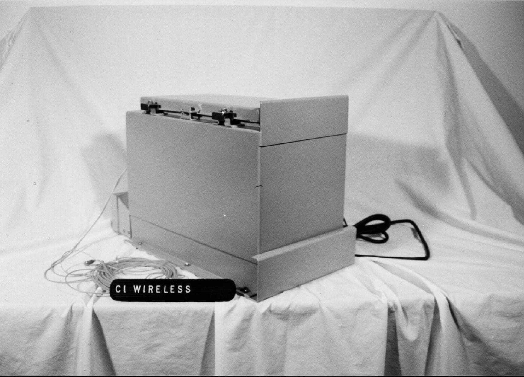
NUW008EKO19
Apr 25, 19991900 MHz PCS Band 8 Watt Repeater
Equipment Class
AMP - Amplifier