NW71023HD Sports Video Camera Camera/iON Air Pro 2 WiFi/ Air Pro 2 WiFi/Gen 2 with WiFi
World Wide Licenses Ltd.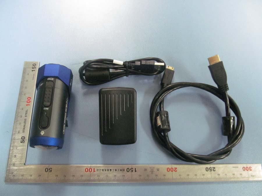
Click to zoom
Application Details
- Equipment Class
- DTS - Digital Transmission System
- Date of Grant
- Feb 07, 2013
- Application Purpose
- Original Equipment
- Date of Application
- Feb 07, 2013
- Equipment Note
- HD Sports Video Camera Camera/iON Air Pro 2 WiFi/ Air Pro 2 WiFi/Gen 2 with WiFi
- Frequency Range
- 2422.00000000 - 2452.00000000
- Company
- World Wide Licenses Ltd.
- Country
- China
Documents & Files
Document Text
Text extracted from the exhibit documents filed with the FCC. Open a document above to read the original.
Users Manual
Thank you for purchasing the iON Air Pro 2 HD sports video camera. This QSG contains the common functions and features of Air Pro 2 and Air Pro 2 Wi-Fi. For additional features and functi ons of Air Pro 2 Wi-Fi, please refer to the back part of the manual. The iON Air Pro 2 can be mounted with the Bike & Helmet Kit or the Board Kit for the ultimate adventure HD recording experience. Getting to know your camera Common features: 9 iON Air Pro 2 is a Professional, High Quality Digital Video Recorder that records Full HD videos with the flip of an an easy slide switch 9 It has the latest 14 Mega Pixel Sensor for you to take great digital photographs 9 A 180 degree high quality lens provides a super wide angle field of view 9 Your camera supports a MicroSD card up to 32GB, allowing you to take videos in 1080p with 30 frames per second for approximately 4 Hours. 9 Equipped with the microphone jack for connection with an external microphone.* 9 The Waterproof Housing enables you to operate the camera up to 10 meters under water. 9 iON Air Pro 2 is about 4.51 ounces or 128g. * When an external microphone (not included) is connected, audio cannot be recorded through the built-in microphone. 1. Package Contents of Air Pro 2 Carefully unpack the package and ensure that you have the following items: 2. Functional Parts of Air Pro 2 1 Power 1. Turns the camera on or off 2. Takes a single photograph 2 LED Indicator Shows the camera status 3 Recording Slide Switch Slide to start or stop video recording 4 Lens High quality lens 5 MicroSD Card Slot MicroSD card storage location. 6 Mic Jack To enable you to connect to an external microphone (not included) 7 Mini HDMI Jack To enable you to connect the camera to an HDTV with an HDMI cable (not included) 8 Video Resolution Switch Select video resolution: FHD (Full HD) or HD. 9 USB Port 1. Connect to your computer for data transfer or camera setup 2. Charge your camera 10 Reset Button Reset the camera 11 PODZ Socket Connect the PODZ to the camera to perform additional functions 3. Using Your Camera 3.1 Charging up Your Camera Charge your camera with either the USB cable or AC/DC adapter. The red LED will light up to indicate the camera is charging and it will turn off once the camera has been fully charged. It takes about 3 hours to fully charge the camera. 3.2 Inserting a Memory Card Insert a MicroSD card up to 32GB (not included) before using your camera. Ensure that the camera power is turned OFF before inserting the card into the slot. Notes: 1. There is only one correct direction to insert the MicroSD card into the slot. Do not force the card into the card slot as it may damage both the camera and the MicroSD card. 2. A new MicroSD card should be formatted before using. For more information, please see section 4.2. 3. We recommend a class 10 SDHC card. 3.3 Setting up Date and Time Connect your camera to a computer and run the iON software from the MicroSD card folder. You can set the date and time on the camera via the settings page. Please see section 4.1 to open iON software 1 USB Cable 1. Connect the camera to a computer for data transfer or camera setup. 2. Charge your camera. 2 Universal Power Adapter Attach the correct international wall plug to the adapter block and connect to the camera with the USB cable 3 Tripod For mounting the camera without using the camLOCK system 4 Secure Strap Secures the camera to the mount to provide additional security. 5 CamLOCK Key Tightens and loosens the CamLOCK screw. 6 Short Ball Joint with CamLOCK socket on top 1. Short Ball Joint - to be installed into the Helmet Mount 2. CamLOCK socket - for attaching the CamLOCK and the camera 7 Double Faced Adhesive - Helmet Adhere to the helmet mount and/or helmet. 8 Helmet Mount with removable ball join nut Enables you to mount the camera on different types of helmets by tightening and loosenin g the ball j oint nut 9 CamLOCK Mount or remove the camera quickly from the CamLOCK socket. 10 Quick User Guide Provides quick information for easy camera operation 11 Warranty Card Please retain for manufacturers warranty period which is limited to 1 year. 12 Pouch For storing your camera or accessories. 13 Mi-media Card Provides guidance on how to sign up for your free iON cloud storage. Quick Start Guide Model: #1023,1026,1027 FCC ID: NW71023 3.4 Installing the PODZ 1. Attach the PODZ to the back of the camera and rotate clockwise until the two dots are aligned. 2. Slide the latch on the PODZ to lock it. WARNING : The latch must be locked in place to ensure the waterproof seal is activated – failure to do so may cause water leakage. 3.5 Recording Videos Before starting to record, select the video resolution using the Video Resolution Switch. There are two methods for starting the video recording function. When the camera starts recording, there will be a short vibration indicating recording has started. The LED indicator illuminates RED throughout recording. 1. Whether the camera power is ON or OFF, simply slide the Recording Slide Switch from STOP to REC to start recording. 2. When your camera is OFF and the Recording Slide Switch is at REC location, press and hold the Power button to turn the camera ON and it will start recording. To stop Recording, move the Recording Slide Switch from REC to STOP .The camera will vibrate and the LED indicator will illuminate GREEN to indicate the recording has stopped. The camera will then enter the Standby mode. An additional option is to hold the Power button to stop the recording and turn the camera off. The camera will vibrate for two seconds and the Red LED light will turn off. Notes: 1. An additional 432x240 (w/ 1080p/720p) or 320x240 (w/ 960p) video file will be created simultaneously with the recording of an HD/FHD video file. The smaller video file size allows for more efficient uploading of content to social media platforms and email. 2. Changing video resolution is disabled during video recording. 3. There will be around 1-2 seconds…
Text truncated - open the document above for the full version.
Cover Letter(s)
Ersteller: D. Brandhorst Revision: 00 Erstelldatum: 21.06.07 Datum: 00.00.00 Seite 1 von 1 Date: Jan.30, 2013 Subject: Ad Hoc Mode Function Declaration FCC ID: NW71023 To Whom it may concern, This device is acting as slave and operating in the 2.4 GHz (2412MHz-2483.5MHz) band. Ad Hoc function is supported but not able to operate on non-US frequencies. Please contact the one signed below or the authorized agent for this filing. Thank you. Regards, World Wide Licenses Ltd. Peter Lee / Senior Engineer
Cover Letter(s)
Jan Fed Aut FCC Re: Pur s requ 1: B 2: C 3: O 4: P Th e rele app Th e all a app Wo r Pete n.30, 2013 deral Comm thorization C ID: NW7 : Confiden suant to Se uests confid Block Diagra Circuit Diagra Operational D Parts List e above mat ased to the licant and p e Applicant u accompanyi lication. rld Wide Lic er Lee / Sen munication and Evalu 71023 ntiality Re ctions 0.457 ential treatm m am Description terials conta e public. The rovide unjus understands ng docume n censes Ltd nior Engine n Commiss uation Divis quest 7 and 0.459 ment of infor ain trade se e public dis stified benef that pursua ntation will . eer sion sion 9 of the Com rmation appl ecrets and p sclosure of t fits to its com nt to Rules 0 not be mad mmission’s R ied this app proprietary these matte mpetitors. 0.457, disclo e before th Rules, the a lication as o information ers might be osure of this e date of th applicant he outlined belo not custom e harmful to s Application he Grant for ereby ow: marily o the n and r this
External Photos
PHOTOGRAPHS OF THE EUT TOTAL VIEW OF EUT TOP VIEW OF EUT BOTTOM VIEW OF EUT FRONT VIEW OF EUT BACK VIEW OF EUT LEFT VIEW OF EUT RIGHT VIEW OF EUT
ID Label/Location Info
FCC ID Label Location Brand: iON FCC ID: NW71023 Model: #1023,1026,1027
Internal Photos
OPEN VIEW OF EUT-1 OPEN VIEW OF EUT-2 OPEN VIEW OF EUT-3 INTERNAL VIEW OF EUT-1 INTERNAL VIEW OF EUT-2 INTERNAL VIEW OF EUT-3 WIFI Antenna INTERNAL VIEW OF EUT-4
RF Exposure Info
RF Exposure (FCC ID: NW71023) Applicable Standard According to §1.1307(b)(5), systems operating under the provisions of this section shall be operated in a manner that ensure that the public is not exposed to radio frequency energy level in excess of the Commission’s guideline. This is a Portable device . KDB447498 D01 V05 was used as the guidance. Note:Predication of MPE limit at a given distance 10mm Maximum measured transmitter average power:802.11b Conducted Power(dBm) Max Antenna Gain (dBi) EIRP(mw) 10.21 1.0 13.21 Maximum measured transmitter average power:802.11g Conducted Power(dBm) Max Antenna Gain (dBi) EIRP(mw) 10.01 1.0 12.62 Maximum measured transmitter average power:802.11n HT20 Conducted Power(dBm) Max Antenna Gain (dBi) EIRP(mw) 9.81 1.0 12.05 Maximum measured transmitter average power:802.11n HT40 Conducted Power(dBm) Max Antenna Gain (dBi) EIRP(mw) 8.92 1.0 9.82 Refer to 447498 25 D01 General RF Exposure Guidance v05 Appendix A, you see that for Maximum Conducted Output Power 10.495 mW(<19mW), so no SAR is required.
Test Report
Report No.: AGC00B130101-1F2 Page 1 of 65 FCC Test Report Report No.: AGC00B130101‐1F2 FCC ID : NW71023 PRODUCT DESIGNATION : HD Sports Video Camera/iON Air Pro 2 WiFi/Air Pro 2 WiFi/ Gen 2 with WiFi BRAND NAME : iON MODE NAME : #1023, 1026, 1027 CLIENT : World Wide Licenses Ltd. DATE OF ISSUE : Jan.28,2013 STANDARD(S) : FCC Part 15 Rules REPORT VERSION : AGCRT‐US‐BGN/RF‐V1.0 Attestation of Global Compliance (Shenzhen) Co., Ltd CAUTION: This report shall not be reproduced except in full without the written permission of the test laboratory and shall not be quoted out of context. Report No.: AGC00B130101-1F2 Page 2 of 65 TABLE OF CONTENTS 1. VERIFICATION OF CONFORMITY ...................................................................................... 4 2. GENERAL INFORMATION .................................................................................................. 5 2.1. PRODUCT DESCRIPTION ........................................................................................................... 5 2.2. TABLE OF CARRIER FREQUENCYS .......................................................................................... 5 2.3. IEEE 802.11N MODULATION SCHEME ...................................................................................... 6 2.4. RELATED SUBMITTAL(S) / GRANT (S) ....................................................................................... 6 2.5. TEST METHODOLOGY................................................................................................................ 6 2.6. SPECIAL ACCESSORIES ............................................................................................................ 6 2.7. EQUIPMENT MODIFICATIONS ................................................................................................... 6 3. MEASUREMENT UNCERTAINTY........................................................................................ 7 4. DESCRIPTION OF TEST MODES ........................................................................................ 7 5.1. CONFIGURATION OF EUT SYSTEM .......................................................................................... 8 5.2. EQUIPMENT USED IN EUT SYSTEM ......................................................................................... 8 5.3. SUMMARY OF TEST RESULTS .................................................................................................. 8 6. TEST FACILITY .................................................................................................................... 9 7. PEAK OUTPUT POWER .................................................................................................... 10 7.1. MEASUREMENT PROCEDURE ................................................................................................ 10 7.2. TEST SET-UP (BLOCK DIAGRAM OF CONFIGURATION) ....................................................... 10 7.3. LIMITS AND MEASUREMENT RESULT .................................................................................... 11 8. 6DB BANDWIDTH .............................................................................................................. 13 8.1. MEASUREMENT PROCEDURE ................................................................................................ 13 8.2. TEST SET-UP (BLOCK DIAGRAM OF CONFIGURATION) ....................................................... 13 8.3. LIMITS AND MEASUREMENT RESULTS .................................................................................. 14 9. CONDUCTED SPURIOUS EMISSION ............................................................................... 23 9.1. MEASUREMENT PROCEDURE ................................................................................................ 23 9.2. TEST SET-UP (BLOCK DIAGRAM OF CONFIGURATION) ....................................................... 23 9.3. MEASUREMENT EQUIPMENT USED ....................................................................................... 23 9.4. LIMITS AND MEASUREMENT RESULT .................................................................................... 23 10. MAXIMUM CONDUCTED OUTPUT POWER SPECTRAL DENSITY .............................. 26 10.1 MEASUREMENT PROCEDURE ............................................................................................... 26 10.2 TEST SET-UP (BLOCK DIAGRAM OF CONFIGURATION) ...................................................... 26 10.3 MEASUREMENT EQUIPMENT USED ...................................................................................... 26 10.4 LIMITS AND MEASUREMENT RESULT ................................................................................... 26 11. RADIATED EMISSION ..................................................................................................... 36 11.1. MEASUREMENT PROCEDURE .............................................................................................. 36 Report No.: AGC00B130101-1F2 Page 3 of 65 11.2. TEST SETUP ............................................................................................................................ 37 11.3. LIMITS AND MEASUREMENT RESULT .................................................................................. 38 11.4. TEST RESULT .......................................................................................................................... 38 12. BAND EDGE EMISSION .................................................................................................. 47 12.1. MEASUREMENT PROCEDURE .............................................................................................. 47 12.2. TEST SET-UP ........................................................................................................................... 47 12.3. TEST RESULT .......................................................................................................................... 48 13. FCC LINE CONDUCTED EMISSION TEST .......................…
Text truncated - open the document above for the full version.
Test Setup Photos
PHOTOGRAPHS OF THE TEST SETUP FCC LINE CONDUCTED EMISSION TEST SETUP FCC RADIATED EMISSION TEST SETUP
Contact Information
Applicant
Mandy Wong
Test Firm
Attestation of Global Compliance Shenzhen Co. Ltd.Forrest Lei
Technical Specifications
| # | Rule Parts | Frequency Range | Power Output |
|---|---|---|---|
| 2 | 15C | 2.42 GHz - 2.45 GHz | 9.00 mW |
Other Applications from World Wide Licenses Ltd.
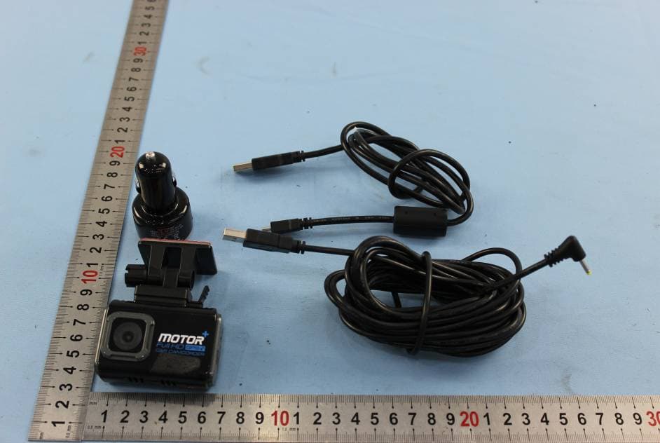
NW71041
Jun 09, 2015Dash Cam Wi-Fi IN-CAR Camera, iON Car Dash Cam with Wi-Fi
Equipment Class
DTS - Digital Transmission System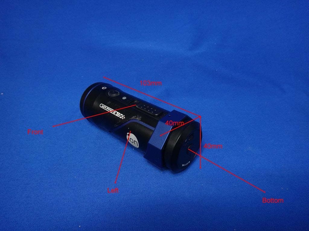
NW71022
Sep 14, 2013iON Air Pro 3 WiFi / Air Pro 3 WiFi / Gen 3 WiFi / iON Air Pro 3 Value Pack/ HD Sports Video Camera
Equipment Class
DTS - Digital Transmission System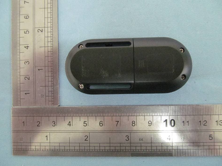
NW75005T
Nov 06, 2012Remote Controller
Equipment Class
DXX - Part 15 Low Power Communication Device Transmitter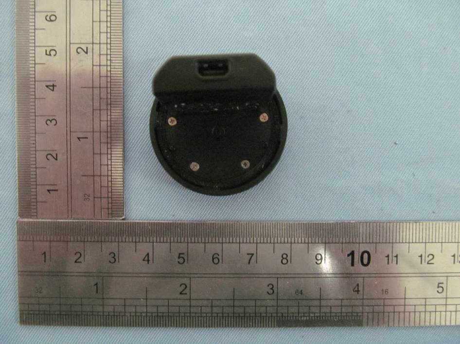
NW75005R
Nov 06, 2012Remote PODZ
Equipment Class
DXX - Part 15 Low Power Communication Device Transmitter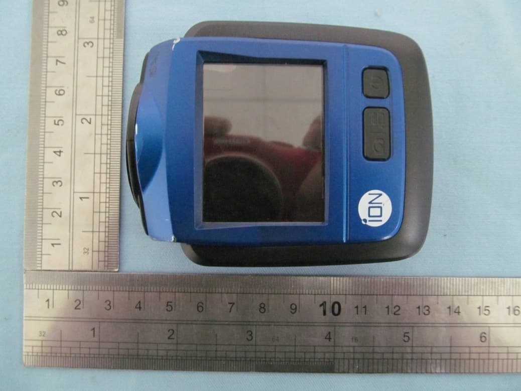
NW71007
Oct 09, 2012Wireless HD Sports Video Camera (iON The Game / Game / The Game)
Equipment Class
DTS - Digital Transmission System