NYC-GH58102.4GHz/5.8GHz Analog Cordless Phone (Base)
Belco International Co Ltd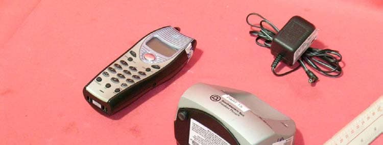
Click to zoom
Application Details
- Equipment Class
- DXT - Part 15 Low Power Transceiver, Rx Verified
- Date of Grant
- Mar 03, 2004
- Application Purpose
- Original Equipment
- Date of Application
- Mar 03, 2004
- Equipment Note
- 2.4GHz/5.8GHz Analog Cordless Phone (Base)
- Frequency Range
- 5803.01900000 - 5816.01900000
- Company
- Belco International Co Ltd
- Country
- South Korea
Documents & Files
Document Text
Text extracted from the exhibit documents filed with the FCC. Open a document above to read the original.
Block Diagram
5810BLKB.sch-1 - Wed Jan 28 11:20:57 2004
External Photos
External photos FCC ID: NYC-GH5810 External photos FCC ID: NYC-GH5810
Internal Photos
Internal photos FCC ID: NYC-GH5810 Base assembly (View 1) Base assembly (View 2) Internal photos FCC ID: NYC-GH5810 Base Main PCB comp side Base Main PCB solder side Internal photos FCC ID: NYC-GH5810 Base LED front side Base LED rear side Internal photos FCC ID: NYC-GH5810 Base Oscillator PCB comp side Base Oscillator PCB solder side
Operational Description
DESCRIPTION OF CIRCUIT OPERATION AUTOMIC DIGITAL SECURITY A special security code (up to 65,536 combinations) is automatically and randomly generated to insure privacy. 1. BASE UNIT The demodulated signal, resulting from Double Super Heterodyne system, which appears at output Pin No.3 of CON1 is sent to IC2 (COMPANDER IC) Pin No.16 for Expansion. The expended audio signal output from Pin No.19 is coupled to Q8 during the TALK mode. The audio signal is sent to the Telephone Line via Q3. The demodulated data code from CON1 Pin No.3 is fed to U5-B. It’s output is connected to Pin No.31(Data Reference Input Pin) of IC4. The Audio signal receiving from TEL-LINE is input to IC2 Pin No.8 for compression. The compressed audio signal from Pin No.1 of IC2 is connected to Pin No.10 of CON1 for Audio signal modulation. Pin No.21 of IC4 generates data codes that should be transmitted to the hand set. The data code is connected to Pin No.10 of CON1 for Data modulation. Line control is done by Pin No.10 of IC4 Ring signal monitored by U5-A is detected by Pin No.9 of IC4 and Base Unit sends Ring Data Code to hand set. DTMF dialing is generated by Pin no.38 of IC4 and this signal is sent to TEL-LINE through the Q8 and Q3. When the hand set is placed on the base cradle, the charging is detected by Pin No.8 of IC4 and IC4 sends I.D data codes to handset for security code setting. When the handset is far away from base unit, squelch circuit of IC1 in RF part operates and Pin No.13 of IC1 goes “HI”. This Squelch Detection Signal will be detected by Pin No.30 of IC4 (the micro processor) and the base set goes to Stand-By mode after 20 sec. The power of the base set is supplied by IC5(5V REGULATOR IC). IN-USE LED display is controlled by Pin No.23 of IC4. 2. HAND SET Receiver unit The demodulated signal, resulting from Double Super Heterodyne system, which appears at output Pin No.3 of CON1 is connected to Pin No.16 of U2-A(Expander input). The audio output from Pin No.19 of U2-B(Expender output) is output to the with HAC compatibility through Q8. The demodulated data code from Pin No.3 of CON1 is fed to Q10,Q9. It’s output is connected to Pin No.26(Data input Pin) of U1. Voice signal from C-MIC is coupled to Pin No.8 of U2-A. The voice signal is compressed by Compressor of U2 and Voice signal output of Pin No.1(U2-A) is connected to Pin no.10 of CON1 for Audio signal modulation. Pin No.29 of U1 generates data codes that should be transmitted to the base set. the data code is connected to Pin No.10 of CON1 for Data modulation. During the charging, Charging is detected by Pin No.23 of U1 Key board operation is monitored by Pin No.50~53,66,67 and 58~61 of U1. Key Tone Signal and the ringing Signal from Pin No.62,68 of U1 drives the BUZZER. LCD display is controlled by Pin No.1~9,70~100 of U1. Volume is controlled by Pin No.11,12 of U1 and drives the Q7,Q15 3. BASE RF MODULE 1) RX PART The Receiver front-end contains a Band Pass Filter and RF Low Noise Amplifier, a active Transistor Mixer, a Ceramic Filter and 10.73MHz IF Amplifier. Also it includes buffer Amplifier for the generation of Local Oscillator Power. This front-end Receiver receivers RF signal from the Antenna and RF signals within this Frequency range is 2468.0MHz~2479.7MHz pass through RF Low Noise Amp (Q1) and Band Pass Filter (F1). After passing through the Band Pass Filter and the RF signal is Mixed within 1’ST Local Frequency from Voltage Controlled Oscillator. The signal is amplified on the IF AMP Transistor (Q3) and the signal pass through the 10.73MHz Ceramic Filter (F3). After the IF signal pass the Ceramic Filter, the signal enter by the FM IF (Intermediate Frequency) IC (IC1). And the signal is mixed in the FM IF IC (IC1). The Output signal in the FM IF IC (IC1) streams from the AF-Output terminal of the connector 1 to the base set. FIG.3 Rx ANTENNA 2468.0~2479.7MHz IF IC F2,3 10. 73MH z IC1 KA3361 AF-OUT F1 BPF 2475MHz LNA Q1 VCO Q6 819.1~823.0MHz MIXER Q2 1’ST LOCAL FREQUENCY 2’nd LOCAL FREQ. TCXO 11.15MHz 2) TX PART The signal is made to the BASE and enter by the AF-Input terminal of the connector (PIN NO.10 of CON1). The signal send the Modulation terminal of the TX VCO and the TX Radio Frequency adjust the Trimmer Capacitor (VC1). The RF signal enter by the Transistor Power AMP (Q7) and the signal is amplified in the Q5,Q10. The RF signal enter by the Band Pass Filter, to wards the Antenna. The last Transmission RF signal is 5803.019MHz~5816.019MHz. FIG. 4 AF-IN VCO Q8 TCXO 11.15MHz TREMMER CAP. VC1 Q7,5,10 F4 BPF 5815MHz Tx ANTHNNA 5803.019~5816.019MHz IC2 PLL IC KA8825B VCO VCO FREQ. 1160.6038~1163.2038MHz 3. PORTABLE RF MODULE 1) RX RART The Receiver front-end contains a Band Pass Filter and RF Low Noise Amplifier, a active Transistor Mixer, a Ceramic Filter and 10.73MHz IF Amplifier. Also it includes buffer Amplifier for the generation of Local Oscillator Power. This front-end Receiver receivers RF signal from the Antenna and RF signals within this Frequency range is 5803.019MHz~5816.019MHz pass through RF Amp (Q1,Q10) and Band Pass Filter (F1). After passing through the Band Pass Filter and the RF signal is Mixed within 1’ST Local Frequency from Voltage Controlled Oscillator. The signal is amplified on the IF AMP Transistor (Q2,Q3) and the signal pass through the 10.7MHz Ceramic Filter (F2,F4). After the IF signal pass the Ceramic Filter, the signal enter by the FM IF (Intermediate Frequency) IC (IC2). And the signal is mixed in the FM IF IC (IC2). The Output signal in the FM IF IC (IC2) streams from the AF Output terminal of the connector 1 to the portable set. FIG.3 Rx ANTENNA 5803.019~5816.019MHz IF IC KA3361 F2,4 10.73MHz IC201 AF-OUT F1 BPF 5815MHz LNA Q1,Q10 VCO FREQUENCY 1162.7538~1165.3538MHz MIXER Q2 1’ST LOCAL FREQUENCY 2’nd LOCAL FREQ. TCXO 11.15MHz 2) TX PART The signal is made to the handy main and enter by the AF-Input terminal of the connector (PIN NO.10 of CON1). The signal send the Modulation terminal of the TX VC…
Text truncated - open the document above for the full version.
Schematics
5810B.sch-1 - Fri Dec 05 10:56:43 2003 5_8 RFBN_BC.sch-1 - Fri Dec 05 10:55:48 2003
Test Report
INTERTEK TESTING SERVICES FCC ID: NYC-GH5810 i LIST OF EXHIBITS INTRODUCTION EXHIBIT 1: General Description EXHIBIT 2: System Test Configuration EXHIBIT 3: Emission Results EXHIBIT 4: Equipment Photographs EXHIBIT 5: Product Labelling EXHIBIT 6: Technical Specifications EXHIBIT 7: Instruction Manual EXHIBIT 8: Security Code Information INTERTEK TESTING SERVICES FCC ID: NYC-GH5810 ii MEASUREMENT/TECHNICAL REPORT Belco International Co., Ltd. - MODEL: GH-5810(XXXXX) FCC ID: NYC-GH5810 This report concerns (check one:) Original Grant X Class II Change Equipment Type : Cordless Telephone (example : computer, modem, transmitter, etc.) Deferred grant requested per 47 CFR 0.457(d)(1)(ii)? Yes No X If yes, defer until : date Company Name agrees to notify the Commission by: date of the intended date of announcement of the product so that the grant can be issued on that date. Transition Rules Request per 15.37 ? Yes No X If no, assumed Part 15, Subpart C for intentional radiator - the new 47 CFR [12-08-03 Edition] Provision. Report prepared by: Tommy Leung Intertek Testing Services. 2/F., Garment Centre, 576 Castle Peak Road, Kowloon, Hong Kong. Phone : 852-2173-8538 Fax: 852-2741-1693 INTERTEK TESTING SERVICES FCC ID: NYC-GH5810 iii Table of Contents 1.0 General Description ............................................................................................2 1.1 Product Description ............................................................................................2 1.2 Related Submittal(s) Grants ...............................................................................3 1.3 Test Methodology ...............................................................................................3 1.4 Test Facility .........................................................................................................3 2.0 System Test Configuration ...................................................................................5 2.1 Justification .........................................................................................................5 2.2 EUT Exercising Software....................................................................................5 2.3 Support Equipment List and Description ...........................................................6 2.4 Measurement Uncertainty ..................................................................................7 2.5 Equipment Modification ......................................................................................7 3.0 Emission Results ...................................................................................................9 3.1 Field Strength Calculation................................................................................10 3.2 Radiated Emission Configuration Photograph - Base Unit.............................11 3.3 Radiated Emission Data - Base Unit ...............................................................12 3.4 Radiated Emission on the bandedge ...............................................................16 3.5 Line Conducted Configuration Photograph - Base Unit ..................................18 3.6 Line Conducted Emission Data - Base Unit ....................................................19 4.0 Equipment Photographs .....................................................................................22 5.0 Product Labelling .................................................................................................24 6.0 Technical Specifications .....................................................................................26 7.0 Instruction Manual ...............................................................................................28 8.0 Security Code Information ..................................................................................30 INTERTEK TESTING SERVICES FCC ID: NYC-GH5810 iv List of attached file Exhibit type File Description filename Test Report Test Report report.pdf Operation Description Technical Description descri.pdf Test Setup Photo Radiated Emission for Base config photos.doc Test Report Emission Plot emission.pdf Test Setup Photo Conducted Emission config photos.doc Test Report Conducted Emission Test Result conduct.pdf External Photo External Photo external photos.doc Internal Photo Internal Photo internal photos.doc Block Diagram Block Diagram block.pdf Schematics Circuit Diagram circuit.pdf ID Label/Location Label Artwork and Location label.pdf User Manual User Manual manual.pdf User Manual FCC Information fcc information.pdf INTERTEK TESTING SERVICES FCC ID: NYC-GH5810 1 EXHIBIT 1 GENERAL DESCRIPTION INTERTEK TESTING SERVICES FCC ID: NYC-GH5810 2 1.0 General Description 1.1 Product Description The GH-5810 is a 2.4GHz/5.8GHz 40 Channel Analog Modulation Cordless Phone with Caller ID. Base Unit and handset operate at frequency of 5803.019MHz to 5816.019MHz and 2468.000MHz to 2479.700MHz respectively. The unit is capable of either tone or pulse dialing. The internal power supply's isolation is accomplished through a power transformer having an adequate dielectric rating. The circuit wiring is consistent under the requirement of part 68. The handset unit consists of a keypad with twelve standard keys (0,...9,*,#), six function keys (CID, Del/Redial, Mem/Save, Flash/Edit, Callback, Prog/Mute), and one channel switch key. A Talk key is provided to control pick/release telephone line in a toggle base. The base unit has a page key, which is used to page the handset unit. The antennas used in base unit and handset are integral, and the tested sample is a prototype. The model: GH-5810 is one of the model: GH-5810(XXXXX). The suffix, (XXXXX), followed by the model number is represented color code in any alpha characters from A to Z. The model numbers with different suffix are identical in electrical, mechanical, and physical design. The difference in suffix of model number serves as marketing strategy. The circuit description is s…
Text truncated - open the document above for the full version.
Test Report
Report No.:03169481 Talk Mode Ctrl No.:N/A PAGE 1 Tested By:Hong, Report No.:03169481 Scan Settings (1 Range) |--------- Frequencies -----------||----------- Receiver Settings ------------| Start Stop Step IF BW Detector M-Time Atten Preamp OpRge 150k 30M 5k 10k PK+AV 10ms AUTO LN OFF 60dB Final Measurement: x QP / + AV Meas Time: 1 s Subranges: 16 Acc Margin: 20dB Transducer No. Start Stop Name 21 9k 30M EW0698 0 10 20 30 40 50 60 70 80 90 dBuV 100 0.15 MHz 30110 F15Q F15A Report No.:03169481 Talk Mode Ctrl No.:N/A Tested By:Hong, Report No.:03169481 Scan Settings (1 Range) |--------- Frequencies -----------||----------- Receiver Settings ------------| Start Stop Step IF BW Detector M-Time Atten Preamp OpRge 150k 30M 5k 10k PK+AV 10ms AUTO LN OFF 60dB Final Measurement Results: Frequency QP Level QP Limit MHz dBuV dBuV no Results Frequency AV Level AV Limit MHz dBuV dBuV 17.90000 32.0 50.0 23.00000 33.6 50.0 * limit exceeded
Test Setup Photos
The Worst Case Configuration Photographs FCC ID: NYC-GH5810 Radiated Emission – Base Front View Rear View The Worst Case Configuration Photographs FCC ID: NYC-GH5810 Conducted Emission Front View Rear View The Worst Case Configuration Photographs FCC ID: NYC-GH5810 Conducted Emission Side View
Test Setup Photos
The Worst Case Configuration Photographs FCC ID: NYC-GH5810 Radiated Emission – Base Front View Rear View The Worst Case Configuration Photographs FCC ID: NYC-GH5810 Conducted Emission Front View Rear View The Worst Case Configuration Photographs FCC ID: NYC-GH5810 Conducted Emission Side View
Contact Information
Applicant
Diana Jung(Certification Management)
Technical Contact
Intertek Testing Services Hong Kong Ltd.Tommy Leung
[email protected]852-2173-8538
2/F., Garment Centre · Kowloon · Hong Kong
Non-Technical Contact
Intertek Testing Services Hong Kong Ltd.Tommy Leung
[email protected]852-2173-8538
Test Firm
Intertek Testing Services Hong KongBilly Chow
Technical Specifications
| # | Rule Parts | Frequency Range | Power Output |
|---|---|---|---|
| 1 | 15C | 5.80 GHz - 5.82 GHz | - |
Other Applications from Belco International Co Ltd

NYC-PM2400
Mar 31, 20052.4 GHz Analog Cordless Telephone
Equipment Class
DXT - Part 15 Low Power Transceiver, Rx Verified
NYC-PM2420
Mar 28, 20052.4 GHz Analog Cordless Telephone
Equipment Class
DXT - Part 15 Low Power Transceiver, Rx Verified
NYC-PM5820H
Dec 13, 20045.8GHz/2.4GHz 40 Channel Cordless Phone (Handset)
Equipment Class
DXX - Part 15 Low Power Communication Device Transmitter
NYC-PM5820
Dec 13, 20045.8GHz/2.4GHz 40 Channel Cordless Phone (Base)
Equipment Class
DXX - Part 15 Low Power Communication Device Transmitter
NYC-GH5877
Sep 19, 20045.8GHz/2.4GHz 40 Channel Cordless Phone (Base)
Equipment Class
DXX - Part 15 Low Power Communication Device Transmitter