NYC-GH5810H2.4GHz/5.8GHz Analog Cordless Phone (Handset)
Belco International Co Ltd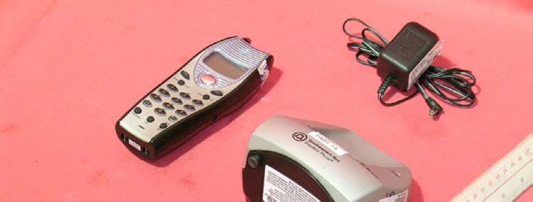
Click to zoom
Application Details
- Equipment Class
- DXT - Part 15 Low Power Transceiver, Rx Verified
- Date of Grant
- Mar 03, 2004
- Application Purpose
- Original Equipment
- Date of Application
- Mar 03, 2004
- Equipment Note
- 2.4GHz/5.8GHz Analog Cordless Phone (Handset)
- Frequency Range
- 2468.00000000 - 2479.70000000
- Company
- Belco International Co Ltd
- Country
- South Korea
Documents & Files
Document Text
Text extracted from the exhibit documents filed with the FCC. Open a document above to read the original.
Users Manual
CONSIGNES DE SÉCURITÉ IMPORTANTES Pour réduire les risques de blessure, d’incendie et d’électrocution, chaque fois que vous utilisez ce produit, appliquez les règles élémentaires de sécurité, notamment les suivantes : 1. Lisez attentivement toutes les instructions. 2. Respectez tous les avertissements et toutes les instructions apparaissant sur le produit. 3. Avant se nettoyer ce produit, débranchez la prise murale. N’utilisez pas de nettoyant liquide ni en aérosol. Pour nettoyer, utilisez simplement un chiffon humide. 4. N’utilsez jamais ce produit près d’un point d’eau (par exemple, près d’une baignoire, d’une cuvette de lavage, d’un évier de cuisine ou d’un lavabo), dans un sous-sol humide ou près d’une piscine. 5. Ne placez pas ce produit sur une table, un meuble ou un chariot instable. Si le produit tombe, il risqué d’être gravement endommagé. 6. Les fentes et les ouvertures qui se trouvent derrière ou dessous l’appareil servent à la ventilation. Pour éviter toute surchauffe, ces ouvertures ne doivent jamais être couvertes ou obstruées. Pour éviter qu’elles soient bloquées, ne placez pas le produit sur un lit, un sofa, une moquette ou une autre surface molle. Ce produit ne devrait jamais être placé près d’un radiateur ou d’un autre appareil de chauffage. 7. Ne laissez jamais d’objet posé sur le cordon d’alimentation. Ne placez pas ce produit à un endoit où le cordon risque d’être abîmé par des animaux de compagnie ou des personnes pouvant l’écraser en marchant. 8. Ne surchargez jamais les prises murales et les rallonges car vous risqueriez alors de provoquer un incendie ou une électrocution. 9. Ne faites jamais entrer des objets par les fentes du boîtier de cet appareil car vous pourriez toucher des points de tension dangereux ou causer un court-circuit pouvant entraîner un incendie ou une électrocution. Il ne faut jamais verser de liquide sur ce produit. 10. Pour réduire les risques d’électrocution, ne tentez pas de démonter ce produit. Lorsqu’une réparation semble nécessaire, apportez-le plutôt chez un technicien qualifié. Si vous ouvrez ou enlevez une pièce du boîter, vous vous exposez à des tensions électriques dangereuses et à d’autres risques. Si l’appareil est mal assemblé, une électrocution pourrait survenir lors de la prochaine utilsation. 11. Dans les situations suivantes, débranchez tous les cordons d’amlimentation et consultez un technicien qualifié. A. Lorsque le cordon d’alimentation est endommagé ou effiloché. B. Lorsqu’un liquide a été renversé sur le produit. C. Lorsque le produit a été exposé à la pluie à l’eau. D. Lorsque le produit ne fonctionne pas normalement et que toutes les instructions ont été suivies. Ne réglez les commandes décrites dans le quide d’utilsation. Un mauvais réglade des autres commandes peut causer des dommages, et l’intervention d’un technicien qualifié pourrait être nécessaire pour remettre le produit en état. 12. Évitez d’utiliser un téléphone (sauf un téléphone sans fil) durant un orage électrique. Il exists alors des risques faibles d’électrocution par un éclair. 13. S’il y a une fuite de gaz, n’avisez pas les autorités avec un téléphone situé près de la fuite. 14. Utilsez uniqement le type de pile indiqué dans votre guide d’utilsation. Ne jetez jamais des vieilles piles dans un feu. Elles risqueraient d’exploser. Vérifiez réglementation locale pour savoir comment en disposer. 15. ATTENTION- Il y a danger d’exposioin s’il y a remplacement incorrect de la batterie. Remplacer uniquement avec une batterie du même type ou d’un type équivalent recommandé par le constructeur. Mettre au rebut les batteries usagées conformément aux instructions du fabricant.
Block Diagram
5810BLKH.sch-1 - Wed Jan 28 11:21:46 2004
External Photos
External photos FCC ID: NYC-GH5810H External photos FCC ID: NYC-GH5810H
Internal Photos
Internal photos FCC ID: NYC-GH5810H Handset assembly Handset Main PCB comp side (View 1) Internal photos FCC ID: NYC-GH5810H Handset Main PCB comp side (View 2) Handset Main PCB display side Internal photos FCC ID: NYC-GH5810H Handset Oscillator PCB comp side Handset Oscillator PCB solder side
Operational Description
DESCRIPTION OF CIRCUIT OPERATION AUTOMIC DIGITAL SECURITY A special security code (up to 65,536 combinations) is automatically and randomly generated to insure privacy. 1. BASE UNIT The demodulated signal, resulting from Double Super Heterodyne system, which appears at output Pin No.3 of CON1 is sent to IC2 (COMPANDER IC) Pin No.16 for Expansion. The expended audio signal output from Pin No.19 is coupled to Q8 during the TALK mode. The audio signal is sent to the Telephone Line via Q3. The demodulated data code from CON1 Pin No.3 is fed to U5-B. It’s output is connected to Pin No.31(Data Reference Input Pin) of IC4. The Audio signal receiving from TEL-LINE is input to IC2 Pin No.8 for compression. The compressed audio signal from Pin No.1 of IC2 is connected to Pin No.10 of CON1 for Audio signal modulation. Pin No.21 of IC4 generates data codes that should be transmitted to the hand set. The data code is connected to Pin No.10 of CON1 for Data modulation. Line control is done by Pin No.10 of IC4 Ring signal monitored by U5-A is detected by Pin No.9 of IC4 and Base Unit sends Ring Data Code to hand set. DTMF dialing is generated by Pin no.38 of IC4 and this signal is sent to TEL-LINE through the Q8 and Q3. When the hand set is placed on the base cradle, the charging is detected by Pin No.8 of IC4 and IC4 sends I.D data codes to handset for security code setting. When the handset is far away from base unit, squelch circuit of IC1 in RF part operates and Pin No.13 of IC1 goes “HI”. This Squelch Detection Signal will be detected by Pin No.30 of IC4 (the micro processor) and the base set goes to Stand-By mode after 20 sec. The power of the base set is supplied by IC5(5V REGULATOR IC). IN-USE LED display is controlled by Pin No.23 of IC4. 2. HAND SET Receiver unit The demodulated signal, resulting from Double Super Heterodyne system, which appears at output Pin No.3 of CON1 is connected to Pin No.16 of U2-A(Expander input). The audio output from Pin No.19 of U2-B(Expender output) is output to the with HAC compatibility through Q8. The demodulated data code from Pin No.3 of CON1 is fed to Q10,Q9. It’s output is connected to Pin No.26(Data input Pin) of U1. Voice signal from C-MIC is coupled to Pin No.8 of U2-A. The voice signal is compressed by Compressor of U2 and Voice signal output of Pin No.1(U2-A) is connected to Pin no.10 of CON1 for Audio signal modulation. Pin No.29 of U1 generates data codes that should be transmitted to the base set. the data code is connected to Pin No.10 of CON1 for Data modulation. During the charging, Charging is detected by Pin No.23 of U1 Key board operation is monitored by Pin No.50~53,66,67 and 58~61 of U1. Key Tone Signal and the ringing Signal from Pin No.62,68 of U1 drives the BUZZER. LCD display is controlled by Pin No.1~9,70~100 of U1. Volume is controlled by Pin No.11,12 of U1 and drives the Q7,Q15 3. BASE RF MODULE 1) RX PART The Receiver front-end contains a Band Pass Filter and RF Low Noise Amplifier, a active Transistor Mixer, a Ceramic Filter and 10.73MHz IF Amplifier. Also it includes buffer Amplifier for the generation of Local Oscillator Power. This front-end Receiver receivers RF signal from the Antenna and RF signals within this Frequency range is 2468.0MHz~2479.7MHz pass through RF Low Noise Amp (Q1) and Band Pass Filter (F1). After passing through the Band Pass Filter and the RF signal is Mixed within 1’ST Local Frequency from Voltage Controlled Oscillator. The signal is amplified on the IF AMP Transistor (Q3) and the signal pass through the 10.73MHz Ceramic Filter (F3). After the IF signal pass the Ceramic Filter, the signal enter by the FM IF (Intermediate Frequency) IC (IC1). And the signal is mixed in the FM IF IC (IC1). The Output signal in the FM IF IC (IC1) streams from the AF-Output terminal of the connector 1 to the base set. FIG.3 Rx ANTENNA 2468.0~2479.7MHz IF IC F2,3 10. 73MH z IC1 KA3361 AF-OUT F1 BPF 2475MHz LNA Q1 VCO Q6 819.1~823.0MHz MIXER Q2 1’ST LOCAL FREQUENCY 2’nd LOCAL FREQ. TCXO 11.15MHz 2) TX PART The signal is made to the BASE and enter by the AF-Input terminal of the connector (PIN NO.10 of CON1). The signal send the Modulation terminal of the TX VCO and the TX Radio Frequency adjust the Trimmer Capacitor (VC1). The RF signal enter by the Transistor Power AMP (Q7) and the signal is amplified in the Q5,Q10. The RF signal enter by the Band Pass Filter, to wards the Antenna. The last Transmission RF signal is 5803.019MHz~5816.019MHz. FIG. 4 AF-IN VCO Q8 TCXO 11.15MHz TREMMER CAP. VC1 Q7,5,10 F4 BPF 5815MHz Tx ANTHNNA 5803.019~5816.019MHz IC2 PLL IC KA8825B VCO VCO FREQ. 1160.6038~1163.2038MHz 3. PORTABLE RF MODULE 1) RX RART The Receiver front-end contains a Band Pass Filter and RF Low Noise Amplifier, a active Transistor Mixer, a Ceramic Filter and 10.73MHz IF Amplifier. Also it includes buffer Amplifier for the generation of Local Oscillator Power. This front-end Receiver receivers RF signal from the Antenna and RF signals within this Frequency range is 5803.019MHz~5816.019MHz pass through RF Amp (Q1,Q10) and Band Pass Filter (F1). After passing through the Band Pass Filter and the RF signal is Mixed within 1’ST Local Frequency from Voltage Controlled Oscillator. The signal is amplified on the IF AMP Transistor (Q2,Q3) and the signal pass through the 10.7MHz Ceramic Filter (F2,F4). After the IF signal pass the Ceramic Filter, the signal enter by the FM IF (Intermediate Frequency) IC (IC2). And the signal is mixed in the FM IF IC (IC2). The Output signal in the FM IF IC (IC2) streams from the AF Output terminal of the connector 1 to the portable set. FIG.3 Rx ANTENNA 5803.019~5816.019MHz IF IC KA3361 F2,4 10.73MHz IC201 AF-OUT F1 BPF 5815MHz LNA Q1,Q10 VCO FREQUENCY 1162.7538~1165.3538MHz MIXER Q2 1’ST LOCAL FREQUENCY 2’nd LOCAL FREQ. TCXO 11.15MHz 2) TX PART The signal is made to the handy main and enter by the AF-Input terminal of the connector (PIN NO.10 of CON1). The signal send the Modulation terminal of the TX VC…
Text truncated - open the document above for the full version.
Schematics
5810H.sch-1 - Fri Dec 05 10:57:52 2003 5_8 RFHN_BC.sch-1 - Fri Dec 05 10:54:44 2003
Test Report
INTERTEK TESTING SERVICES FCC ID: NYC-GH5810H i LIST OF EXHIBITS INTRODUCTION EXHIBIT 1: General Description EXHIBIT 2: System Test Configuration EXHIBIT 3: Emission Results EXHIBIT 4: Equipment Photographs EXHIBIT 5: Product Labelling EXHIBIT 6: Technical Specifications EXHIBIT 7: Instruction Manual EXHIBIT 8: Security Code Information INTERTEK TESTING SERVICES FCC ID: NYC-GH5810H ii MEASUREMENT/TECHNICAL REPORT Belco International Co., Ltd. - MODEL: GH-5810(XXXXX) FCC ID: NYC-GH5810H This report concerns (check one:) Original Grant X Class II Change Equipment Type : Cordless Telephone (example : computer, modem, transmitter, etc.) Deferred grant requested per 47 CFR 0.457(d)(1)(ii)? Yes No X If yes, defer until : date Company Name agrees to notify the Commission by: date of the intended date of announcement of the product so that the grant can be issued on that date. Transition Rules Request per 15.37 ? Yes No X If no, assumed Part 15, Subpart C for intentional radiator - the new 47 CFR [12-08-03 Edition] Provision. Report prepared by: Tommy Leung Intertek Testing Services. 2/F., Garment Centre, 576 Castle Peak Road, Kowloon, Hong Kong. Phone : 852-2173-8538 Fax: 852-2741-1693 INTERTEK TESTING SERVICES FCC ID: NYC-GH5810H iii Table of Contents 1.0 General Description ............................................................................................2 1.1 Product Description ............................................................................................2 1.2 Related Submittal(s) Grants ...............................................................................3 1.3 Test Methodology ...............................................................................................3 1.4 Test Facility .........................................................................................................3 2.0 System Test Configuration ...................................................................................5 2.1 Justification .........................................................................................................5 2.2 EUT Exercising Software....................................................................................5 2.3 Support Equipment List and Description ...........................................................6 2.4 Measurement Uncertainty ..................................................................................7 2.5 Equipment Modification ......................................................................................7 3.0 Emission Results ...................................................................................................9 3.1 Field Strength Calculation................................................................................10 3.2 Radiated Emission Configuration Photograph - Handset ...............................11 3.3 Radiated Emission Data - Handset .................................................................12 3.4 Radiated Emission on the bandedge ..............................................................16 4.0 Equipment Photographs .....................................................................................19 5.0 Product Labelling .................................................................................................21 6.0 Technical Specifications .....................................................................................23 7.0 Instruction Manual ...............................................................................................25 8.0 Security Code Information ..................................................................................27 INTERTEK TESTING SERVICES FCC ID: NYC-GH5810H iv List of attached file Exhibit type File Description filename Test Report Test Report report.pdf Operation Description Technical Description descri.pdf Test Setup Photo Radiated Emission for Base config photos.doc Test Report Emission Plot emission.pdf External Photo External Photo external photos.doc Internal Photo Internal Photo internal photos.doc Block Diagram Block Diagram block.pdf Schematics Circuit Diagram circuit.pdf ID Label/Location Label Artwork and Location label.pdf User Manual User Manual manual.pdf User Manual FCC Information fcc information.pdf INTERTEK TESTING SERVICES FCC ID: NYC-GH5810H 1 EXHIBIT 1 GENERAL DESCRIPTION INTERTEK TESTING SERVICES FCC ID: NYC-GH5810H 2 1.0 General Description 1.1 Product Description The GH-5810 is a 2.4GHz/5.8GHz 40 Channel Analog Modulation Cordless Phone with Caller ID. Base Unit and handset operate at frequency of 5803.019MHz to 5816.019MHz and 2468.000MHz to 2479.700MHz respectively. The unit is capable of either tone or pulse dialing. The internal power supply's isolation is accomplished through a power transformer having an adequate dielectric rating. The circuit wiring is consistent under the requirement of part 68. The handset unit consists of a keypad with twelve standard keys (0,...9,*,#), six function keys (CID, Del/Redial, Mem/Save, Flash/Edit, Callback, Prog/Mute), and one channel switch key. A Talk key is provided to control pick/release telephone line in a toggle base. The base unit has a page key, which is used to page the handset unit. The antennas used in base unit and handset are integral, and the tested sample is a prototype. The model: GH-5810 is one of the model: GH-5810(XXXXX). The suffix, (XXXXX), followed by the model number is represented color code in any alpha characters from A to Z. The model numbers with different suffix are identical in electrical, mechanical, and physical design. The difference in suffix of model number serves as marketing strategy. The circuit description is saved with filename: descri.pdf Connection between the device and the telephone network is accomplished through the use of USOC RJ11C in the 2-wire loop calling central office line. INTERTEK TESTING SERVICES FCC ID: NYC-GH5810H 3 1.2 Related Submittal(s) Grants This is a single application for C…
Text truncated - open the document above for the full version.
Test Setup Photos
The Worst Case Configuration Photographs FCC ID: NYC-GH5810H Radiated Emission – Handset Front View Rear View
Contact Information
Applicant
Diana Jung(Certification Management)
Technical Contact
Intertek Testing Services Hong Kong Ltd.Tommy Leung
[email protected]852-2173-8538
2/F., Garment Centre · Kowloon · Hong Kong
Non-Technical Contact
Intertek Testing Services Hong Kong Ltd.Tommy Leung
[email protected]852-2173-8538
Test Firm
Intertek Testing Services Hong KongBilly Chow
Technical Specifications
| # | Rule Parts | Frequency Range | Power Output |
|---|---|---|---|
| 1 | 15C | 2.47 GHz - 2.48 GHz | - |
Other Applications from Belco International Co Ltd

NYC-PM2400
Mar 31, 20052.4 GHz Analog Cordless Telephone
Equipment Class
DXT - Part 15 Low Power Transceiver, Rx Verified
NYC-PM2420
Mar 28, 20052.4 GHz Analog Cordless Telephone
Equipment Class
DXT - Part 15 Low Power Transceiver, Rx Verified
NYC-PM5820H
Dec 13, 20045.8GHz/2.4GHz 40 Channel Cordless Phone (Handset)
Equipment Class
DXX - Part 15 Low Power Communication Device Transmitter
NYC-PM5820
Dec 13, 20045.8GHz/2.4GHz 40 Channel Cordless Phone (Base)
Equipment Class
DXX - Part 15 Low Power Communication Device Transmitter
NYC-GH5877
Sep 19, 20045.8GHz/2.4GHz 40 Channel Cordless Phone (Base)
Equipment Class
DXX - Part 15 Low Power Communication Device Transmitter