NYCIBM-3345Cordless Headset Telephone System
Belco International Co Ltd
Click to zoom
Application Details
- Equipment Class
- DXT - Part 15 Low Power Transceiver, Rx Verified
- Date of Grant
- Apr 05, 2001
- Application Purpose
- Original Equipment
- Date of Application
- Mar 29, 2001
- Equipment Note
- Cordless Headset Telephone System
- Frequency Range
- 2474.00000000 - 2475.95000000
- Company
- Belco International Co Ltd
- Country
- South Korea
Documents & Files
Document Text
Text extracted from the exhibit documents filed with the FCC. Open a document above to read the original.
Users Manual
March 15, 2001 IBM-3345 (REV : 0.1) 1 MODEL IBM-3345 2.4GHz 40 CHANNEL CORDLESS HEADSET TELEPHONE WITH CALL WAITING CALLER ID INSTALLATION AND OPERATION GUIDE Please read this manual carefully prior to installing your telephone. March 15, 2001 IBM-3345 (REV : 0.1) 2 CONTENTS Important Safety Instructions .......................................................................................3 Battery Cautionary Instructions.....................................................................................4 Features.............................................................................................................................5~6 Introduction.......................................................................................................................7 Control Location...............................................................................................................8~10 Installation..........................................................................................................................11 Selecting a Location....................................................................................................11 Getting Started.............................................................................................................11 Connecting the Telephone.........................................................................................11~12 Installing the Battery Pack...........................................................................................13 Connecting the Headset.............................................................................................14 Operation...........................................................................................................................15 Charging the Battery Pack..........................................................................................15~16 Adjusting the Headset.................................................................................................16~17 Setting the Area Code ...............................................................................................17 Setting the Tone/Pulse Switch....................................................................................18 Using the Belt Clip.......................................................................................................18 Making Calls.................................................................................................................18 Using the Call Timer....................................................................................................18 Receiving Calls.............................................................................................................18~19 Changing Channels....................................................................................................19 Setting the Volume......................................................................................................19 Setting the Ringer Hi/Lo Switch..................................................................................19 Using the Redial/Pause Button...................................................................................19 Using the Mute Button................................................................................................19 Using the Flash button................................................................................................20 Using Tone Services on a Pulse Line.........................................................................20 Storing a Number in Memory......................................................................................20 Entering a Pause in a Stored number........................................................................20 Dialing a Stored number.............................................................................................20 Using the Call Waiting Features.................................................................................21 Receiving Caller ID Information..................................................................................21 Reviewing Caller ID Information..................................................................................22 Using the Callback feature..........................................................................................23 Unknown Calls.............................................................................................................24 Care and Maintenance................................................................................................................25 Replacing the Battery Pack........................................................................................25 Troubleshooting...........................................................................................................26 FCC Requirements.......................................................................................................................27 Warranty Information...................................................................................................................28 March 15, 2001 IBM-3345 (REV : 0.1) 3 IMPORTANT SAFETY INSTRUCTIONS When using your telephone equipment, basic safety precautions should always be followed to reduce the risk of fire, electrical shock, and injury to persons including the following: 1. Read and understand all instructions. 2. Follow all warnings and instructions marked on the product. 3. Unplug this product from the wall outlet before cleaning. Do not use liquid cleaners, or aerosol cleaners. Use a damp cloth for cleaning. If necessary, use a mild soap. 4. Do not use this product near water, for example near a bath tub, wash bowl, kitchen sink, or laundry tub, in a wet basement, or near a swimming pool. 5. Do not place this product on an unstable cart, stand or table. The product may fall, causing serious damage to the product.…
Text truncated - open the document above for the full version.
Attestation Statements
BELCO INTERNATIONAL CO., LTD. 1001-11 DOKSAN 1-DONG, KUMCHEON-KU, SEOUL 153-011, KOREA TEL : +82-2-806-9513 FAX : +82-2-894-6484 E-mail : [email protected] Date : March 29, 2001 STATEMENT OF SECURITY CODE NYCIBM-3345 FCC ID : NYCIBM-3345 Cordless telephone shall incorporate circuitry which makes use of a digital security code to provide protection against unintentional access to the public switched telephone network by the base unit and unintentional ringing by the handset (FCC Part 15.214(d)). There must be provision for at least 256 possible discrete digital (FCC Part 15.214(d)). Manufacturers must use one of the following approaches for facilitating variation in the geographic distribution of individual security codes (FCC Part 15.214(d)(2)). Provide a fixed code that is continuously varied among at least 256 discrete digital codes as each telephone is manufactured. (FCC Part 15.214(d)(2)(ii)). - We provide a fixed code that is continuously varied among 1,048,576 discrete digital codes as each telephone is manufactured. E-mail : [email protected]
External Photos
EXTERNAL FRONT SIDE FCC ID :NYCIBM- 3345 EXTERNAL BOTTOM SIDE FCCID : NYCIBM-3345 EXTERNAL BOTTOM SIDE FCC ID : NYCIBM-3345
External Photos
EXTERNAL TOP SIDE FCC ID :NYCIBM- 3345 EXTERNALBOTTOM SIDE - 1 FCC ID: NYCIBM-3345 EXTERNAL BOTTOM SIDE - 2 FCC ID : NYCIBM-3345 EXTERNALBOTTOM SIDE - 3 FCC ID : NYCIBM-3345
ID Label/Location Info
PROPOSED FCC ID. LABEL AND MARKING BASE BOTTOM SIDE
ID Label/Location Info
PROPOSED FCC ID. LABEL AND MARKING REMOTE BOTTOM SIDE BATTERY CAUTION LABEL
Internal Photos
INTERNAL TOP SIDE FCC ID : NYCIBM-3345 INTERNAL BOTTOMSIDE FCC ID : NYCIBM-3345 INTERNAL RF TOP SIDE FCC ID : NYCIBM-3345
Internal Photos
INTERNAL TOP SIDE INTERNAL BOTTOM SIDE INTERNAL RF TOP SIDE INTERNAL RF BOTTOM SIDE
Internal Photos
INTERNAL TOP SIDE INTERNAL BOTTOM SIDE INTERNAL RF TOP SIDE INTERNAL RF BOTTOM SIDE
Operational Description
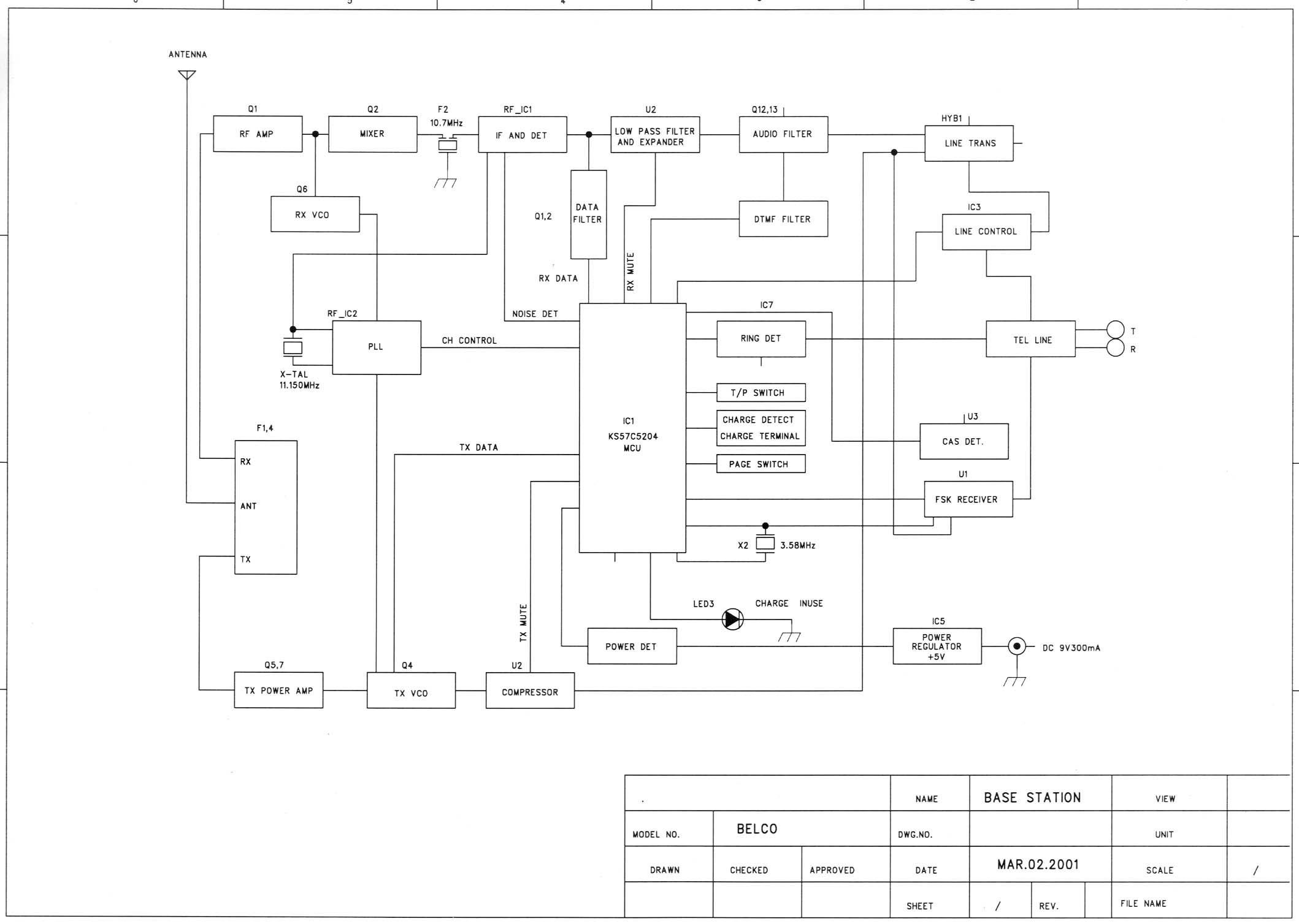
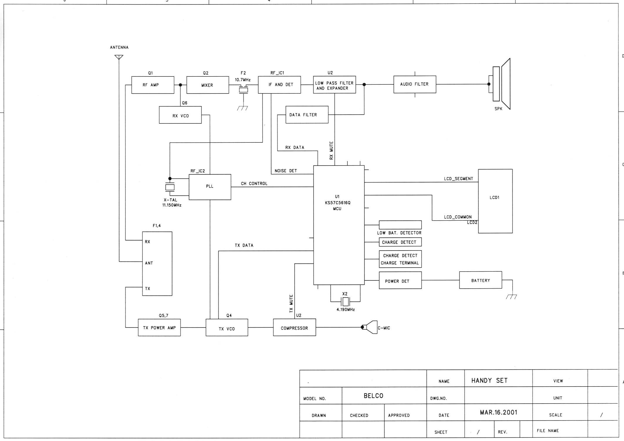
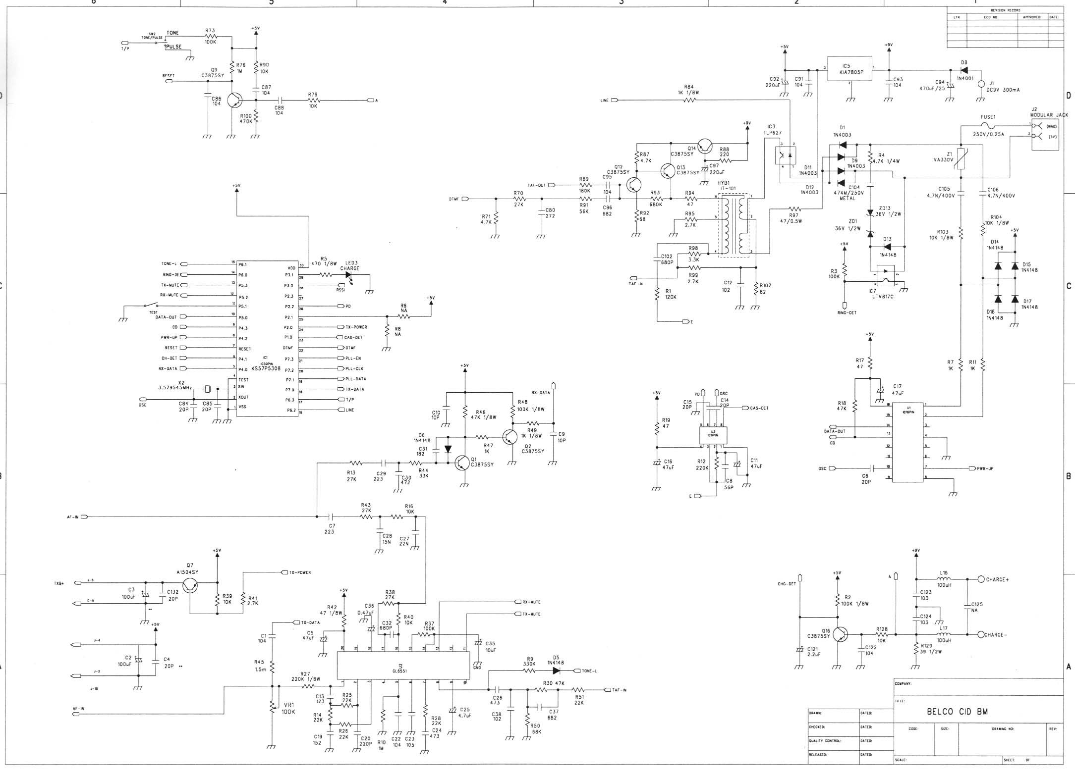
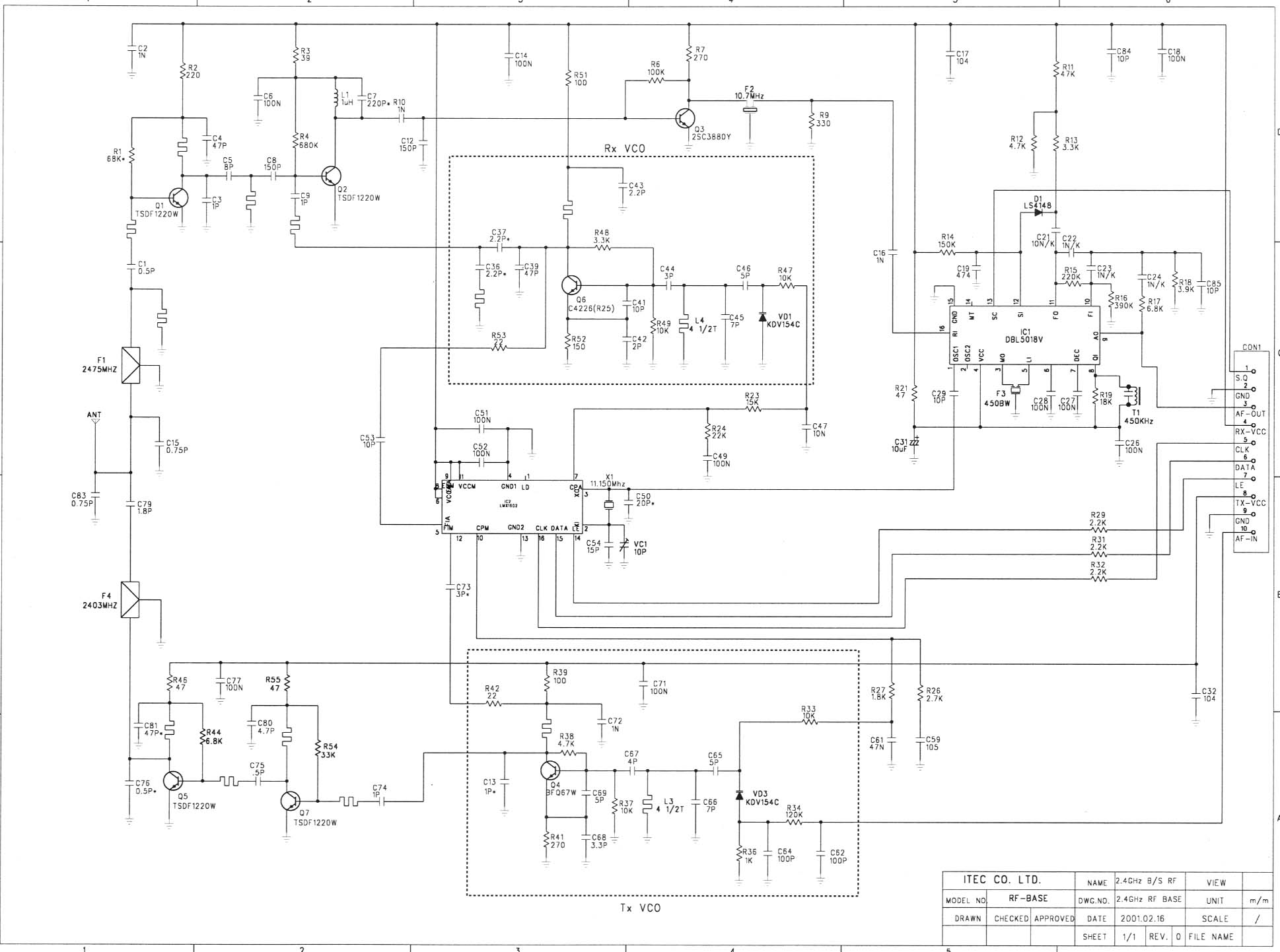
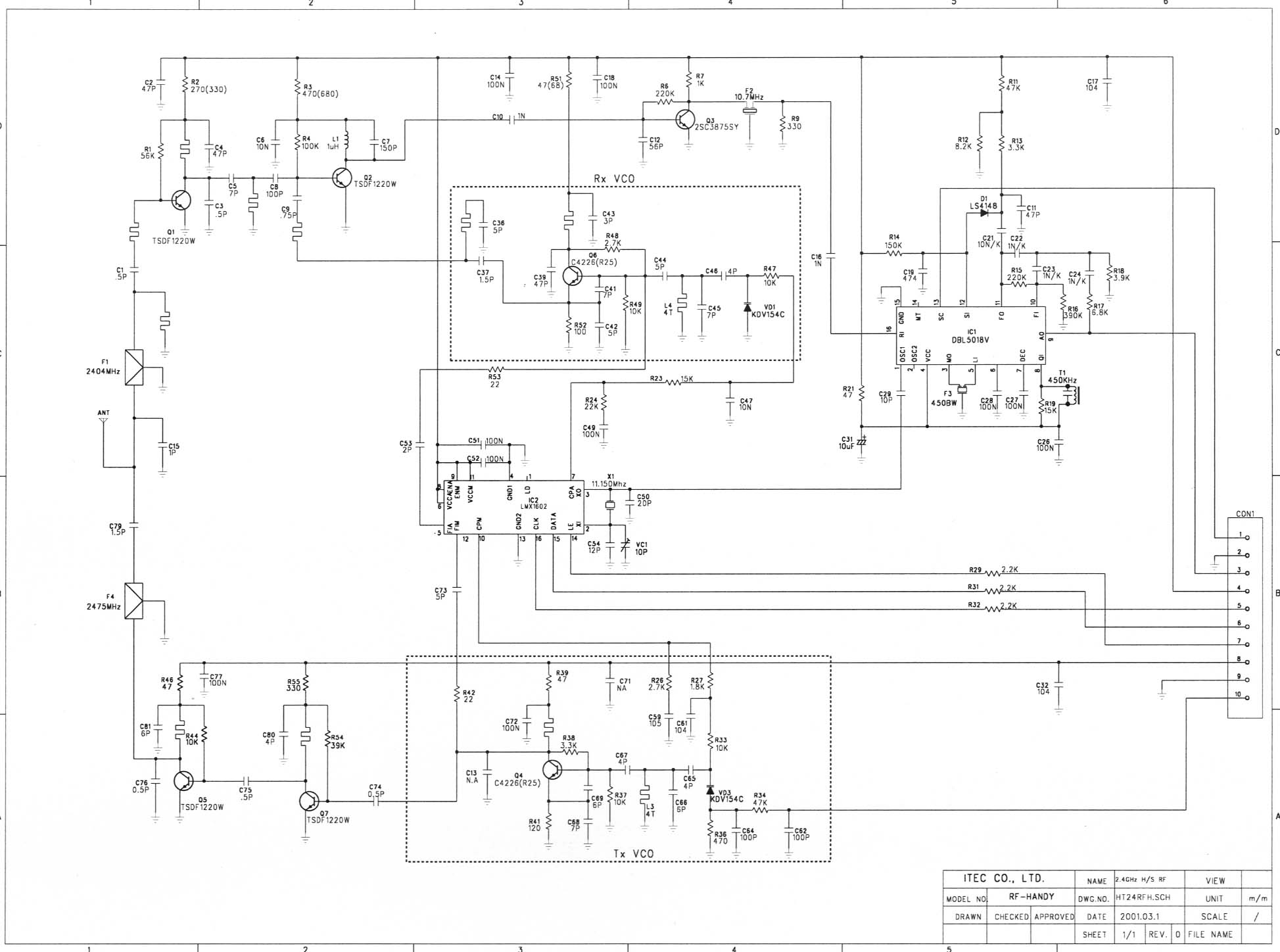
DESCRIPTION OF CIRCUIT OPERATION BASE UNIT : The demodulated signal, resulting from Double Super Heterodyne system, which appears at output Pin no.3 of J 3 is sent to U2 (COMPANDER IC) Pin no.16 for Expansion. The expended audio signal output from Pin no.19 is coupled to Q12,13 during the TEL. mode The audio signal is sent to the Telephone Line via hybrid Transformer HBY1. The demodulated data code from J3 Pin no.3 is Generated by Q1,2. It’s output is connected to CODE Input Pin no.5 of IC1 The Audio signal receiving from TEL-LINE is input to U2 Pin no.8 for compression. The compressed audio signal from Pin no.1 of U2 is connected to Pin no.10 of J3 for TX modulation. Pin no.18 of IC1 is the output port for data codes that should be transmitted to the handset the data code is connected to Pin no.10 of J3 for modulation. Line controlling is done by Pin no.16 of IC1. Ring signal monitored by IC7 (PHOTO COUPLER IC) is detected by Pin no.14 of IC1 resulting a data code to the handset. DTMF dialing is generated by IC1 Pin no.22 this signal output through the HYB1. When the handset is placed on the base cradle, the charging is detected by Pin no.6 of IC1 and IC1 sends data codes to handset for security code setting. When the handset is far away form base unit, squelch circuit of IC1 operates and Pin no.13 of IC1 goes “HI”. This will be detected by the micro processor and after 20 sec. go to Stand by mode. The power to the base unit is supplied by IC5(5V REGULATOR IC). LED display control Pin no.29 of IC1. HAND SET : The demodulated signal, resulting from Double Super Heterodyne system, which appears at output Pin no.3 of CON1 is connected to U2 Pin no.16 Expander input. The audio output from U2 Pin no.19 is finally amplified by Q1 and A.C coupled to the Receiver unit with HAC compatibility. The demodulated data code from CON1 Pin no.3 is fed to Q2,4. Q4 is connected to (DATA IN) Pin no.24 of U1. Voice signal from C-MIC is coupled to Pin no.8 of U2. The voice signal is compressed by U2 and output Pin no.1 is connected to Pin no.10 of CON1 for modulation. Pin no.33 of U1 is the output port for data code that should be transmitted to the base unit. This data code is connected to the Pin no.10 of CON1 for modulation. During the charging, it is detected by U1 Pin no.26. Key board operation is monitored by Pin no.50~ 61of U1. Key Tone and the ringing from Pin no.63 of U1 drives the BUZZER. 1. BASE RF MODULE 1) RX PART THE RECEIVER FRONT-END CONTAINS A BAND PASS FILTER, AND RF LOW NOISE AMPLIFIER, A ACTIVE TRANSISTOR MIXER, A CERAMIC FILTER AND 10. 7MHz IF AMPLIFIER. ALSO IT INCLUDES BUFFER AMPLIFIERS FOR THE GENERATION OF LOCAL OSCILLATOR POWER. THIS FRONT-END RECEIVER RECEIVERS AND RF SIGNAL FROM THE ANTENNA. AND RF SIGNALS WITHIN THIS FREQUENCY RANGE IS 2402.55MHz ~ 2475.95MHz PASS THROUGH RF AMP (Q1) AND BAND PASS FITER. AFTER PASSING THROUGH THE BAND PASS FILTER AND THE SIGNAL IS MIXED WITHIN 1’ST LOCAL FREQUENCY FROM VOLTAGE CONTROLLED OSCILLATOR. THE SIGNAL IS AMPLIFIED ON THE OF AMP TRANSISTOR (Q3) AND THE SIGNAL PASS THROUGH THE CERAMIC FILTER (10.7MHz). AFTER THE IF SIGNAL PASS THE CERAMIC FILTER, THE SIGNAL ENTER BY THE FM IF(INTERMEDIATE FREQUENCY) IC1. AND THE SIGNAL IS MIXED IN THE FM IF IC (DBL5018V). THE SIGNAL PASS THROUGH THE CERAMIC FILTER (450KHz). THE OUTPUT SIGNAL IN THE FM IF IC STREAMS FROM THE AF-OUT TERMINAL OF THE CONNECTOR TO THE BASE. FIG. 1 ANTENNA IC 1AF-OUT BPF F1 LNA Q1VCOMIXER 1’ST LOCAL FREQUENCY F2 10.7MHz IF IC DBL5018 GND 450KHz 2’ nd LOCAL FREQ. TCXO 11.15MHz 2) TX PART THE SIGNAL IS MADE TO THE BASE, ENTER BY THE AF-IN TERMINAL OF THE CONNECTOR(CON1 OF PIN NO.10). THE SIGNAL SEND THE MOD TERMINAL OF THE TX VCO. THE SIGNAL IS MIXED IN THE TX VCO MIXING THE RF SIGNAL, THE RF SIGNAL ADJUST THE TRIMMER CAPACITOR (VC1). THE RF SIGNAL ENTER BY THE TRANSMISSION POWER AMP TRANSISTOR Q5 THE SINAL IS AMPLITUDE IN THE Q7. ENTER BY THE BAND PASS FILTER. THE RF SIGNAL PASS THROUGH THE BAND PASS FILTER, TO WARDS THE ANT. THE LAST TRANSMISSION RF SIGNAL IS 2402.55MHz ~ 2475.95MHz. FIG. 2 RF MODULE AF-IN VCO BPF3 2403MHz ANTENNA PLL IC IC2 Q5,7 TCXO 11.15MHz TREMMER CAP. VC1 2. PORTABLE RF MODULE 1) RX RART THE RECEIVER FRONT-END CONTAINS A BAND PASS FILTER,AND RF LOW NOISE AMPLIFIER, ACTIVE TRANSISTOR MIXER, CERAMIC FILTER AND 10.7MHz “IF” AMPLIFTER. ALSO IT INCLUDES BUFFER AMPLIFIERS OR THE GENERATION OF LOCAL OSCILLATOR POWER. THIS FRONT-END RECEIVERS AND RF SIGNAL FROM THE ANTENNA. AND RF SIGNALS WITHIN THIS FREQUENCY RANGE IS 2403.05MHz ~ 2475.95MHz PASS THROUGH RF AMP (Q1) AND BAND PASS FILTER.. AFTER PASSING THROUGH THE BAND PASS FILTER, THE SIGNAL IS MIXED WITHIN 1’ST LOCAL FREQUENCY FROM VOLTAGE CONTROLLED OSCILLATOR. THE SIGNAL IS AMPLIFIED ON THE IF AMP TRANSISTOR (Q3) AND THE SIGNAL PASS THROUGH THE CERANIC FILTER (10.7MHz) AFTER THE IF SIGNAL PASS THE MCF FILTER, THE SIGNAL ENTER BY THE FM IF (INTERMEDIATE FREQUENCY) IC. AND THE SIGNAL IS MIXED IN THE FM IF IC (DBL5018V). THE SIGNAL PASS THROUGH THE CERAMIC FILTER (450KHz). THE OUTPUT SIGNAL IN THE FM IF IC STREAMS FROM THE AF-OUT TERMINAL OF THE CONNECTOR 1 TO THE PORTABLE. FIG.3 ANTENNA IF IC DBL5018 F1 10. 7MHz IC 1AF-OUT BPF F1 LNA Q1VCOMIXER 1’ST LOCAL FREQUENCY 450KHz2’nd LOCAL FREQ. TCXO 11.15MHz 2) TX PART THE SIGNAL IS MADE TO THE PORTABLE, ENTER BY THE AF-IN TERMINAL OF THE CONNECTOR. THE SIGNAL SEND THE MOD TERMINAL OF THE TX VCO. THE SIGNAL IS MIXED IN THE TX VCO MIXING THE RF SIGNAL, THE RF SIGNAL ADJUST THE TRIMMER CAPACITOR VC1. THE RF SIGNAL ENTER BY THE TRANSMISSION POWER AMP TRANSISTOR (Q5,7). ENTER BY THE BAND PASS FILTER. THE RF SIGNAL PASS THROUGH THE BAND PASS FILTER, TO WARDS THE ANT. THE LAST TRANSMISSION RF SIGNAL IS 2403.025MHz ~ 2475.95MHz. FIG. 4 RF MODULE AF-IN VCO TCXO 11.15MHz TREMMER CAP. VC1 Q5,7 F4 2475MHz ANTHNNA PLL IC IC2
Test Report
KTL Korea Testing Laboratory Page 1 of 16 TEST REPORT This test report only responds to the tested sample and shall not be reproduced except in full without written approval of the Korea Testing Laboratory. Tested and reported by Reviewed by Jeong-Min Kim , Senior Engineer Won-Seo Cho , EMC Team Leader KOREA TESTING LABORATORY FG101-01-02-00 222-13, Guro-Dong Guro-Gu Seoul Korea 152-053 http://www.ktl.re.kr Ref. Report No. 01-341-016-1 Name and address of the applicant Belco International Co., Ltd. 1001-11, Doksan 1-dong, Kumcheon-ku, Seoul, Korea 153-011 Standard / Test regulation FCC Part 15, Subpart C Test result Pass Incoming date : March 16, 2001 Test item(s) ; Cordless Headset Telephone System (Transmitter Portion of Base) Model/type ref. ; IBM-3345 Manufacturer ; Belco International Co., Ltd. Additional information ; -Required Authorization :Certification -FCC ID. : NYCIBM-3345 Test date : March 28, 2001 Issue date : March 30, 2001 Ref. Report No. 01 - 341 – 016-1 Page 2 of 16 TABLE OF CONTENTS I. GENERAL INFORMATION .........................................................................................................3 1. Grantee Name and Mailing Address 2. Manufacturer's Name and Mailing Address 3. Equipment Descriptions 4. Rules and Regulations 5. Measuring Procedure 6. Place of Measurement 7. Date of Measurement •±. GENERAL REQUIREMENTS OF THE EUT ..............................................................4 1. Labelling Requirement (Section 15.19 and Section 15.214) 2. Information to User (Sections 15.21) 3. Special Accessories (Section 15.27) 4. Digital Security Code (Section 15.214) •≤. CONDUCTED EMISSION MEASUREMENT (Section 15.207)............................................................ 5 - 8 1. Test Procedure 2. Photograph for the worst case configuration 3. Sample Calculation 4. Measurement Data •≥. RADIATED EMISSION MEASUREMENT (Section 15.249) .......................................................9 -14 1. Test Procedure 2. Photograph for the worst case configuration 3. Sample Calculation 4. Measurement Data •¥. OCCUPIED BANDWITH MEASUREMENT (Section 15.249).....................................................15 •μ. TEST EQUIPMENTS USED FOR FCC COMPLIANCE TESTING ....................................16 Ref. Report No. 01 - 341 – 016-1 Page 3 of 16 •∞. GENERAL INFORMATION 1. Grantee Name and : Belco International Co., Ltd. Mailing Address 1001-11, Doksan 1-dong, Kumcheon-ku, Seoul Korea 153-011 2. Manufacturer's Name and : Belco International Co., Ltd Mailing Address 1001-11, Doksan 1-dong, Kumcheon-ku, Seoul Korea 153-011 3. Equipment Descriptions 3.1 Operating Frequency : 2402.55 MHz ~ 2404.50 MHz (40 Channel 50 kHz Spacing) 3.2 Type of Emission : Frequency Modulation 3.3 Power Supply : DC 9V (AC Adapter) 4. Rules and Regulations : FCC Part 15, Subpart C 5. Measuring Procedure : ANSI C63.4-1992 6. Place of Measurement : Absorber-lined room(3-Meter) of KTL 7. Date of Measurement 7.1 Conducted Emission : March 27, 2001 7.2 Radiated Emission : March 28, 2001 Ref. Report No. 01 - 341 – 016-1 Page 4 of 16 •±. GENERAL REQUIREMENTS OF THE EUT 1. Labelling Requirement (Section 15.19 and Section 15.214) This device complies with Part 15 of the FCC Rules. Operation is subject to following two condition : (1) this device may not cause harmful interference, and (2) this device must accept any interference received, including interference that may cause undesired operation. 1.1 Location on Label : Bottom side of EUT 1.2 How Applied : By Ink-printing on Adhesive Label 2. Information to User (Section 15.21) The following or similar statements were provided in the manual for user instruction. Please refer page 4 of the attached manual for details. CAUTION : Any changes or modifications in construction of this device which are not expressly approved by the party responsible for compliance could void the user's authority to operate the equipment. 3. Special Accessories (Section 15.27) 3.1 Were the special Accessories provided? [ ] yes, [ x ] no 3.2 If yes, details for the special accessories are as follows : 3.3 If yes, were the appropriate instructions provided on the first page of the text concerned with the device? [ ] yes, [ ] no 3.4 Are these accessories provided of the type which can be readily obtained from multiple retail outlets ? [ ] yes, [ ] no And therefore does the manual specify what additional components or accessories are required to used in order to comply with the Rules? [ ] yes, [ ] no 4. Digital Security Code (Section 15.214) Was a circuitry for digital security code provided in the cordless telephone system ? [ x ] yes, [ ] no Privacy of communication may not be ensured when using this phone. Ref. Report No. 01 - 341 – 016-1 Page 5 of 16 •≤. CONDUCTED EMISSION MEASUREMENT (Section 15.207) 1. Test Procedure The base station(EUT) is designed to transmit on one of 40 channels in the band 2402.55 to 2404.50 MHz. Therefore measurements were performed with the equipment operating on three frequencies, which were the top(CH40), middle(CH20), and bottom(CH1) in the band, as per Section 15.31(m). Conducted emission measurements on the EUT were performed by "AC Power Line Conducted Emissions Testing" procedure as per ANSI C63.4. The EUT was set up on a wooden table 0.8 meters height, 1.0 by 1.5 meters in size, placed in the shielded enclosed with a side of wall of which constituted a vertical conducting surface of 2.2 m X 3.1 m in size to maintain 40 cm from the rear of EUT 2 LISN (Line Impedance Stabilization Network, EMCO, 3825/2, 50 ohm/50 uH) was installed and electrically boned to the conducting ground plane. The EUT was connected to the LISN. One of two 50ohm output terminals of the LISN was connected to the Spectrum Analyzer(HP, 8566B, 10 kHz to 22 GHz) with the Quasi-Peak Adapter (HP, 85650A, 10 kHz to 1.0 GHz) and the other was terminated in 50 ohms. Measurements were again performed after interchanging such a connection oppositely. The frequency range from …
Text truncated - open the document above for the full version.
Test Report
KTL Korea Testing Laboratory Page 1 of 12 TEST REPORT This test report only responds to the tested sample and shall not be reproduced except in full without written approval of the Korea Testing Laboratory. Tested and reported by Reviewed by Jeong-Min Kim , Senior Engineer Won-Seo Cho , EMC Team Leader KOREA TESTING LABORATORY FG101-01-02-00 222-13, Guro-Dong Guro-Gu Seoul Korea 152-053 http://www.ktl.re.kr Ref. Report No. 01-341-016-2 Name and address of the applicant Belco International Co., Ltd. 1001-11, Doksan 1-dong, Kumcheon-ku, Seoul, Korea 153-011 Standard / Test regulation FCC Part 15, Subpart C Test result Pass Incoming date : March 16, 2001 Test item(s) ; Cordless Headset Telephone System (Transmitter Portion of Headset) Model/type ref. ; IBM-3345 Manufacturer ; Belco International Co., Ltd. Additional information ; -Required Authorization :Certification -FCC ID. : NYCIBM-3345 Test date : March 28, 2001 Issue date : March 30, 2001 Ref. Report No. 01 - 341 – 016-2 Page 2 of 12 TABLE OF CONTENTS I. GENERAL INFORMATION .........................................................................................................3 1. Grantee Name and Mailing Address 2. Manufacturer's Name and Mailing Address 3. Equipment Descriptions 4. Rules and Regulations 5. Measuring Procedure 6. Place of Measurement 7. Date of Measurement •±. GENERAL REQUIREMENTS OF THE EUT ..............................................................4 1. Labelling Requirement (Section 15.19 and Section 15.214) 2. Information to User (Sections 15.21) 3. Special Accessories (Section 15.27) 4. Digital Security Code (Section 15.214) •≤. RADIATED EMISSION MEASUREMENT (Section 15.249) .......................................................5 -10 1. Test Procedure 2. Photograph for the worst case configuration 3. Sample Calculation 4. Measurement Data •≥. OCCUPIED BANDWITH MEASUREMENT (Section 15.249).....................................................11 •¥. TEST EQUIPMENTS USED FOR . FCC COMPLIANCE TESTING ....................................12 Ref. Report No. 01 - 341 – 016-2 Page 3 of 12 •∞. GENERAL INFORMATION 1. Grantee Name and : Belco International Co., Ltd. Mailing Address 1001-11, Doksan 1-dong, Kumcheon-ku, Seoul Korea 153-011 2. Manufacturer's Name and : Belco International Co., Ltd Mailing Address 1001-11, Doksan 1-dong, Kumcheon-ku, Seoul Korea 153-011 3. Equipment Descriptions 3.1 Operating Frequency : 2474.00 MHz ~ 2474.95 MHz (40 Channel 50 kHz Spacing) 3.2 Type of Emission : Frequency Modulation 3.3 Power Supply : DC 3.6V (Rechargeable Battery) 4. Rules and Regulations : FCC Part 15, Subpart C 5. Measuring Procedure : ANSI C63.4-1992 6. Place of Measurement : Absorber-lined room(3-Meter) of KTL 7. Date of Measurement 7.1 Conducted Emission : Not Applicable 7.2 Radiated Emission : March 28, 2001 Ref. Report No. 01 - 341 – 016-2 Page 4 of 12 •±. GENERAL REQUIREMENTS OF THE EUT 1. Labelling Requirement (Section 15.19 and Section 15.214) This device complies with Part 15 of the FCC Rules. Operation is subject to following two condition : (1)this device may not cause harmful interference, and (2) this device must accept any interference received, including interference that may cause undesired operation. 1.1 Location on Enclosure : Manual for Installation and Operating Instruction 1.2 How Applied : Printing 2. Information to User (Section 15.21) The following or similar statements were provided in the manual for user instruction. Please refer page 4 of the attached manual for details. CAUTION : Any changes or modifications in construction of this device which are not expressly approved by the party responsible for compliance could void the user's authority to operate the equipment. 3. Special Accessories (Section 15.27) 3.1 Were the special Accessories provided? [ ] yes, [ x ] no 3.2 If yes, details for the special accessories are as follows : 3.3 If yes, were the appropriate instructions provided on the first page of the text concerned with the device? [ ] yes, [ ] no 3.4 Are these accessories provided of the type which can be readily obtained from multiple retail outlets ? [ ] yes, [ ] no And therefore does the manual specify what additional components or accessories are required to used in order to comply with the Rules? [ ] yes, [ ] no 4. Digital Security Code (Section 15.214) Was a circuitry for digital security code provided in the cordless telephone system ? [ x ] yes, [ ] no Privacy of communication may not be ensured when using this phone. Ref. Report No. 01 - 341 – 016-2 Page 5 of 12 •≤. RADIATED EMISSION MEASUREMENT (Section 15.249) 1. Test Procedure 1.1 Preliminary Testing for Reference The headset(EUT) is designed to transmit on one of 40 channels in the band 2474.00 to 2475.95 MHz. Therefore measurements were performed with the equipment operating on three frequencies, which were the top(CH40), middle(CH20), and bottom(CH1) in the band, as per Section 15.31(m). Preliminary testing was performed in a KTL absorber-lined room to determine the emission characteristics of the EUT. The EUT was placed on the wooden table which has dimensions of 0.8 meters in height, 1 meter in length and 1.5 meters in width. Receiving antenna(Biconical antenna : 30 to 300 MHz, Log-periodic antenna : 200 to 1000 MHz or Horn Antenna : 1 to 18 GHz) was placed at the distance of 1 meter from the EUT. An attempt was made to maximize the emission level with the various configurations of the EUT. The position of connecting cables and antenna of the EUT was changed to find the worst case configuration that produces maximum emission level from the EUT while rotating the table and varying antenna height. Emissions level from the EUT with various configurations were examined on a Spectrum Analyzer connected with a RF amplifier and graphed by a plotter. 1.2 Final Radiated Emission Test at an Absorber-Lined Room The final measurement of radiated field strength was carried out in a KTL Absorber-Lined Room that was listed up at FCC …
Text truncated - open the document above for the full version.
Contact Information
Applicant
Diana Jung(Certification Management)
Test Firm
Korea Testing LaboratoryJeong-Min Kim
Technical Specifications
| # | Rule Parts | Frequency Range | Power Output |
|---|---|---|---|
| 2 | 15C | 2.47 GHz - 2.48 GHz | - |
Other Applications from Belco International Co Ltd

NYC-PM2400
Mar 31, 20052.4 GHz Analog Cordless Telephone
Equipment Class
DXT - Part 15 Low Power Transceiver, Rx Verified
NYC-PM2420
Mar 28, 20052.4 GHz Analog Cordless Telephone
Equipment Class
DXT - Part 15 Low Power Transceiver, Rx Verified
NYC-PM5820H
Dec 13, 20045.8GHz/2.4GHz 40 Channel Cordless Phone (Handset)
Equipment Class
DXX - Part 15 Low Power Communication Device Transmitter
NYC-PM5820
Dec 13, 20045.8GHz/2.4GHz 40 Channel Cordless Phone (Base)
Equipment Class
DXX - Part 15 Low Power Communication Device Transmitter
NYC-GH5877
Sep 19, 20045.8GHz/2.4GHz 40 Channel Cordless Phone (Base)
Equipment Class
DXX - Part 15 Low Power Communication Device Transmitter