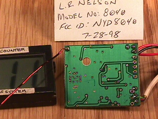
NYD8040Irrigation System Transceiver
L.R. Nelson Corporation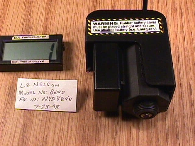
Click to zoom
Application Details
- Equipment Class
- DXT - Part 15 Low Power Transceiver, Rx Verified
- Date of Grant
- Sep 01, 1998
- Application Purpose
- Original Equipment
- Date of Application
- Aug 05, 1998
- Equipment Note
- Irrigation System Transceiver
- Frequency Range
- 916.50000000 - 916.50000000
- Company
- L.R. Nelson Corporation
- Country
- United States
Documents & Files
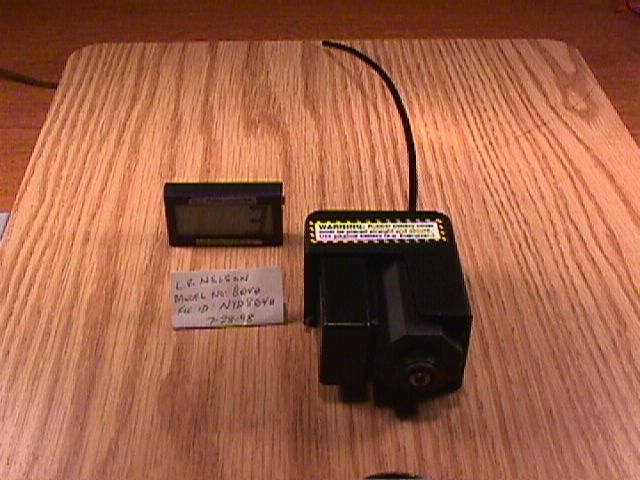
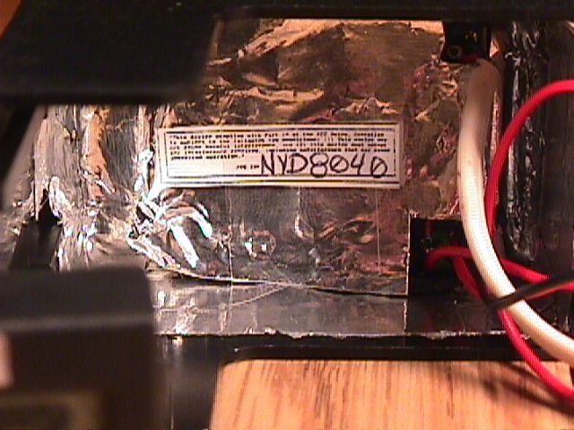
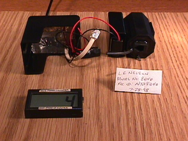
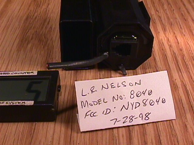
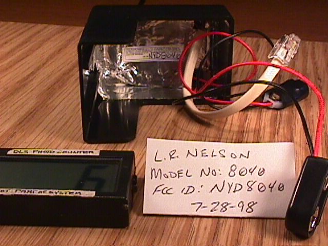
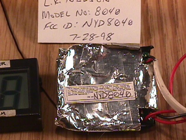
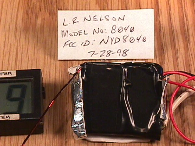
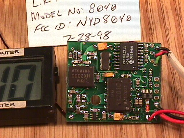
Document Text
Text extracted from the exhibit documents filed with the FCC. Open a document above to read the original.
Users Manual
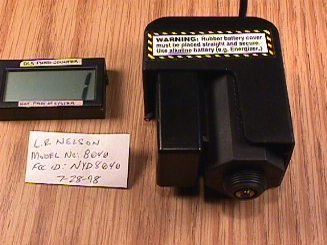
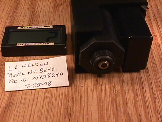
SoloRain TM RPA Radio Adapter Model 8040 Fig 0 goes here 900-06462 Rev 6-98 1998 L.R. Nelson Corporation INTRODUCTION Thank you for selecting the Nelson SoloRain 8040 RPA Radio Adapter. Please read the following instructions carefully to get familiar with important precautions and installation instructions. If you have any questions regarding your SoloRain RPA Radio Adapter please call our technical assistance hotline 800-NELSON8 (inside USA) or 309-690-2200 (outside USA). INSTALLATION The 8040 PG Radio Adapter can be installed with the Model 8030 Remote Programmable Actuator. For this installation you will need the 8040 RPA Radio adapter, the 8030 RPA, your 8081 Radio Programmer Plus, and a high quality 9V alkaline battery such as Energizer TM *, 2 leak-proof connectors, wire cutters, and pliers Please follow the following steps to correctly install the 8040 RPA Radio Adapter. Refer to figure I as needed. Step 1) Connect the coiled telephone cord from the Model 8081 Radio Programmer Plus into the telephone jack inside the 8040 RPA Radio Adapter. Step 2) Cut the red and black wires halfway between the battery case cap and the black protective covering as shown in figure 1. Do not strip the wires. Step 3) Insert all 3 red wires into the leak-proof connector supplied. Make sure all 3 red wires are fully inserted in the connector. Crimp the connector firmly. Step 4) Insert all 3 black wires into the leak-proof connector supplied. Make sure all 3 black wires are fully inserted into the connector. Crimp the connector firmly. Step 5) Connect the 9V battery to the battery connector. The 8081 should now indicate a connection to the 8030 RPA. Step 6) Place 9V battery into the battery compartment and press the battery case cap securely onto the battery case. Step 7) You must input a 3 digit actuator ID (identification) – Use key on the 8081 Programmer to display the menu. Choose 5 "Actuator ID" from the menu on the 8081 Programmer and input the code. Use to return to the menu. Each actuator in the system must have a unique ID for proper radio operation. You must remember the 3 digit ID in order to radio connect to this unit. The ID can be reset at any time by connecting with the telephone cord and choosing "Actuator ID" from the menu. Step 8) Disconnect the coiled telephone plug from the telephone jack inside the 8030 RPA. Step 9) Connect the 8040 telephone cord to the telephone jack inside the 8030 RPA. Step 10) Secure the 8040 RPA Adapter onto the 8030 RPA Figures 1,2 and 3 go here * (Energizer TM is the registered trademark of the Eveready Battery Co., Inc.) COMMUNICATION The RPA/8040 unit can now communicate with the 8081 Programmer unit. All programming and manual operations can now be controlled via the 8081 Programmer radio connection. The range of signal will be between 6 meters installed in ground and 30 meters above ground. Actual performance will depend on terrain and the installation configuration. The RPA/8040 unit has 2 levels of security to protect against tampering. 1) You must know the Actuator ID to connect with the unit. 2) The 8081 Programmer has a 4 digit "Programming code" that is set by the user. This code is automatically input to the PG Multi-Station Actuator when the Actuator ID was set. If the "Programming code" has been changed you must connect by telephone cord to the PG Multi-Station Actuator to reset the code. INFORMATION TO USER (Section 15.21) The user is cautioned that any changes or modifications not expressly approved by the party responsible for compliance could void the user's authority to operate this equipment. FCC ID: NYD8040 This device complies with part 15 of the FCC rules. Operation is subject to the following two conditions: (1) This device may not cause harmful interference, and (2) this device must accept any interference received, including interference that may cause undesired operation. NELSON WARRANTY Standard electronics warranty verbiage
Cover Letter(s)
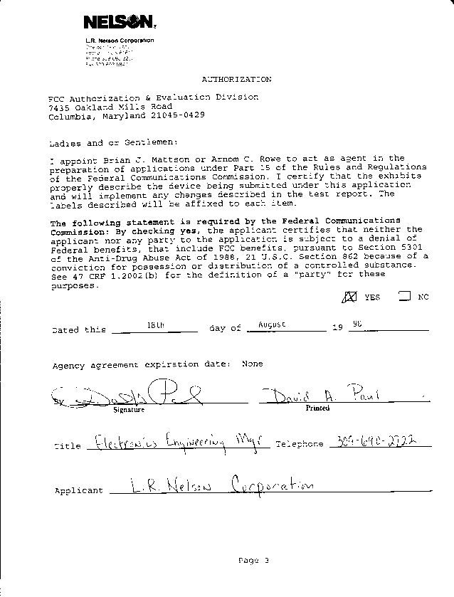
D.L.S. ELECTRONIC SYSTEMS, INC. 1250 Peterson Drive Wheeling, Illinois 60090 FEDERAL COMMUNICATIONS COMMISSION EQUIPMENT APPROVAL SERVICES P.O. Box 358315 Pittsburgh, Pennsylvania 15251-5315 Dear Ladies and/or Gentlemen: We are submitting for L.R. Nelson Corporation, a Commercial and Consumer Irrigation System, having a Model Number of 8040, and an FCC ID Number NYD8040 for Certification. This unit has been tested and complies to Part 15, Subpart B. If there are any questions in regards to this application, please call D.L.S. Electronic Systems, Inc. at (847) 537- 6400. Enclosed you will find a check for $895.00 to pay for this application as required. Please forward this application to: Federal Communications Commission Authorization and Standards Division 7435 Oakland Mills Road Columbia, Maryland 21046 Thank you for your assistance in this matter. Sincerely, Arnom C. Rowe EMC Engineer EMC-001375-NE ACR/km
Operational Description
L.R.Nelson Corporation Jul-98 Description of the Transmitter and Receiver used in L.R.Nelson Solorain Product Line The receiver and transmitter units are housed on a single printed circuit board to make up a digital transceiver. The 8060, 8040 and 8081 use the same receiver and transmitter chip sets. The 8060 and 8040 also incorporate an 8-bit microcontroller to encode and decode data to and from another transceiver pair. The 8060 and 8040 transceivers will reside on small, battery powered water valve controllers used for commercial and consumer irrigation systems. The transceivers will enable wireless programming of the intelligent water valves using a battery powered console incorporating an 8081 transceiver radio. In most applications, the intelligent water valves will be housed underground within irrigation valve enclosures. The handheld consoles will be used by irrigation contractors to program the intelligent valves as needed. Both the console and intelligent water valve incorporate microcontroller technology. Present communication between the two devices is accomplished using a three-wire serial connection. Wireless transmission will modulate the digital serial data using an OOK (On-Off Keying) technique. A mark symbol is represented in the presence of a sine wave carrier and a space symbol is the absence of that carrier. The console and intelligent water valve will operate the transceiver units in the same manner as the three-wire connection.
Test Report
D.L.S. ELECTRONIC SYSTEMS, INC. 1250 PETERSON DRIVE WHEELING, ILLINOIS 60090 REPORT NO. 6769 FCC "Rules and Regulations", Part 15, Subpart C Sections 15.249, 15.207 & 15.209 General Requirements Intentional Radiators Operation within the frequency range 902-928 MHz, 2400-2483.5 MHz, 5725 to 5875 MHz, & 24.0 to 24.25 GHz THE FOLLOWING "MEETS" THE ABOVE TEST SPECIFICATION Formal Name: Nelson SoloRain 8040 RPA Radio Adapter Kind of Equipment: Commercial and Consumer Irrigation Systems Test Configuration: NA FCC ID Number: NYD8040 Model Number: 8040 Serial Number: NA Dates of Test: July 22 & 23, 1998 Test Conducted For: L. R. Nelson Corporation One Sprinkler Lane Peoria, Illinois 61615 NOTICE: Please see change information listed inside this report. This report must not be reproduced (except in full), without the approval of D.L.S. Electronic Systems, Inc. Page 1 D.L.S. ELECTRONIC SYSTEMS, INC. 1250 PETERSON DRIVE WHEELING, ILLINOIS 60090 REPORT NO. 6769 SIGNATURE PAGE Page 2 INSERT NVLAP CERTIFICATE OF ACCREDITATION Page 3 INSERT NVLAP SCOPE OF ACCREDITATION Page 4 INSERT PUBLIC NOTICES (Page 1) Page 5 INSERT PUBLIC NOTICES (Page 2) Page 6 D.L.S. ELECTRONIC SYSTEMS, INC. REPORT NO. 6769 TABLE OF CONTENTS Page Contents Paragraph 1. Cover Page.............................................i 2. Signature Page........................................ii 3. NBS Certificate of Accreditation.....................iii 5. Public Notices........................................iv 7. Table of Contents.....................................vi 8. Summary of Test Report...............................1.0 8. Introduction.........................................2.0 8. Object...............................................3.0 9. Test Set-up..........................................4.0 9. Test Equipment (Bandwidths and Detector Function)....5.0 10. Conducted Emission Measurements......................6.0 10. Radiated Emission Measurements.......................7.0 11. Restricted Bands.....................................8.0 12. Photo Information and Test Set-Up....................9.0 13. Photos Taken During Testing.........................10.0 15. Change Information..................................11.0 16. Results of Tests....................................12.0 16. Conclusion..........................................13.0 17. Equipment List...................................TABLE 1 18. Data Summary..................................Appendix A 19. Charts taken during testing...................Appendix B Page 7 D.L.S. ELECTRONIC SYSTEMS, INC. EMC TEST SERVICES REPORT NO. 6769 Kind of Equipment: Commercial and Consumer Irrigation Systems S/N: NA 1.0 SUMMARY OF TEST REPORT It was found that the Nelson SoloRain 8040 RPA Radio Adapter, S/N NA "meets" the radio interference emission requirements of the FCC "Rules and Regulations", Part 15, Subpart C, Sections 15.249, 15.207 & 15.209, for Intentional Radiators used in the frequency bands 902 to 928 MHz. It should be noted that the amount of margin was only 1.82 dB at 5498.5 MHz, radiated. The normal tolerance of the test equipment is + or - 3 dB. Due to this tolerance and the variation in normal production, a margin of at least 4 dB is recommended. With only a 1.82 dB margin, there is a probability that if this or another unit were tested by the Domestic or Foreign Compliance Regulatory Agency using similar equipment, it could be found to not meet the above requirement. 2.0 INTRODUCTION On July 22 & 23, 1998, a series of radio frequency interference measurements were performed on Commercial and Consumer Irrigation Systems, S/N NA. The tests were performed according to the procedures of the FCC as stated in the "Methods of Measurement of Radio-Noise Emissions from Low-Voltage Electrical and Electronic Equipment in the Range of 9 kHz to 40 GHz" found in the American National Standards Institute, ANSI C63.4-1992 (Revision of ANSI C63.4-1988). Tests were performed by personnel of D.L.S. Electronic Systems, Inc. who are responsible to Donald L. Sweeney, Senior EMC Engineer. 3.0 OBJECT The purpose of this series of tests was to determine if the test sample could meet the radio frequency emission requirements of the FCC "Rules and Regulations", Part 15, Subpart C, Sections 15.33, 15.207, 15.209, & 15.249 (a-d), for Intentional Radiators used in the frequency bands 902 to 928 MHz. Page 8 D.L.S. ELECTRONIC SYSTEMS, INC. EMC TEST SERVICES REPORT NO. 6769 4.0 TEST SET-UP All conducted emission tests were performed in a shield enclosure or lab at D.L.S. Electronic Systems, Inc. The conducted tests were performed with the test item placed on a wooden table located in the Test Room. The power line supplied was connected to a dual line impedance stabilization network located on the floor, a ground plane. The networks were constructed per the requirements of the American National Standards Institute, ANSI C63.4-1992, Section 4, (Figure 2). The only ground supplied to the unit was through the third wire of the standard power cord when supplied. 5.0 TEST EQUIPMENT (Bandwidths and Detector Function) All preliminary data below 1000 MHz was automatically plotted using the HP 8566B Spectrum Analyzer. This data was taken using the Peak or CISPR Detector Functions. This information was then used to determine the frequencies of maximum emissions. Above 1000 MHz final data was taken using the Peak Detector. Below 1000 MHz final data was taken using the EMC-25 fixed tuned receiver. Plots were made using the Peak Detector, with manual measurements made on the frequencies of interest, using the Peak and CISPR Detector Functions of the receiver. The actual detector used is indicated on the spreadsheets found in the Data Summary Section of this report. The bandwidths used are specified by the FCC as stated in the American National Standards Institute, ANSI C63.4-1992, Section 4.2. From 30 MHz to 1000 MHz a bandwidth of 120 kHz was used, and above 1000 MHz, a bandwidth of 1 MHz was used. A list of the equipm…
Text truncated - open the document above for the full version.
Contact Information
Applicant
David A. Paul(Electronics Engineering Manager)
309-690-2722
Technical Contact
DLS Electronic Systems, Inc.Arnom (Arnie) C Rowe
[email protected]847-537-6400
1250 Peterson Drive · Wheeling, Illinois · United States
Test Firm
DLS Electronic Systems, Inc.Donald Sweeney
847-537-6400
Technical Specifications
| # | Rule Parts | Frequency Range | Power Output |
|---|---|---|---|
| 1 | 15C | 916.5 MHz - 916.5 MHz | - |
Other Applications from L.R. Nelson Corporation
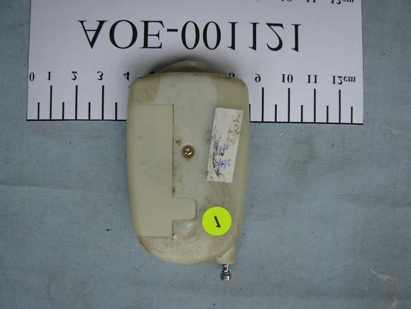
NYD5917
Aug 21, 2006REMOTE RAIN
Equipment Class
DSC - Part 15 Security/Remote Control Transmitter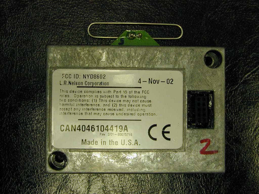
NYD8602
Feb 11, 2003Lawn Sprinkler Controller
Equipment Class
DSS - Part 15 Spread Spectrum Transmitter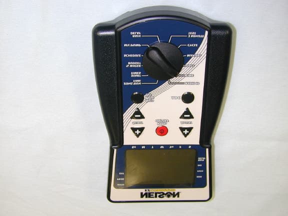
NYD8600
Apr 24, 2001EZ Pro Command Irrigation Controller
Equipment Class
DSS - Part 15 Spread Spectrum Transmitter
NYD86XX
Apr 11, 2001EZ Pro Electronic Irrigation Controller
Equipment Class
DSS - Part 15 Spread Spectrum Transmitter
NYD8060
Sep 01, 1998Irrigation System Transceiver
Equipment Class
DXT - Part 15 Low Power Transceiver, Rx Verified