NYD8602Lawn Sprinkler Controller
L.R. Nelson Corporation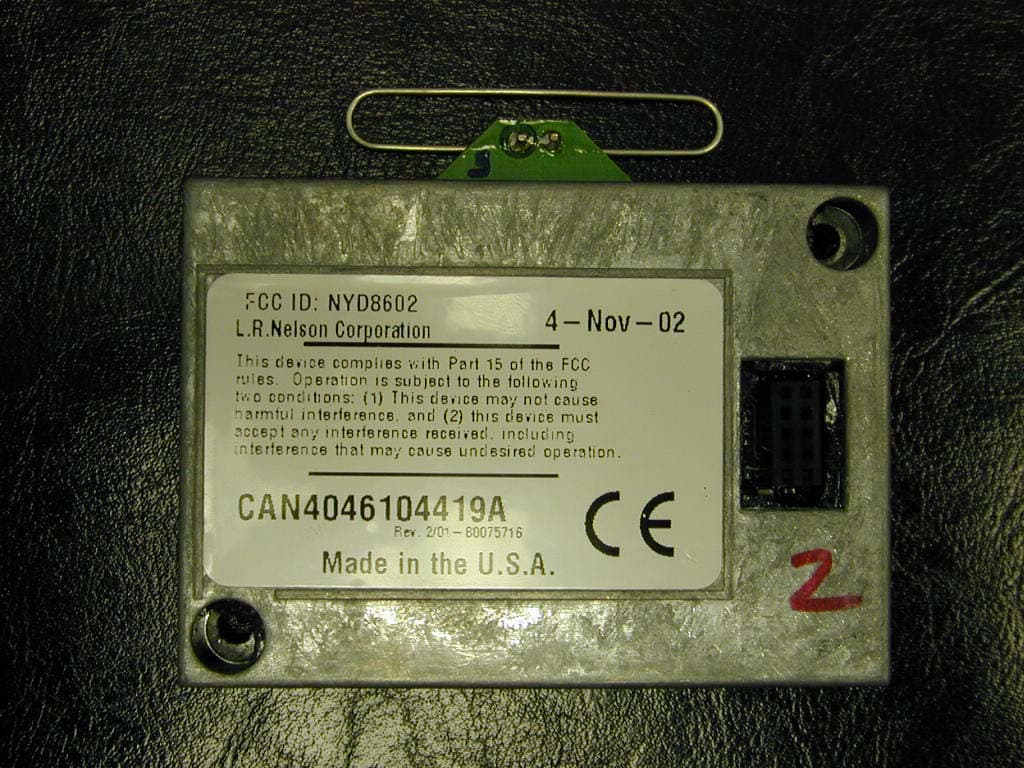
Click to zoom
Application Details
- Equipment Class
- DSS - Part 15 Spread Spectrum Transmitter
- Date of Grant
- Feb 11, 2003
- Application Purpose
- Original Equipment
- Date of Application
- Feb 11, 2003
- Equipment Note
- Lawn Sprinkler Controller
- Frequency Range
- 2455.00000000 - 2467.00000000
- Company
- L.R. Nelson Corporation
- Country
- United States
Documents & Files
Document Text
Text extracted from the exhibit documents filed with the FCC. Open a document above to read the original.
Users Manual
L.R. Nelson Corporation One Sprinkler Lane Peoria, IL 61615 OEM Manual 8602 Radio Module - 1 - General Information The 8602 module was designed for point to point operation between a pair of modules, one designated as master and the other designated as slave. Point to multi-point is not supported. Features • The Radio module contains it’s own shielding, alleviating the need for the final product that the module is used in from having to have it’s own shielding. • All operations of the radio portion of the unit are controlled by the on-board micro controller and thus transparent to the system integrator. All that is required is to issue serial commands. • The power supplies to the RF portions of the radio are regulated on-board alleviating the need for strict power supply regulation to maintain compliance. • The antenna is permanently attached to the unit, alleviating the need for additional labor installing an antenna. L.R. Nelson Radio Transceiver Radio Frequency ISM 2.4 GHz Frequency Range 2.455-2.467 GHz Type FHSS Power Output 30mW Receiver Sensitivity -105dBm Range LOS 1000ft/300m Air Baud Rate 2400bps Operating Temp -23 to 65°C Storage Temp -29 to 80°C Power Consumption (5V) idle 40mA, Rx 110mA, Tx 170mA Hardware Interface TTL Serial, 9600b, 8 data, 1 stop, no parity Software Interface Nelson Serial Protocol L.R. Nelson Corporation One Sprinkler Lane Peoria, IL 61615 OEM Manual 8602 Radio Module - 2 - Requirements for compliance • The antenna must be kept intact to maintain compliance. Alternative antennae are not supported. • The metal housing must be kept intact to maintain the module’s shielding properties. The module must be kept unmodified as received except for straightening the antenna if it is received out-of-shape due to shipping. • If the FCC ID tag is not visible when the module is installed, then the outside of the device into which the module is installed must display a label referring to the enclosed module. Wording such as “Contains Module FCC ID NYD8602” or “Contains FCC ID NYD8602” is sufficient. The external label must also contain the wording “This device complies with Part 15 of the FCC rules. Operation is subject to the following two conditions: (1) This device may not cause harmful interference, and (2) this device must accept any interference received, including interference that may cause undesired operation. • The final product that the module is used in may be subject to other certifications not covered by the module certification such as computer accessories, etc. • A power supply module is not supplied for the radio, therefore if it is powered by an AC source other than an EZ Pro controller, the product would be subject to testing for power-line conducted emissions. EXPOSURE NOTICE This device generates and radiates radio-frequency energy. In order to comply with FCC radio-frequency radiation exposure guidelines for an uncontrolled environment, this equipment has to be installed and operated while maintaining a minimum body to antenna distance of 2.5 cm." • Instructions must be provided to the OEM to place a statement, similar to the one above, in their manual. This statement is to inform the end users that this device does generate RF energy. The end user must be made aware of the potential exposure to RF energy. L.R. Nelson Corporation One Sprinkler Lane Peoria, IL 61615 OEM Manual 8602 Radio Module - 3 - Life Support Application These products are not designed for use in life support appliances, devices, or systems where malfunction of these products can reasonably be expected to result in personal injury. L.R. Nelson customers using or selling these products for use in such applications do so at their own risk and agree to fully indemnify L.R. Nelson for any damages resulting from such improper use or sale. 8602 Installation and Operation Tips The 8602 Radio Module has been designed to provide the best performance possible in a wide variety of applications. The installation of the 8602 Radio Module can be of great impact on the actual performance of the radio system. The structural material of the building, the installation location in the building, local terrain, and local conditions can have a dramatic effect on the range of signal. The following tips can be very useful in gaining the best performance and range from the radio. Generally the user can expect range to be 1000 feet line of sight and 500 feet through wooden structures such as a home. Installing an 8602 Radio Module It is important to remember per the instructions to disconnect power to the device receiving the module before plugging in the 8602 Radio Module. Gently seat the 8602 into the connector on the interconnect board and install the two screws. Reconnect the AC power. Radio Usage Guidelines It is important to understand that at any particular installation we expect the performance of the radio will meet the needs of the user. The following are general guidelines. • Outside on a pedestal, pole, or roof top will provide maximum range and performance.-Best range • Mounted on an outside wall of the building. Depending on the type of structure the range on the opposite side of the building could be reduced. L.R. Nelson Corporation One Sprinkler Lane Peoria, IL 61615 OEM Manual 8602 Radio Module - 4 - The signal must pass clear through the structure to get out the other side. –Good range • Mounted on the inside of an exterior wall of a building. –Reduced range • Mounted inside of a building with more than one wall to pass through before signal reaches outdoors. -Further reduces range • Mounting higher is usually better than lower. It would be preferable to mount the controller above ground rather than in a basement. • A larger building with more walls will effect range more than a small building with only a few walls. Type of Structure The construction material of the building can have an effect on range and performance. Wood and glass will reduce the signal. Any type of metal can greatl…
Text truncated - open the document above for the full version.
Block Diagram
Ceramic Band Pass Filter 2.45GHz Center 90MHz Bandwidth System Clock 20MHz Folded Dipole Antenna Active Mixer 2 Pole Band Pass Filter 2.45GHz Center PLL Frequency Synthesizer 4 Pole Band Pass Filter 374 MHz Center Gain Active Mixer 10.7 MHz Ceramic Filter Gain DDS Frequency Synthesizer Modulator Limiter 10.7 MHz Ceramic Filter Discriminator Demodulator Post Detection Filter MicroController Matched Filter Clock Recovery Active Mixer 2 Pole Band Pass Filter 2.45GHz Center RS232 Input Data RS232 Output Data +5V Power 3.3V Reg TX/RX Switch VCC
Cover Letter(s)
REQUEST FOR CONFIDENTIALITY L.R. Nelson Corp requests confidentiality with regard to the following documents in the filing for equipment approval identified by FCC ID. No. NYD8602. (1) Schematic diagrams contained in electronic file identified as Nelson 86xx radio_schematic.pdf. It is the opinion of L.R. Nelson Corp disclosure of this information would result in significant loss of revenue. This information should be kept confidential for 3 years. NOTE: Only information that is not accessible to the general public may be held confidential. Generally internal and external photos cannot be held confidentiality. The exception would be if the PC board is potted.
Operational Description
Aaron Coakley 2/12/2003 L.R. Nelson Confidential Circuit Description for EZ Pro Radio Module 8602 General Description The 8602 radio module is a 2.4GHz digital spread spectrum frequency modulating hopping transceiver. Operation of the module is controlled by an on-board MCU. The MCU operates at 20.00MHz and controls all radio functions of the TI TRF6900 transceiver chip and Intersil HFA3683 upconvertor / downconvertor based upon the serially issued requests of the host system. MCU-MCU data rate is 9600bps-n-8-1, and radio-radio data rate is 2400bps. Base The base module is placed into a listen mode by a serial command and ID set from the controlling system. During this listen mode, the receiver hops around the pseudorandom frequencies within the hop group identified by the ID set, dwelling longer than a typical data packet frame, and will respond to a matching ID set, establishing a connection. The base will return to dwell if the connection is lost or if commanded by the controlling system. Remote The remote module is commanded by the controlling system to establish communication by serially issuing a “slave connect” command and an ID set for the module for which it desires communication. The remote will transmit the ID set and additional data indicating that it is requesting a connection. Once connected, the radio will enter a “connected” state and will pass the requested data back and forth. Radio operation The ID set defines the overall frequency band the radio will operate in, and will be one of the following: 2454-2465, 2455-2466, 2456-2467, 2457-2468. The 20MHz system clock is upconverted by the PLL in the Intersil part to the base frequencies of 2084, 2085, 2086, or 2087MHz as directed by the MCU. TI TRF6900 generates a frequency of 370.9775MHz to 380.2425MHz as directed by the MCU for transmit or 360.2775 to 369.5425 for receive. During transmit, the MCU directs the TI transceiver to transmit the desired channel number, along with Manchester encoded FM data which is then upconverted by the Intersil device. During receive, the TI device is commanded to 10.7MHz below the transmit frequency of the desired channel. During receive, the incoming RF signals are downconverted by the Intersil device and demodulated by the TI transceiver. The bit recovery and bit sync are performed within the controlling MCU. The packet data contains either data requested by the base or remote system, or connection data to keep the link active and in sync along with the ID set, dotting and error detection bytes. If sync is lost, the base unit will return to a dwell mode and the remote will attempt to re-establish the link.
Test Report
Nemko Test Report: 2L0452RUS1 Applicant: L.R. Nelson Corp. One Sprinkler Lane Peoria, IL 61615-9544 Equipment Under Test: EZ Pro, Model 8602 (E.U.T.) In Accordance With: FCC Part 15, Subpart C, 15.247 Frequency Hopping Transmitters Tested By: Nemko Dallas Inc. 802 N. Kealy Lewisville, Texas 75057-3136 Authorized By: Tom Tidwell, RF Group Manager Date: 12/12/02 Total Number of Pages: 56 Nemko Dallas FCC PART 15, SUBPART C FREQUENCY HOPPING SPREAD SPECTRUM TRANSMITTER EQUIPMENT: EZ Pro, Model 8602 PROJECT NO.: 2L0452RUS1 Page 2 of 56 Table of Contents Section 1. Summary of Test Results ........................................................................................... 3 Section 2. Equipment Under Test (E.U.T.)................................................................................. 5 Section 3. Powerline Conducted Emissions ............................................................................... 7 Section 4. Channel Separation .................................................................................................. 11 Section 5. Pseudorandom Hopping Algorithm ......................................................................... 13 Section 6. Time of Occupancy..................................................................................................29 Section 7. Occupied Bandwidth................................................................................................ 32 Section 8. Peak Power Output ..................................................................................................36 Section 9. Spurious Emissions (Radiated) ................................................................................. 38 Section 10. Test Equipment List............................................................................................... 43 ANNEX A - TEST DETAILS ........................................................................................................ 44 ANNEX B - TEST DIAGRAMS.................................................................................................... 54 Nemko Dallas FCC PART 15, SUBPART C FREQUENCY HOPPING SPREAD SPECTRUM TRANSMITTER EQUIPMENT: EZ Pro, Model 8602 PROJECT NO.: 2L0452RUS1 Page 3 of 56 Section 1. Summary of Test Results Manufacturer: L.R. Nelson Corp. Model No.: EZ Pro, Model 8602 Serial No.: None General: All measurements are traceable to national standards. These tests were conducted on a sample of the equipment for the purpose of demonstrating compliance with Part 15, Subpart C, Paragraph 15.247 for Frequency Hopping Spread Spectrum devices. Radiated tests were conducted is accordance with ANSI C63.4-1992. Radiated emissions are made on an open area test site. A description of the test facility is on file with the FCC. New Submission Production Unit Class II Permissive Change Pre-Production Unit Family Listing THIS TEST REPORT RELATES ONLY TO THE ITEM(S) TESTED. THE FOLLOWING DEVIATIONS FROM, ADDITIONS TO, OR EXCLUSIONS FROM THE TEST SPECIFICATIONS HAVE BEEN MADE. See “ Summary of Test Data”. NVLAP LAB CODE: 100426-0 Nemko Dallas Inc. authorizes the above named company to reproduce this report provided it is reproduced in its entirety and for use by the company’s employees only. Any use which a third party makes of this report, or any reliance on or decisions to be made based on it, are the responsibility of such third parties. Nemko Dallas Inc. accepts no responsibility for damages, if any, suffered by any third party as a result of decisions made or actions based on this report. This report applies only to the items tested. Nemko Dallas FCC PART 15, SUBPART C FREQUENCY HOPPING SPREAD SPECTRUM TRANSMITTER EQUIPMENT: EZ Pro, Model 8602 PROJECT NO.: 2L0452RUS1 Page 4 of 56 Summary Of Test Data NAME OF TEST PARA. NO. SPEC. MEAS. RESULT Powerline Conducted Emissions 15.207(a) 48 dBμV 23.05 dBuV Complies Channel Separation 15.247(a)(1) Greater of 25 kHz or 20 dB Bandwidth 85 kHz Complies Pseudorandom Hopping Algorithm 15.247(a)(1) Customer Supplied Customer Supplied Customer Supplied Time of Occupancy 15.247(a)(1)(ii) ≤ 0.4 sec in 30 sec 0.3 sec in 30 sec. Complies 20 dB Occupied Bandwidth 15.247(a)(1) ≤ 1 MHz Complies Peak Power Output 15.247(b) 4 Watts EIRP 29.5 mW Complies Spurious Emissions (Antenna Conducted) 15.247(c) -20 dBc N/A N/A Spurious Emissions (Radiated) 15.247(c) Table 15.209(a) See Data Complies Footnotes: The device does not have a detachable antenna. Nemko Dallas FCC PART 15, SUBPART C FREQUENCY HOPPING SPREAD SPECTRUM TRANSMITTER EQUIPMENT: EZ Pro, Model 8602 PROJECT NO.: 2L0452RUS1 Page 5 of 56 Section 2. Equipment Under Test (E.U.T.) General Equipment Information Frequency Band: 2455 to 2467 MHz Number of Channels: 75 Channel Spacing: 85 kHz User Frequency Adjustment: Software controlled Nemko Dallas FCC PART 15, SUBPART C FREQUENCY HOPPING SPREAD SPECTRUM TRANSMITTER EQUIPMENT: EZ Pro, Model 8602 PROJECT NO.: 2L0452RUS1 Page 6 of 56 Theory of Operation The 8602 module was designed for point to point operation between a pair of modules, one designated as master and the other designated as slave. Point to multi-point is not supported. System Diagram Nemko Dallas FCC PART 15, SUBPART C FREQUENCY HOPPING SPREAD SPECTRUM TRANSMITTER EQUIPMENT: EZ Pro, Model 8602 PROJECT NO.: 2L0452RUS1 Page 7 of 56 Section 3. Powerline Conducted Emissions NAME OF TEST: Powerline Conducted Emissions PARA. NO.: 15.207(a) TESTED BY: David Light DATE: 12/9/2002 Test Results: Complies. Measurement Data: See attached plots. Measurement Uncertainty: +/- 0.7 dB Nemko Dallas FCC PART 15, SUBPART C FREQUENCY HOPPING SPREAD SPECTRUM TRANSMITTER EQUIPMENT: EZ Pro, Model 8602 PROJECT NO.: 2L0452RUS1 Page 8 of 56 Test Data - Powerline Conducted Emissions Dallas Headquarters: 802 N. Kealy Lewisville, TX 75057 Tel: (972) 436-9600 Fax: (972) 436-2667 Nemko Dallas, Inc. Data Plot Page 1 of 2 Complete X Job No.:2L0452RDate:12/9/2002Preliminary: Specification:15.207Temperature(°C):22 Tested By:Davi…
Text truncated - open the document above for the full version.
Contact Information
Applicant
David A. Paul(Electronics Engineering Manager)
309-690-2722
Technical Contact
Nemko Dallas, Inc.David Light
[email protected]972-436-9600
802 N. Kealy · Lewisville, Texas · United States
Non-Technical Contact
Nemko Dallas, Inc.David Light
[email protected]972-436-9600
Test Firm
Nemko Dallas, Inc.Michael Cantwell
Technical Specifications
| # | Rule Parts | Frequency Range | Power Output |
|---|---|---|---|
| 1 | 15C | 2.46 GHz - 2.47 GHz | 30.00 mW |
Other Applications from L.R. Nelson Corporation
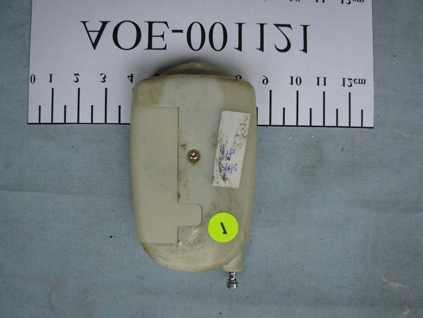
NYD5917
Aug 21, 2006REMOTE RAIN
Equipment Class
DSC - Part 15 Security/Remote Control Transmitter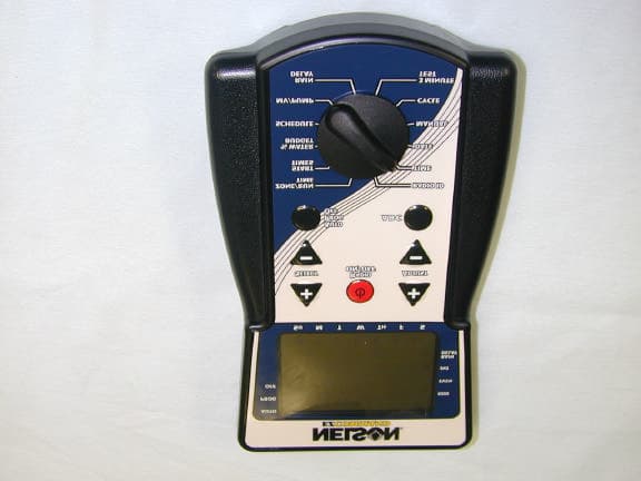
NYD8600
Apr 24, 2001EZ Pro Command Irrigation Controller
Equipment Class
DSS - Part 15 Spread Spectrum Transmitter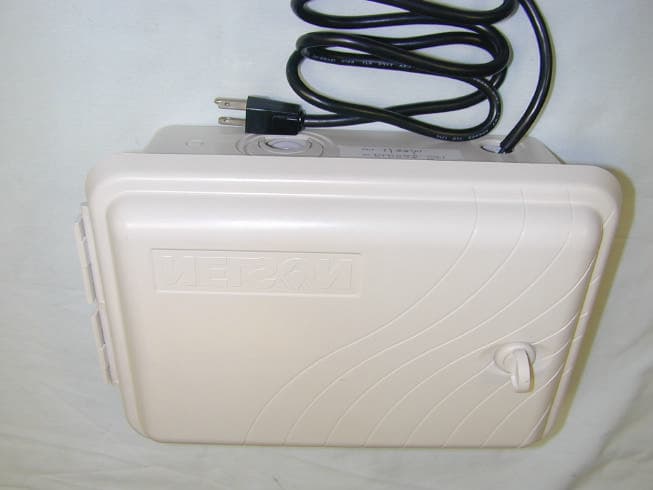
NYD86XX
Apr 11, 2001EZ Pro Electronic Irrigation Controller
Equipment Class
DSS - Part 15 Spread Spectrum Transmitter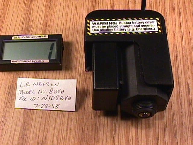
NYD8040
Sep 01, 1998Irrigation System Transceiver
Equipment Class
DXT - Part 15 Low Power Transceiver, Rx Verified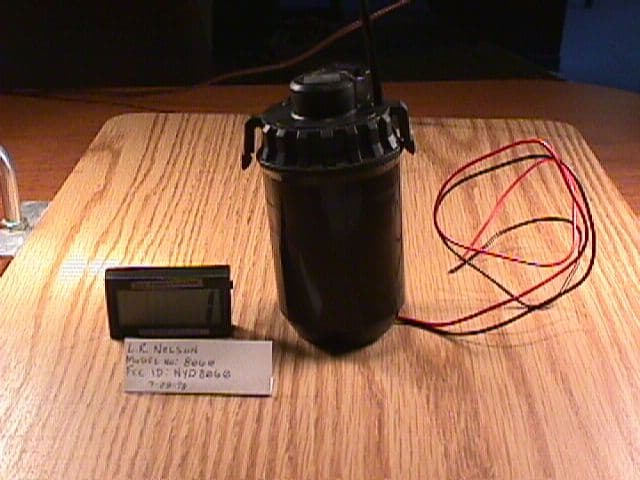
NYD8060
Sep 01, 1998Irrigation System Transceiver
Equipment Class
DXT - Part 15 Low Power Transceiver, Rx Verified