NYD8600EZ Pro Command Irrigation Controller
L.R. Nelson Corporation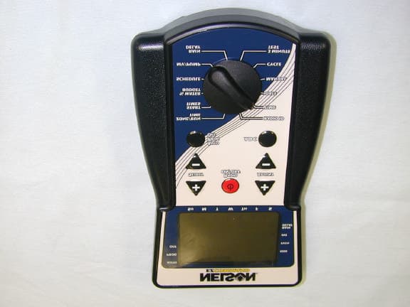
Click to zoom
Application Details
- Equipment Class
- DSS - Part 15 Spread Spectrum Transmitter
- Date of Grant
- Apr 24, 2001
- Application Purpose
- Original Equipment
- Date of Application
- Apr 24, 2001
- Equipment Note
- EZ Pro Command Irrigation Controller
- Frequency Range
- 2400.00000000 - 2483.50000000
- Company
- L.R. Nelson Corporation
- Country
- United States
Documents & Files
Document Text
Text extracted from the exhibit documents filed with the FCC. Open a document above to read the original.
Users Manual
8.5x11 folded once english, spanish,french, german,portugese,italian EZ Command Remote Programmer Model 8600 INSTALLATION AND PROGRAMMING GUIDE P/N 90007552 The EZ Command Remote Programmer is capable of controlling all EZ Pro controller functions including programming and manual zone operation via a secure radio link. There can be a tremendous timesaving when installing, servicing and operating a Nelson EZ Pro irrigation system by using this technology. Battery Installation Remove the screw on the battery cover and remove the battery cover. Install two new “C” (LR14 in Europe) size alkaline batteries. Replace the battery cover and screw. Low Battery Indicator There is a Low Battery Warning symbol (Pudik show the symbol Low battery warning from page 22 EZ Pro instructions) on the EZ Command LCD. When this is displayed and flashing new batteries must be installed in your EZ Command. Note: When radio connected to the EZ Pro if the Low Battery Warning symbol is displayed it means new batteries must be installed in the EZ Pro Turn the EZ Command Remote Programmer On and Off Turn on the EZ Command Remote Programmer by pressing any key or moving the dial to any position. After 1 minutes of non-use the unit will automatically turn off. To turn the unit off when radio connected press the Radio On/ Off key. EZ Pro Radio Setup A four digit Controller ID and a four digit Programmer Code must be programmed into the EZ Pro controller prior to making a radio connection. Once set the controller will store these in memory and a radio connection can be made at any time. 0000 0000 Controller ID (0000 to 9999) Programmer Code (0000 to 9999) AUTO PROG OFF Controller ID- Every controller must have a unique ID. This will prevent a conflict if more than one controller is within range of the radio signal. Write down the Controller ID for future reference. Warning: Do not select the same Controller ID for two controllers within 1 mile of each other. Improper radio operation may result. Programmer Access Code- Use the same Programmer Code for all of your EZ Pro controllers and EZ Command Remote Programmers. This Code provides the security to prevent unwanted radio access. Reminder: Use the same Programmer Code on all of your EZ Pro controllers and EZ Command Programmers Set a Controller ID and Programmer Code on the EZ Pro Controller Set the Mode dial on the EZ Pro controller to the Program position. Turn the large dial on the EZ Pro controller to the Radio Setup position. Use the SELECT +- to move between Controller ID and Programmer Code. Use the ADJUST +- keys to set these as you choose. Return the Mode dial to the OFF or Auto position Pudik show figure 3 from EZ pro instructions here Connecting by Radio with the EZ Command Remote Programmer When the EZ Command Remote Programmer is turned on the LCD screen displays the last Controller ID and Programmer Access Code used. Use the Select and Adjust +- keys to choose the Controller ID and Programmer Code to match the controller you wish to connect to. Press the Radio ON /OFF button to make the connection. Note: There must be AC power to the EZ Pro in order to make a radio connection. Connection Screen When connected the Radio Connected ( Pudik show symbol)symbol will show on both the EZ Command unit and on the EZ Pro. The LCD display will show the time and current status of the EZ Pro. The LCD screen will display the EZ Pro’s Mode Dial position (Auto, Program, or Off) and Program Dial position (A, B, or C). If there are any zone problem messages these will be displayed on the LCD. If there is a Rain Delay Programmed or the Rain Sensor is activated these will be displayed. The EZ Command LCD will display all programming or operation commands exactly as seen on the EZ Pro controller. This instant feedback assures that the EZ Pro controller retains any changes you make. While radio connected the EZ Command will temporarily override dial settings and status of the EZ Pro. All manual and programming functions of the EZ Pro can be controlled from the EZ Command Remote Programmer. Range of Radio Signal Radio signal range is greatest when there is a clear line of sight between the EZ Pro and the EZ Command. The type and size of structure that the EZ Pro is located in as well as the local terrain may effect performance. Connected Operation After one minute of use without a dial turn or a button press the EZ Command will enter a “sleep” mode. This is to extend battery life. The unit will “wake” once a minute and update the LCD screen. Pressing any button or turning the dial will also “wake” the EZ Command. After 15 minutes of non-use the radio connection will stop and the EZ Command will turn off. You will need to connect to the EZ Pro again. Programming and Operating Instructions While radio connected use the Large dial, SELECT buttons, ADJUST buttons, A,B,C button and the AUTO, PROG, OFF button on the EZ Command to program and operate the EZ Pro controller as desired. See the EZ Pro TM Instruction book for all programming and operating instructions. Program changes made while radio connected are retained by the EZ Pro. Disconnecting from the EZ PRO To disconnect from the EZ Pro press the Radio On/ Off key. The radio will disconnect and the EZ Command unit will turn off. Once disconnected the EZ Pro will return to the previous status. Any program changes made will be saved in the EZ Pro. Note: A manual zone run, a Cycle, or a 3 Minute Test started by the EZ Command will continue after the radio is disconnected. The EZ Pro will return to its previous status after the operation is finished. Care of the EZ Command Avoid letting the EZ Command get wet. While it is water-resistant it is not waterproof. Water inside the unit will damage the circuitry. Do not drop the EZ Command. This may damage the unit. Troubleshooting and Service for the EZ Command SYMPTOMPOSSIBLE CAUSESOLUTION Unable to radio connect Controller ID and or Programmer Code do not match the EZ Pro controller Chec…
Text truncated - open the document above for the full version.
Block Diagram
General Information on EZ Pro Controller Models 8674( R ) through 8694( R ). LR Nelson Confidential Aaron CoakleyPage 103/09/01 General Description: The EZ Pro is an AC Powered Irrigation Controller. The Primary input voltage is stepped down from line voltage (120VAC 60Hz Domestic, 230VAC 50Hz Export) to 24VAC (nominal), which then energizes the DC power supply and supplies power for the zones. The secondary is protected by a 1A Raychem® polyswitch (self-resetting current limiter). A microcontroller aboard the Front Panel Module controls a user interface which consists of 3 knobs and a 4 button keypad. The microcontroller keeps time using a 32kHz quartz oscillator and schedules when to turn on the appropriate zones according to what was programmed in on the user interface. The microcontroller also supplies limited diagnostic information as to the presence or absence of a fault on a zone and discontinues opearation of a faulty zone. The outputs consist of 4 through 24 zones which can only be turned on one at a time, along with a secondary output (called the Pump/Master Valve) which may or may not be turned on based upon user programming. 86xxR models incorporate a radio module, which allows for extension of the user interface to a handheld device. The radio consists of a Zinc encased 2.4GHz Spread Spectrum Radio. All of the Models use an identical enclosure, transformer, and control electronics. The only major differences between models is the number of available zones, the type of enclosure lock, inclusion of radio module, and physical size of interconnect. Instructions will be supplied appropriate to the language of the country in which the unit is sold. A circuit breaker device will protect the input of the transformer since the transformer must be wired to local codes. A statement will be added to the instructions stating that a disconnect device must be wired to the primary input of the controller. Table of Export Model Numbers and their differences Differences ModelDescription # ZonesLockInterconnect 8674 4 Zone Irrigation Controller4PlasticSmall 8676 6 Zone Irrigation Controller6PlasticSmall 8678 8 Zone Irrigation Controller8PlasticSmall 8682 12 Zone Irrigation Controller12Metal KeyLarge 8686 16 Zone Irrigation Controller16Metal KeyLarge 8690 20 Zone Irrigation Controller20Metal KeyLarge 8694 24 Zone Irrigation Controller24Metal KeyLarge 8674 4 Zone Irrigation Controller with Radio Module4PlasticSmall 8676 6 Zone Irrigation Controller with Radio Module6PlasticSmall 8678 8 Zone Irrigation Controller with Radio Module8PlasticSmall 8682 12 Zone Irrigation Controller with Radio Module12Metal KeyLarge 8686 16 Zone Irrigation Controller with Radio Module16Metal KeyLarge 8690 20 Zone Irrigation Controller with Radio Module20Metal KeyLarge 8694 24 Zone Irrigation Controller with Radio Module24Metal KeyLarge General Information Transformer Output Current1.25A PolySwitch protection1A Microprocessor primary oscillator32.768 kHz Microprocessor secondary oscillator4.194304 MHz Tested Enclosure is the same material that will be used in production GE Cycolac KJB General Information on EZ Pro Controller Models 8674( R ) through 8694( R ). LR Nelson Confidential Aaron CoakleyPage 203/09/01 1 Product Block Diagram Front Panel Interconnect User Interface: LCD Dials Pushbuttons Rain Sensor Interface Rain Sensor Peripheral Interface Radio Module (Optional) AC Detection Primary Power ProtectionTransformer Pre-regulation and Filtering Monitor circuit Micro- Controller EEPROM Provision for direct Earth ground SolenoidSolenoidSolenoid Zone Interface Zone Drivers Current Detection Lightning Protection Regulation, Protect, Filter Secondary Power General Information on EZ Pro Controller Models 8674( R ) through 8694( R ). LR Nelson Confidential Aaron CoakleyPage 303/09/01 System Overview The addition of the EZ Command and radio modules to the system allows the user to have a mirror of the interface at the front panel to the user carrying the Command. The LCD display on the command mirrors the display on the controller, and the Command periodically sends the dial position and any key-presses. The EZ Pro and Command communicate to the radio modules using a custom serial protocol. Only data conforming to the protocol will be passed between the radios. Block diagram of a basic EZ Pro and Command system EZ Pro Controller Front Panel Interconnect Radio Module AC Solenoids in buried valve box EZ Command Radio Module Microcontroller User Interface ‘C’ batteries Boost
Cover Letter(s)
REQUEST FOR CONFIDENTIALITY L.R. Nelson Corporation requests confidentiality with regard to the following documents in the filing for equipment approval identified by FCC ID. No. CFD825FBCP-201. (1) Schematic diagrams contained in electronic files identified as: ♦ Nelson 8600 Command.pdf ♦ Nelson 86XX EZ Pro Front Panel.pdf ♦ Nelson 86XX EZ Pro Interconnect.pdf ♦ Nelson 86xx Radio.pdf It is the opinion of L.R. Nelson Corporation, disclosure of this information would result in significant loss of revenue. This information should be kept confidential for 5 calendar years. L.R. Nelson Corporation One Sprinkler Lane Peoria, IL 61615 08MAR01 NOTE: Only information that is not accessible to the general public may be held confidential. Generally internal and external photos cannot be held confidentiality. The exception would be if the PC board is potted.
Cover Letter(s)
FCC ID: NYD8600 Response to TCB questions Good morning Barry, In response to your inquiries: 1) Per our discussion this afternoon, the power measured for this device was taken as peak (without the 6 dB correction). The only times that we used the correction factor was for emissions in the restricted bands. 2) The antenna is approximately 10 cm from the operators hand. 3 & 4) I will have the client revise the manual and forward to you when complete. Best regards, David Light Senior Wireless Technician Nemko Dallas, Inc. Ph 972-436-9600 Fax 972-436-2667 email mailto:[email protected] > -----Original Message----- > From: Certification Manager [SMTP:[email protected] ] > Sent: Tuesday, April 17, 2001 12:37 PM > To: Davida Hanson > Cc: David Light > Subject: FCC ID: NYD8600 > > Hi Davida, > > We have identified these issues following our review of the application: > > 1. Please confirm that the 88mW power rating is a peak power rating and > that the 6dB duty cycle has not been taken into account. > > 2. Please confirm through measurement that the antenna is more than 2.5cm > from the operator's hands. > > 3. The users manual (900-07552 Command User Instructions) does not contain > any RF exposure statement. An example is: "CAUTION: To comply with FCC RF > exposure compliance requirements, a separation distance of at least 5 cm > must be maintained between the antenna of this device and all persons." > > 4. The users manual (900-07552 Command User Instructions) does not contain > the 15.21 caution statement. > > > Best regards > > Barry C. Quinlan > Certification & Telecom Manager > > -------------------------------------------------------------------------- > ----- > Curtis-Straus LLC Voice: 978.486.8880 x270 > 527 Great Road Fax: 978.486.8828 > Littleton, MA 01460 <http://www.curtis-straus.com > > -------------------------------------------------------------------------- > ------ > >
External Photos
FCC ID: NYD8600 External photos
ID Label/Location Info
FCC ID: NYD8600 L.R. Nelson Corporation This device complies with Part 15 of the FCC rules. Operation is subject to the following two conditions: (1) This device may not cause harmful interference, and (2) this device must accept any interference received, including interference that may cause undesired operation. Made in U.S.A.Rev 1/01-80076339 R&TTE Directive Markings?? Back side of 8600 Command 1.5 in/31.8 mm 2.5 in/63.5 mm
ID Label/Location Info
label data sheet (1728x2138x2 tiff) label data sheet (1728x2138x2 tiff) [2] label data sheet (1728x2134x2 tiff) [3]
Internal Photos
FCC ID: NYD8600 Internal photos
Operational Description
General Information on EZ Pro Controller Models 8674( R ) through 8694( R ). LR Nelson Confidential Aaron CoakleyPage 103/09/01 General Description: The EZ Pro is an AC Powered Irrigation Controller. The Primary input voltage is stepped down from line voltage (120VAC 60Hz Domestic, 230VAC 50Hz Export) to 24VAC (nominal), which then energizes the DC power supply and supplies power for the zones. The secondary is protected by a 1A Raychem® polyswitch (self-resetting current limiter). A microcontroller aboard the Front Panel Module controls a user interface which consists of 3 knobs and a 4 button keypad. The microcontroller keeps time using a 32kHz quartz oscillator and schedules when to turn on the appropriate zones according to what was programmed in on the user interface. The microcontroller also supplies limited diagnostic information as to the presence or absence of a fault on a zone and discontinues opearation of a faulty zone. The outputs consist of 4 through 24 zones which can only be turned on one at a time, along with a secondary output (called the Pump/Master Valve) which may or may not be turned on based upon user programming. 86xxR models incorporate a radio module, which allows for extension of the user interface to a handheld device. The radio consists of a Zinc encased 2.4GHz Spread Spectrum Radio. All of the Models use an identical enclosure, transformer, and control electronics. The only major differences between models is the number of available zones, the type of enclosure lock, inclusion of radio module, and physical size of interconnect. Instructions will be supplied appropriate to the language of the country in which the unit is sold. A circuit breaker device will protect the input of the transformer since the transformer must be wired to local codes. A statement will be added to the instructions stating that a disconnect device must be wired to the primary input of the controller. Table of Export Model Numbers and their differences Differences ModelDescription # ZonesLockInterconnect 8674 4 Zone Irrigation Controller4PlasticSmall 8676 6 Zone Irrigation Controller6PlasticSmall 8678 8 Zone Irrigation Controller8PlasticSmall 8682 12 Zone Irrigation Controller12Metal KeyLarge 8686 16 Zone Irrigation Controller16Metal KeyLarge 8690 20 Zone Irrigation Controller20Metal KeyLarge 8694 24 Zone Irrigation Controller24Metal KeyLarge 8674 4 Zone Irrigation Controller with Radio Module4PlasticSmall 8676 6 Zone Irrigation Controller with Radio Module6PlasticSmall 8678 8 Zone Irrigation Controller with Radio Module8PlasticSmall 8682 12 Zone Irrigation Controller with Radio Module12Metal KeyLarge 8686 16 Zone Irrigation Controller with Radio Module16Metal KeyLarge 8690 20 Zone Irrigation Controller with Radio Module20Metal KeyLarge 8694 24 Zone Irrigation Controller with Radio Module24Metal KeyLarge General Information Transformer Output Current1.25A PolySwitch protection1A Microprocessor primary oscillator32.768 kHz Microprocessor secondary oscillator4.194304 MHz Tested Enclosure is the same material that will be used in production GE Cycolac KJB General Information on EZ Pro Controller Models 8674( R ) through 8694( R ). LR Nelson Confidential Aaron CoakleyPage 203/09/01 1 Product Block Diagram Front Panel Interconnect User Interface: LCD Dials Pushbuttons Rain Sensor Interface Rain Sensor Peripheral Interface Radio Module (Optional) AC Detection Primary Power ProtectionTransformer Pre-regulation and Filtering Monitor circuit Micro- Controller EEPROM Provision for direct Earth ground SolenoidSolenoidSolenoid Zone Interface Zone Drivers Current Detection Lightning Protection Regulation, Protect, Filter Secondary Power General Information on EZ Pro Controller Models 8674( R ) through 8694( R ). LR Nelson Confidential Aaron CoakleyPage 303/09/01 System Overview The addition of the EZ Command and radio modules to the system allows the user to have a mirror of the interface at the front panel to the user carrying the Command. The LCD display on the command mirrors the display on the controller, and the Command periodically sends the dial position and any key-presses. The EZ Pro and Command communicate to the radio modules using a custom serial protocol. Only data conforming to the protocol will be passed between the radios. Block diagram of a basic EZ Pro and Command system EZ Pro Controller Front Panel Interconnect Radio Module AC Solenoids in buried valve box EZ Command Radio Module Microcontroller User Interface ‘C’ batteries Boost
RF Exposure Info
The device is normally held at arm's length from the user. Prediction of MPE limit at a given distance Equation from page 18 of OET Bulletin 65, Edition 97-01 where:S = power density P = power input to the antenna G = power gain of the antenna in the direction of interest relative to an isotropic radiator R = distance to the center of radiation of the antenna Maximum peak output power at antenna input terminal:19.45(dBm) Maximum peak output power at antenna input terminal:88.10489(mW) Antenna gain(typical):0(dBi) Maximum antenna gain:1(numeric) Prediction distance:5(cm) Prediction frequency:2400(MHz) MPE limit for uncontrolled exposure at prediction frequency:1(mW/cm^2) Power density at prediction frequency:0.280447(mW/cm^2) 2 4R PG S π =
Test Report
Nemko Test Report: 0L0528RUS1 Applicant: L.R. Nelson Corp. One Sprinkler Lane Peoria, IL 61615-9544 Equipment Under Test: EZ Pro Command (E.U.T.) FCC ID: NYD8600 In Accordance With: FCC Part 15, Subpart C, 15.247 Frequency Hopping Transmitters Tested By: Nemko Dallas Inc. 802 N. Kealy Lewisville, Texas 75057-3136 Authorized By: Tom Tidwell, RF Group Manager Date: Total Number of Pages: 54 Nemko Dallas FCC PART 15, SUBPART C FREQUENCY HOPPING SPREAD SPECTRUM TRANSMITTER EQUIPMENT: EZ Pro Command FCC ID: PROJECT NO.: 0L0528RUS1 Page 2 of 54 Table of Contents Section 1. Summary of Test Results 3 Section 2. Equipment Under Test (E.U.T.) 5 Section 3. Powerline Conducted Emissions 7 Section 4. Channel Separation 9 Section 5. Pseudorandom Hopping Algorithm 10 Section 6. Time of Occupancy 12 Section 7. Occupied Bandwidth 28 Section 8. Peak Power Output 31 Section 9. Spurious Emissions (Antenna Conducted) 35 Section 10. Spurious Emissions (Radiated) 36 Section 11. Test Equipment List 41 ANNEX A - TEST DETAILS 42 ANNEX B - TEST DIAGRAMS 52 Nemko Dallas FCC PART 15, SUBPART C FREQUENCY HOPPING SPREAD SPECTRUM TRANSMITTER EQUIPMENT: EZ Pro Command FCC ID: PROJECT NO.: 0L0528RUS1 Page 3 of 54 Section 1. Summary of Test Results Manufacturer: L.R. Nelson Corp. Model No.: EZ Pro Command Serial No.: None General: All measurements are traceable to national standards. These tests were conducted on a sample of the equipment for the purpose of demonstrating compliance with Part 15, Subpart C, Paragraph 15.247 for Frequency Hopping Spread Spectrum devices. Radiated tests were conducted is accordance with ANSI C63.4-1992. Radiated emissions are made on an open area test site. A description of the test facility is on file with the FCC. New Submission Production Unit Class II Permissive Change Pre-Production Unit Family Listing THIS TEST REPORT RELATES ONLY TO THE ITEM(S) TESTED. THE FOLLOWING DEVIATIONS FROM, ADDITIONS TO, OR EXCLUSIONS FROM THE TEST SPECIFICATIONS HAVE BEEN MADE. See “ Summary of Test Data”. NVLAP LAB CODE: 100426-0 TESTED BY: _____________________________________ DATE: ___________________ Nemko Dallas Inc. authorizes the above named company to reproduce this report provided it is reproduced in its entirety and for use by the company’s employees only. Any use which a third party makes of this report, or any reliance on or decisions to be made based on it, are the responsibility of such third parties. Nemko Dallas Inc. accepts no responsibility for damages, if any, suffered by any third party as a result of decisions made or actions based on this report. This report applies only to the items tested. Nemko Dallas FCC PART 15, SUBPART C FREQUENCY HOPPING SPREAD SPECTRUM TRANSMITTER EQUIPMENT: EZ Pro Command FCC ID: PROJECT NO.: 0L0528RUS1 Page 4 of 54 Summary Of Test Data NAME OF TEST PARA. NO. SPEC. MEAS. RESULT Powerline Conducted Emissions 15.207(a) 48 dBμV N/A N/A Channel Separation 15.247(a)(1) Greater of 25 kHz or 20 dB Bandwidth 85 kHz Complies Pseudorandom Hopping Algorithm 15.247(a)(1) Customer Supplied Customer Supplied Customer Supplied Time of Occupancy 15.247(a)(1)(ii) ≤ 0.4 sec in 30 sec 0.144 mS in 30 sec Complies 20 dB Occupied Bandwidth 15.247(a)(1) ≤ 1 MHz Complies Peak Power Output 15.247(b) 4 Watts EIRP 88 mW Complies Spurious Emissions (Antenna Conducted) 15.247(c) -20 dBc N/A N/A Spurious Emissions (Radiated) 15.247(c) Table 15.209(a) See Data Complies Footnotes: The device does not have a detachable antenna. The device is battery powered. Nemko Dallas FCC PART 15, SUBPART C FREQUENCY HOPPING SPREAD SPECTRUM TRANSMITTER EQUIPMENT: EZ Pro Command FCC ID: PROJECT NO.: 0L0528RUS1 Page 5 of 54 Section 2. Equipment Under Test (E.U.T.) General Equipment Information Frequency Band: 902 – 928 MHz 2400 – 2483.5 MHz Number of Channels: 75 Channel Spacing: 85 kHz User Frequency Adjustment: Software controlled Nemko Dallas FCC PART 15, SUBPART C FREQUENCY HOPPING SPREAD SPECTRUM TRANSMITTER EQUIPMENT: EZ Pro Command FCC ID: PROJECT NO.: 0L0528RUS1 Page 6 of 54 Description of Modification for Modification Filing Family List Rational Nemko Dallas FCC PART 15, SUBPART C FREQUENCY HOPPING SPREAD SPECTRUM TRANSMITTER EQUIPMENT: EZ Pro Command FCC ID: PROJECT NO.: 0L0528RUS1 Page 7 of 54 Theory of Operation The EZ Pro is an AC Powered Irrigation Controller. The Primary input voltage is stepped down from line voltage (120VAC 60Hz Domestic, 230VAC 50Hz Export) to 24VAC (nominal), which then energizes the DC power supply and supplies power for the zones. The secondary is protected by a 1A Raychem® polyswitch (self-resetting current limiter). A microcontroller aboard the Front Panel Module controls a user interface which consists of 3 knobs and a 4 button keypad. The microcontroller keeps time using a 32kHz quartz oscillator and schedules when to turn on the appropriate zones according to what was programmed in on the user interface. The microcontroller also supplies limited diagnostic information as to the presence or absence of a fault on a zone and discontinues opearation of a faulty zone. The outputs consist of 4 through 24 zones which can only be turned on one at a time, along with a secondary output (called the Pump/Master Valve) which may or may not be turned on based upon user programming. 86xxR models incorporate a radio module, which allows for extension of the user interface to a handheld device. The radio consists of a Zinc encased 2.4GHz Spread Spectrum Radio. The addition of the EZ Command and radio modules to the system allows the user to have a mirror of the interface at the front panel to the user carrying the Command. The LCD display on the command mirrors the display on the controller, and the Command periodically sends the dial position and any key-presses. System Diagram Section 3. Powerline Conducted Emissions Nemko Dallas FCC PART 15, SUBPART C FREQUENCY HOPPING SPREAD SPECTRUM TRANSMITTER EQUIPMENT: EZ Pro Command FCC ID: PROJECT NO.: 0L0528RUS1 Page 8 of 54 NAME OF TEST: …
Text truncated - open the document above for the full version.
Test Setup Photos
Nemko Dallas FCC PART 15, SUBPART C FREQUENCY HOPPING SPREAD SPECTRUM TRANSMITTER EQUIPMENT: EZ Pro Command FCC ID: PROJECT NO.: 0L0528RUS1 Page 40 of 54 Radiated Photographs (Worst Case Configuration) FRONT VIEW REAR VIEW
Contact Information
Applicant
David A. Paul(Electronics Engineering Manager)
309-690-2722
Test Firm
Nemko Dallas, Inc.Michael Cantwell
Technical Specifications
| # | Rule Parts | Frequency Range | Power Output |
|---|---|---|---|
| 1 | 15C | 2.40 GHz - 2.48 GHz | 88.00 mW |
Other Applications from L.R. Nelson Corporation
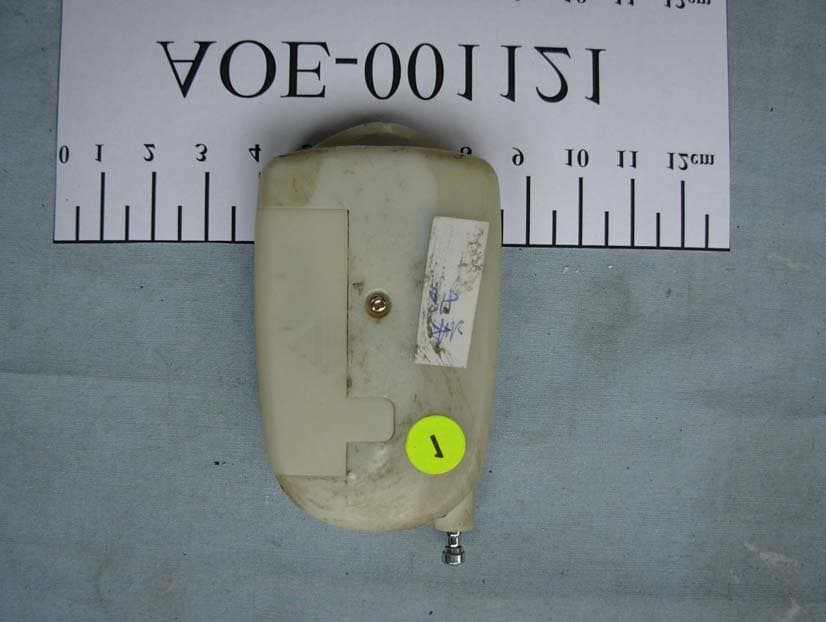
NYD5917
Aug 21, 2006REMOTE RAIN
Equipment Class
DSC - Part 15 Security/Remote Control Transmitter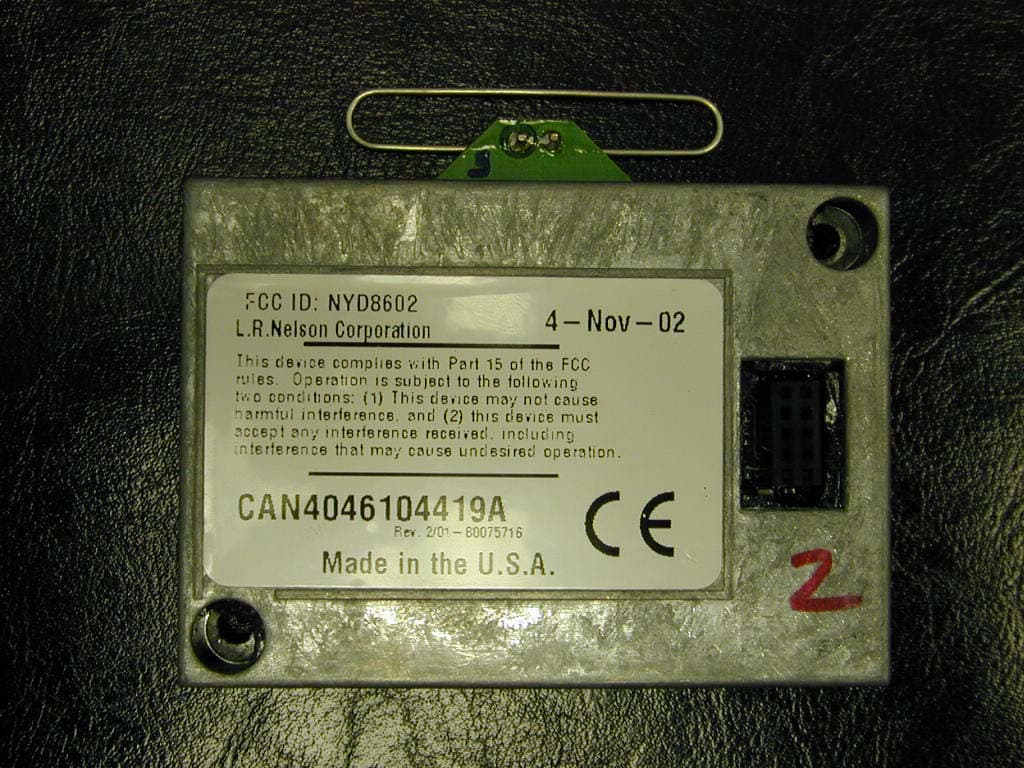
NYD8602
Feb 11, 2003Lawn Sprinkler Controller
Equipment Class
DSS - Part 15 Spread Spectrum Transmitter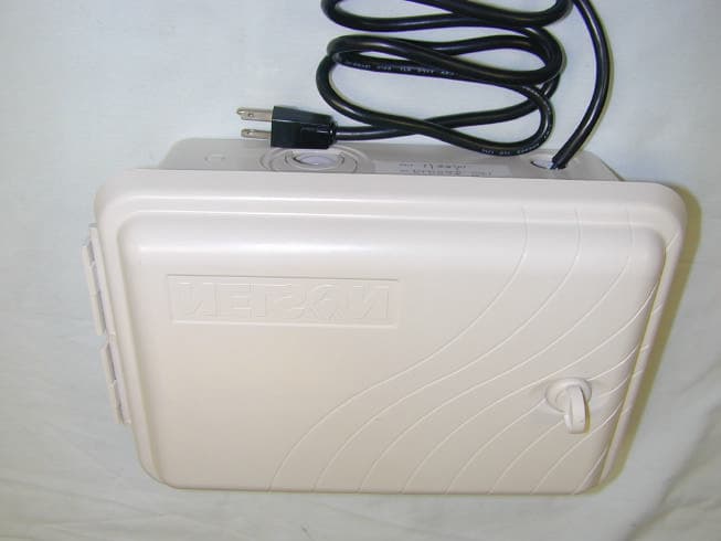
NYD86XX
Apr 11, 2001EZ Pro Electronic Irrigation Controller
Equipment Class
DSS - Part 15 Spread Spectrum Transmitter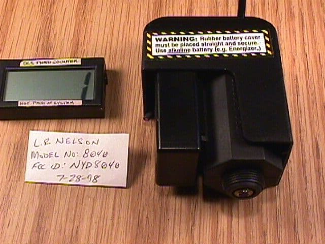
NYD8040
Sep 01, 1998Irrigation System Transceiver
Equipment Class
DXT - Part 15 Low Power Transceiver, Rx Verified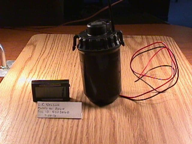
NYD8060
Sep 01, 1998Irrigation System Transceiver
Equipment Class
DXT - Part 15 Low Power Transceiver, Rx Verified