NYD86XXEZ Pro Electronic Irrigation Controller
L.R. Nelson Corporation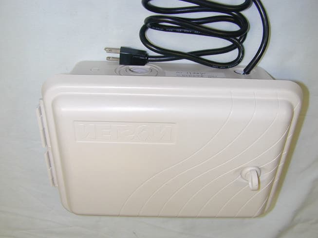
Click to zoom
Application Details
- Equipment Class
- DSS - Part 15 Spread Spectrum Transmitter
- Date of Grant
- Apr 11, 2001
- Application Purpose
- Original Equipment
- Date of Application
- Apr 11, 2001
- Equipment Note
- EZ Pro Electronic Irrigation Controller
- Frequency Range
- 2400.00000000 - 2438.50000000
- Company
- L.R. Nelson Corporation
- Country
- United States
Documents & Files
Document Text
Text extracted from the exhibit documents filed with the FCC. Open a document above to read the original.
Users Manual
Note to Pudik: This booklet is very similar to the existing SmartZone EZ instruction book 900-04862. It s look and layout should be similar. In fact much of the content is either identical or close. The size of the finished book needs to be 6 5/8 wide x 5 ½ tall (11” folded in half). This book will be English and Spanish. There is also planned a French –Italian version and a Portugese/German version Nelson EZ PRO™ Instructions Zone Chart 1_____________________ 13_____________________ 2_____________________ 14_____________________ 3_____________________ 15_____________________ 4_____________________ 16_____________________ 5_____________________ 17_____________________ 6_____________________ 18_____________________ 7_____________________ 19_____________________ 8_____________________ 20_____________________ 9_____________________ 21_____________________ 10____________________ 22_____________________ 11____________________ 23_____________________ 12____________________ 24_____________________ 90007357 Rev 9-00 Note to Pudik- We need 7/8 inch clearance for Zone chart from the bottom of line 12 and 24 to fold at bottom of page Nelson EZ Pro INSTALLATION AND PROGRAMMING GUIDE For EZ Pro Controller Models: 8604 8674 8604R 8674R 8606 8676 8606R 8676R 8608 8678 8608R 8678R 8612 8682 8612R 8682R 8616 8686 8616R 8686R 8520 8690 8620R 8690R 8624 8694 8624R 8694R Thank you for purchasing the EZ Pro TM electronic irrigation controller. This controller offers great features in the standard models and the added full function radio capability in the “R” models. The EZ Pro is so “EZ”, you’ll probably be able to install and program this feature-packed controller without instructions. However, before installing and programming the controller, we recommend you read these instructions carefully to take full advantage of all the EZ Pro TM has to offer. If you have questions, problems or comments on your new EZ Pro TM please call our Technical Services Department toll-free at 1-800-NELSON8. Leaders in Turf Irrigation Since 1911 NOTE: In our efforts to continually improve and update our products, features and specifications in this manual may change without notice. TABLE OF CONTENTS Features Installation Terminal Strip Connecting Master Valve or Pump-Start Relay Wiring the Transformer Connecting Rain/Moisture Sensor Connecting Battery & Resetting Controller Programming the EZ Pro Programming Overview Front Panel Layout Set Time of Day Set Current Day Set Today's Date Select Zones and Set Their Run Times Set Start Times Set % Water Budget Set % Water Budget by Month Set Master Valve or Pump Set Rain Delay Scheduling Set Water Days Scheduling Option Set Odd/Even Day Scheduling Option Set Interval Scheduling Option Program Review Turning the Controller Off Advanced Features Run A Zone Manually Run A Program Manually Run A 3 Minute Test (Syringe) Technical Data/Specifications Troubleshooting/Service FCC Rules Warranty FEATURES • Full function programming and manual remote control through radio transmission to EZ Command Remote Programmer (sold separately) • EZ Command Radio Module is available factory installed in “R” models or can be added on later • Nelson exclusive Select and Adjust TM programming • Non-volatile memory stores programs without AC power or batteries • Pump Start programmable by zone • Programmable Rain Delay to 99 days • Three independent programs • Four start times per program (12 total starts) • Stacking start times • Three scheduling options to suit the needs of plant material or to comply with watering restrictions (days of the week, 1-30 day interval, true odd / even ) • Leap year compatible-automatically includes Feb 29 th every four years • Water budget option reduces or increases watering 0-200 percent • Advanced water budget to set water budget for each month of the year • Three test cycles ( Manual with ManualAdvanceTM feature,Cycle, 3-minute test • Programmable run times from one minute to 9 hours 59 minutes • Poly-fuse self resetting circuit protection INSTALLATION INSTRUCTIONS The EZ Pro can be mounted indoors or outdoors. Find a location near a 120V wiring source (230/240V for 8674, 8676, 8678, 8682, 8686, 8690, and 8694 models). Install the EZ Pro near eye level if possible. Use the supplied template to mark and pre-drill pilot holes in the wall. The middle two hole guides in the EZ Pro are vertically aligned for mounting the controller to a stud. (See Template) Insert screws through the holes in the case and screw each into the corresponding pilot hole in the wall. NOTE: The front panel can be removed to aid in installation by removing the ribbon connector from the interconnect board and pulling the front panel off its hinges. "IMPORTANT NOTE For Radio models: To comply with FCC RF exposure compliance requirements, the following antenna installation and device operating configurations must be satisfied - The antenna used for this transmitter must be installed to provide a separation distance of at least 20 cm from all persons and must not be co-located or operating in conjunction with any other antenna or transmitter." Wiring the Transformer 120 VAC in United States, Canada and Mexico; 230 VAC in Europe and 240 VAC in Australia NOTE: Refer to and follow local codes if different from these instructions. CAUTION: Disconnect 120V (230/240V for 8674, 8676, 8678, 8682, 8686, 8690, and 8694 models) power source before wiring transformer. Complete all wiring and installation before connecting the transformer to power source. This will avoid accidental shorting which could damage the controller. Power supply cables and cords used for connections are to be a minimum of ordinary duty or greater duty. Live supply wires should be attached together adjacent to the terminal block. Low voltage output cables should be enclosed in conduit affixed to the controller with a suitable adapter. Remove the two screws and lift out the transformer cover to provide access to the internal transformer, bring 1…
Text truncated - open the document above for the full version.
Block Diagram
General Information on EZ Pro Controller Models 8674( R ) through 8694( R ). LR Nelson Confidential Aaron CoakleyPage 103/09/01 General Description: The EZ Pro is an AC Powered Irrigation Controller. The Primary input voltage is stepped down from line voltage (120VAC 60Hz Domestic, 230VAC 50Hz Export) to 24VAC (nominal), which then energizes the DC power supply and supplies power for the zones. The secondary is protected by a 1A Raychem® polyswitch (self-resetting current limiter). A microcontroller aboard the Front Panel Module controls a user interface which consists of 3 knobs and a 4 button keypad. The microcontroller keeps time using a 32kHz quartz oscillator and schedules when to turn on the appropriate zones according to what was programmed in on the user interface. The microcontroller also supplies limited diagnostic information as to the presence or absence of a fault on a zone and discontinues opearation of a faulty zone. The outputs consist of 4 through 24 zones which can only be turned on one at a time, along with a secondary output (called the Pump/Master Valve) which may or may not be turned on based upon user programming. 86xxR models incorporate a radio module, which allows for extension of the user interface to a handheld device. The radio consists of a Zinc encased 2.4GHz Spread Spectrum Radio. All of the Models use an identical enclosure, transformer, and control electronics. The only major differences between models is the number of available zones, the type of enclosure lock, inclusion of radio module, and physical size of interconnect. Instructions will be supplied appropriate to the language of the country in which the unit is sold. A circuit breaker device will protect the input of the transformer since the transformer must be wired to local codes. A statement will be added to the instructions stating that a disconnect device must be wired to the primary input of the controller. Table of Export Model Numbers and their differences Differences ModelDescription # ZonesLockInterconnect 8674 4 Zone Irrigation Controller4PlasticSmall 8676 6 Zone Irrigation Controller6PlasticSmall 8678 8 Zone Irrigation Controller8PlasticSmall 8682 12 Zone Irrigation Controller12Metal KeyLarge 8686 16 Zone Irrigation Controller16Metal KeyLarge 8690 20 Zone Irrigation Controller20Metal KeyLarge 8694 24 Zone Irrigation Controller24Metal KeyLarge 8674 4 Zone Irrigation Controller with Radio Module4PlasticSmall 8676 6 Zone Irrigation Controller with Radio Module6PlasticSmall 8678 8 Zone Irrigation Controller with Radio Module8PlasticSmall 8682 12 Zone Irrigation Controller with Radio Module12Metal KeyLarge 8686 16 Zone Irrigation Controller with Radio Module16Metal KeyLarge 8690 20 Zone Irrigation Controller with Radio Module20Metal KeyLarge 8694 24 Zone Irrigation Controller with Radio Module24Metal KeyLarge General Information Transformer Output Current1.25A PolySwitch protection1A Microprocessor primary oscillator32.768 kHz Microprocessor secondary oscillator4.194304 MHz Tested Enclosure is the same material that will be used in production GE Cycolac KJB General Information on EZ Pro Controller Models 8674( R ) through 8694( R ). LR Nelson Confidential Aaron CoakleyPage 203/09/01 1 Product Block Diagram Front Panel Interconnect User Interface: LCD Dials Pushbuttons Rain Sensor Interface Rain Sensor Peripheral Interface Radio Module (Optional) AC Detection Primary Power ProtectionTransformer Pre-regulation and Filtering Monitor circuit Micro- Controller EEPROM Provision for direct Earth ground SolenoidSolenoidSolenoid Zone Interface Zone Drivers Current Detection Lightning Protection Regulation, Protect, Filter Secondary Power General Information on EZ Pro Controller Models 8674( R ) through 8694( R ). LR Nelson Confidential Aaron CoakleyPage 303/09/01 System Overview The addition of the EZ Command and radio modules to the system allows the user to have a mirror of the interface at the front panel to the user carrying the Command. The LCD display on the command mirrors the display on the controller, and the Command periodically sends the dial position and any key-presses. The EZ Pro and Command communicate to the radio modules using a custom serial protocol. Only data conforming to the protocol will be passed between the radios. Block diagram of a basic EZ Pro and Command system EZ Pro Controller Front Panel Interconnect Radio Module AC Solenoids in buried valve box EZ Command Radio Module Microcontroller User Interface ‘C’ batteries Boost
Cover Letter(s)
FCC ID: NYD86XX Response to TCB questions -----Original Message----- From: Certification Manager [SMTP:[email protected] ] Sent: Monday, April 02, 2001 3:04 PM To: Davida Hanson Cc: David Light Subject: FCC ID: NYD86XX Hi Davida, We have identified the following issues during our review of the application: 1. The 731 form and part of the test report indicates that this is an 88mW unit. The only test data we can find is in the radiated measurement section since this has a non-detachable antenna. It measures 22mW. Please explain the 88mW rating. Response - The form was filled out incorrectly using data from the other EZ Pro product. The rating should be 22 mW. Do we need to submit a new form or can you make changes to the one you have? 2. On page 15 of the test report, when the slave transmitter is hopping to the next channel while searching for a master unit, is it following a pseudo-random sequence? Response - Yes, both the master and slave are always following a pseudo-random sequence. 3. Please tell us the receiver input bandwidth for this transmitter. Response - 80 kHz 4. Please provide data responsive to 15.31(e). Response - Voltage was varied from 98 Vac to 132 Vac and verified as having no affect on Rf power output. 5. Please confirm that the LISN used was a 50 Ohm/50uH model. Response - Yes, the Schwarzbeck Model 8120 LISN is 50 ohm/50 uH 6. Please tell us the estimated antenna gain. Response - 0 dBi 7. For the radiated emissions table, please explain how compliance is shown with the 74dBuV/m peak emissions limit. Usually we see peak and average measurement data. Please provide peak measurement data. See 15.35 (b). Response - Sorry Barry, the data sheet is marked incorrectly. Measurements were taken using Peak detection with Average limits applied. Attached is corrected data sheet. <<restricted band emissions base2.xls> 8. We need an MPE calculation to prove that the device is safe at 20cm. Response - MPE calculation attached <<MPEPrediction.pdf> 9. The users manual does not contain any RF exposure warning statements. For a mobile unit the appropriate wording is - "IMPORTANT NOTE: To comply with FCC RF exposure compliance requirements, the following antenna installation and device operating configurations must be satisfied - The antenna used for this transmitter must be installed to provide a separation distance of at least 20 cm from all persons and must not be co-located or operating in conjunction with any other antenna or transmitter." Response - The MPE calculation is above. Also, the device is a base unit and is to be permanently mounted to a wall and therefore should not need the statement. TCB note – it was later agreed the unit would be classified as mobile. 10. Please arrange for the attached certification agreement to be completed and signed. Best regards Barry C. Quinlan Certification & Telecom Manager -------------------------------------------------------------------------- ----- Curtis-Straus LLC Voice: 978.486.8880 x270 527 Great Road Fax: 978.486.8828 Littleton, MA 01460 <http://www.curtis-straus.com > -------------------------------------------------------------------------- ------ << File: Agreement.PDF >>
Cover Letter(s)
REQUEST FOR CONFIDENTIALITY L.R. Nelson Corporation requests confidentiality with regard to the following documents in the filing for equipment approval identified by FCC ID. No. CFD825FBCP-201. (1) Schematic diagrams contained in electronic files identified as: ♦ Nelson 8600 Command.pdf ♦ Nelson 86XX EZ Pro Front Panel.pdf ♦ Nelson 86XX EZ Pro Interconnect.pdf ♦ Nelson 86xx Radio.pdf It is the opinion of L.R. Nelson Corporation, disclosure of this information would result in significant loss of revenue. This information should be kept confidential for 5 calendar years. L.R. Nelson Corporation One Sprinkler Lane Peoria, IL 61615 08MAR01 NOTE: Only information that is not accessible to the general public may be held confidential. Generally internal and external photos cannot be held confidentiality. The exception would be if the PC board is potted.
External Photos
FCC ID: NYD86XX External photos
ID Label/Location Info
This device complies with Part 15 of the FCC rules. Operation is subject to the following two conditions: (1) This device may not cause harmful interference, and (2) this device must accept any interference received, including interference that may cause undesired operation. Made in U.S.A.Rev 1/01-800xxxxx FCC ID: NYD86XX L.R. Nelson Corporation Bottom side of EZ Pro Controller 1.5 in/31.8 mm 2.5 in/63.5 mm NELSON
ID Label/Location Info
label data sheet (1728x2138x2 tiff) label data sheet (1728x2138x2 tiff) [2] label data sheet (1728x2134x2 tiff) [3]
Internal Photos
FCC ID: NYD86XX Internal photos
Operational Description
General Information on EZ Pro Controller Models 8674( R ) through 8694( R ). LR Nelson Confidential Aaron CoakleyPage 103/09/01 General Description: The EZ Pro is an AC Powered Irrigation Controller. The Primary input voltage is stepped down from line voltage (120VAC 60Hz Domestic, 230VAC 50Hz Export) to 24VAC (nominal), which then energizes the DC power supply and supplies power for the zones. The secondary is protected by a 1A Raychem® polyswitch (self-resetting current limiter). A microcontroller aboard the Front Panel Module controls a user interface which consists of 3 knobs and a 4 button keypad. The microcontroller keeps time using a 32kHz quartz oscillator and schedules when to turn on the appropriate zones according to what was programmed in on the user interface. The microcontroller also supplies limited diagnostic information as to the presence or absence of a fault on a zone and discontinues opearation of a faulty zone. The outputs consist of 4 through 24 zones which can only be turned on one at a time, along with a secondary output (called the Pump/Master Valve) which may or may not be turned on based upon user programming. 86xxR models incorporate a radio module, which allows for extension of the user interface to a handheld device. The radio consists of a Zinc encased 2.4GHz Spread Spectrum Radio. All of the Models use an identical enclosure, transformer, and control electronics. The only major differences between models is the number of available zones, the type of enclosure lock, inclusion of radio module, and physical size of interconnect. Instructions will be supplied appropriate to the language of the country in which the unit is sold. A circuit breaker device will protect the input of the transformer since the transformer must be wired to local codes. A statement will be added to the instructions stating that a disconnect device must be wired to the primary input of the controller. Table of Export Model Numbers and their differences Differences ModelDescription # ZonesLockInterconnect 8674 4 Zone Irrigation Controller4PlasticSmall 8676 6 Zone Irrigation Controller6PlasticSmall 8678 8 Zone Irrigation Controller8PlasticSmall 8682 12 Zone Irrigation Controller12Metal KeyLarge 8686 16 Zone Irrigation Controller16Metal KeyLarge 8690 20 Zone Irrigation Controller20Metal KeyLarge 8694 24 Zone Irrigation Controller24Metal KeyLarge 8674 4 Zone Irrigation Controller with Radio Module4PlasticSmall 8676 6 Zone Irrigation Controller with Radio Module6PlasticSmall 8678 8 Zone Irrigation Controller with Radio Module8PlasticSmall 8682 12 Zone Irrigation Controller with Radio Module12Metal KeyLarge 8686 16 Zone Irrigation Controller with Radio Module16Metal KeyLarge 8690 20 Zone Irrigation Controller with Radio Module20Metal KeyLarge 8694 24 Zone Irrigation Controller with Radio Module24Metal KeyLarge General Information Transformer Output Current1.25A PolySwitch protection1A Microprocessor primary oscillator32.768 kHz Microprocessor secondary oscillator4.194304 MHz Tested Enclosure is the same material that will be used in production GE Cycolac KJB General Information on EZ Pro Controller Models 8674( R ) through 8694( R ). LR Nelson Confidential Aaron CoakleyPage 203/09/01 1 Product Block Diagram Front Panel Interconnect User Interface: LCD Dials Pushbuttons Rain Sensor Interface Rain Sensor Peripheral Interface Radio Module (Optional) AC Detection Primary Power ProtectionTransformer Pre-regulation and Filtering Monitor circuit Micro- Controller EEPROM Provision for direct Earth ground SolenoidSolenoidSolenoid Zone Interface Zone Drivers Current Detection Lightning Protection Regulation, Protect, Filter Secondary Power General Information on EZ Pro Controller Models 8674( R ) through 8694( R ). LR Nelson Confidential Aaron CoakleyPage 303/09/01 System Overview The addition of the EZ Command and radio modules to the system allows the user to have a mirror of the interface at the front panel to the user carrying the Command. The LCD display on the command mirrors the display on the controller, and the Command periodically sends the dial position and any key-presses. The EZ Pro and Command communicate to the radio modules using a custom serial protocol. Only data conforming to the protocol will be passed between the radios. Block diagram of a basic EZ Pro and Command system EZ Pro Controller Front Panel Interconnect Radio Module AC Solenoids in buried valve box EZ Command Radio Module Microcontroller User Interface ‘C’ batteries Boost
RF Exposure Info
Prediction of MPE limit at a given distance Equation from page 18 of OET Bulletin 65, Edition 97-01 where:S = power density P = power input to the antenna G = power gain of the antenna in the direction of interest relative to an isotropic radiator R = distance to the center of radiation of the antenna Maximum peak output power at antenna input terminal:13.40(dBm) Maximum peak output power at antenna input terminal:21.87762(mW) Antenna gain(typical):0(dBi) Maximum antenna gain:1(numeric) Prediction distance:2(cm) Prediction frequency:2400(MHz) MPE limit for uncontrolled exposure at prediction frequency:1(mW/cm^2) Power density at prediction frequency:0.435241(mW/cm^2) Maximum allowable antenna gain:3.612699(dBi) 2 4R PG S π =
Test Report
Nemko Test Report: 0L0528RUS2 Applicant: L.R. Nelson Corp. One Sprinkler Lane Peoria, IL 61615-9544 Equipment Under Test: EZ Pro Controller (E.U.T.) FCC ID: NYD86XX In Accordance With: FCC Part 15, Subpart C, 15.247 Frequency Hopping Transmitters Tested By: Nemko Dallas Inc. 802 N. Kealy Lewisville, Texas 75057-3136 Authorized By: Tom Tidwell, RF Group Manager Date: Total Number of Pages: 56 Nemko Dallas FCC PART 15, SUBPART C FREQUENCY HOPPING SPREAD SPECTRUM TRANSMITTER EQUIPMENT: EZ Pro Controller FCC ID: PROJECT NO.: 0L0528RUS2 Page 2 of 56 Table of Contents Section 1. Summary of Test Results 3 Section 2. Equipment Under Test (E.U.T.) 5 Section 3. Powerline Conducted Emissions 8 Section 4. Channel Separation 9 Section 5. Pseudorandom Hopping Algorithm 13 Section 6. Time of Occupancy 15 Section 7. Occupied Bandwidth 31 Section 8. Peak Power Output 34 Section 9. Spurious Emissions (Antenna Conducted) 38 Section 10. Spurious Emissions (Radiated) 39 Section 11. Test Equipment List 43 ANNEX A - TEST DETAILS 44 ANNEX B - TEST DIAGRAMS 54 Nemko Dallas FCC PART 15, SUBPART C FREQUENCY HOPPING SPREAD SPECTRUM TRANSMITTER EQUIPMENT: EZ Pro Controller FCC ID: PROJECT NO.: 0L0528RUS2 Page 3 of 56 Section 1. Summary of Test Results Manufacturer: L.R. Nelson Corp. Model No.: EZ Pro Controller Serial No.: None General: All measurements are traceable to national standards. These tests were conducted on a sample of the equipment for the purpose of demonstrating compliance with Part 15, Subpart C, Paragraph 15.247 for Frequency Hopping Spread Spectrum devices. Radiated tests were conducted is accordance with ANSI C63.4-1992. Radiated emissions are made on an open area test site. A description of the test facility is on file with the FCC. New Submission Production Unit Class II Permissive Change Pre-Production Unit Family Listing THIS TEST REPORT RELATES ONLY TO THE ITEM(S) TESTED. THE FOLLOWING DEVIATIONS FROM, ADDITIONS TO, OR EXCLUSIONS FROM THE TEST SPECIFICATIONS HAVE BEEN MADE. See “ Summary of Test Data”. NVLAP LAB CODE: 100426-0 TESTED BY: _____________________________________ DATE: ___________________ Nemko Dallas Inc. authorizes the above named company to reproduce this report provided it is reproduced in its entirety and for use by the company’s employees only. Any use which a third party makes of this report, or any reliance on or decisions to be made based on it, are the responsibility of such third parties. Nemko Dallas Inc. accepts no responsibility for damages, if any, suffered by any third party as a result of decisions made or actions based on this report. This report applies only to the items tested. Nemko Dallas FCC PART 15, SUBPART C FREQUENCY HOPPING SPREAD SPECTRUM TRANSMITTER EQUIPMENT: EZ Pro Controller FCC ID: PROJECT NO.: 0L0528RUS2 Page 4 of 56 Summary Of Test Data NAME OF TEST PARA. NO. SPEC. MEAS. RESULT Powerline Conducted Emissions 15.207(a) 48 dBμV 23.05 dBuV Complies Channel Separation 15.247(a)(1) Greater of 25 kHz or 20 dB Bandwidth 85 kHz Complies Pseudorandom Hopping Algorithm 15.247(a)(1) Customer Supplied Customer Supplied Customer Supplied Time of Occupancy 15.247(a)(1)(ii) ≤ 0.4 sec in 30 sec 0.3 sec in 30 sec. Complies 20 dB Occupied Bandwidth 15.247(a)(1) ≤ 1 MHz Complies Peak Power Output 15.247(b) 4 Watts EIRP 88 mW Complies Spurious Emissions (Antenna Conducted) 15.247(c) -20 dBc N/A N/A Spurious Emissions (Radiated) 15.247(c) Table 15.209(a) See Data Complies Footnotes: The device does not have a detachable antenna. Nemko Dallas FCC PART 15, SUBPART C FREQUENCY HOPPING SPREAD SPECTRUM TRANSMITTER EQUIPMENT: EZ Pro Controller FCC ID: PROJECT NO.: 0L0528RUS2 Page 5 of 56 Section 2. Equipment Under Test (E.U.T.) General Equipment Information Frequency Band: 902 – 928 MHz 2400 – 2483.5 MHz Number of Channels: 75 Channel Spacing: 85 kHz User Frequency Adjustment: Software controlled Nemko Dallas FCC PART 15, SUBPART C FREQUENCY HOPPING SPREAD SPECTRUM TRANSMITTER EQUIPMENT: EZ Pro Controller FCC ID: PROJECT NO.: 0L0528RUS2 Page 6 of 56 Description of Modification for Modification Filing Family List Rational Nemko Dallas FCC PART 15, SUBPART C FREQUENCY HOPPING SPREAD SPECTRUM TRANSMITTER EQUIPMENT: EZ Pro Controller FCC ID: PROJECT NO.: 0L0528RUS2 Page 7 of 56 Theory of Operation The EZ Pro is an AC Powered Irrigation Controller. The Primary input voltage is stepped down from line voltage (120VAC 60Hz Domestic, 230VAC 50Hz Export) to 24VAC (nominal), which then energizes the DC power supply and supplies power for the zones. The secondary is protected by a 1A Raychem® polyswitch (self-resetting current limiter). A microcontroller aboard the Front Panel Module controls a user interface which consists of 3 knobs and a 4 button keypad. The microcontroller keeps time using a 32kHz quartz oscillator and schedules when to turn on the appropriate zones according to what was programmed in on the user interface. The microcontroller also supplies limited diagnostic information as to the presence or absence of a fault on a zone and discontinues opearation of a faulty zone. The outputs consist of 4 through 24 zones which can only be turned on one at a time, along with a secondary output (called the Pump/Master Valve) which may or may not be turned on based upon user programming. 86xxR models incorporate a radio module, which allows for extension of the user interface to a handheld device. The radio consists of a Zinc encased 2.4GHz Spread Spectrum Radio. All of the Models use an identical enclosure, transformer, and control electronics. The only major differences between models is the number of available zones, the type of enclosure lock, inclusion of radio module, and physical size of interconnect. Instructions will be supplied appropriate to the language of the country in which the unit is sold. System Diagram Nemko Dallas FCC PART 15, SUBPART C FREQUENCY HOPPING SPREAD SPECTRUM TRANSMITTER EQUIPMENT: EZ Pro Controller FCC ID: PROJECT NO.: 0L0528RUS2 Page 8 of 56 Section…
Text truncated - open the document above for the full version.
Test Setup Photos
Nemko Dallas FCC PART 15, SUBPART C FREQUENCY HOPPING SPREAD SPECTRUM TRANSMITTER EQUIPMENT: EZ Pro Controller FCC ID: PROJECT NO.: 0L0528RUS2 Page 11 of 56 Photographs - Powerline Conducted Emissions Front Side Nemko Dallas FCC PART 15, SUBPART C FREQUENCY HOPPING SPREAD SPECTRUM TRANSMITTER EQUIPMENT: EZ Pro Controller FCC ID: PROJECT NO.: 0L0528RUS2 Page 42 of 56 Radiated Photographs (Worst Case Configuration) FRONT VIEW REAR VIEW
Contact Information
Applicant
David A. Paul(Electronics Engineering Manager)
309-690-2722
Test Firm
Nemko Dallas, Inc.Michael Cantwell
Technical Specifications
| # | Rule Parts | Frequency Range | Power Output |
|---|---|---|---|
| 1 | 15C | 2.40 GHz - 2.44 GHz | 22.00 mW |
Other Applications from L.R. Nelson Corporation
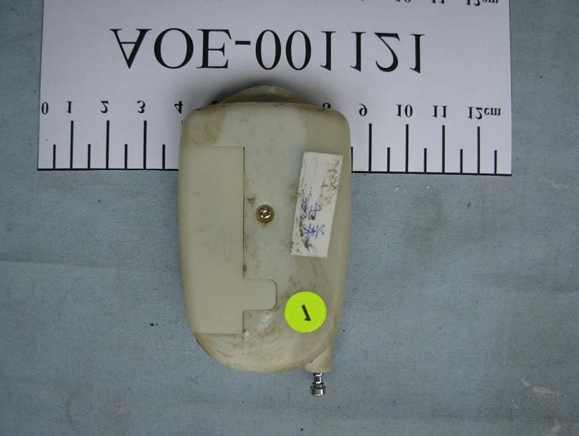
NYD5917
Aug 21, 2006REMOTE RAIN
Equipment Class
DSC - Part 15 Security/Remote Control Transmitter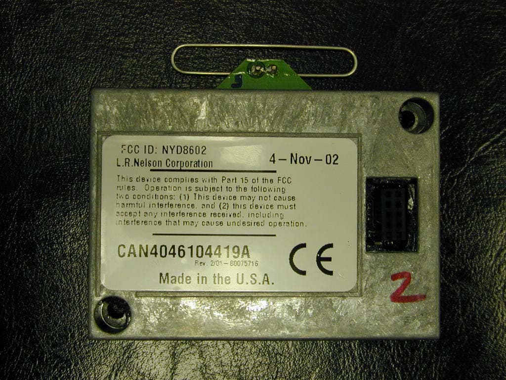
NYD8602
Feb 11, 2003Lawn Sprinkler Controller
Equipment Class
DSS - Part 15 Spread Spectrum Transmitter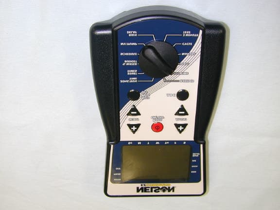
NYD8600
Apr 24, 2001EZ Pro Command Irrigation Controller
Equipment Class
DSS - Part 15 Spread Spectrum Transmitter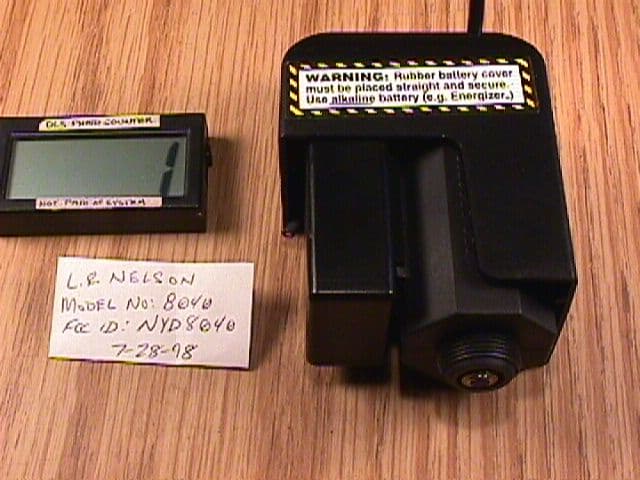
NYD8040
Sep 01, 1998Irrigation System Transceiver
Equipment Class
DXT - Part 15 Low Power Transceiver, Rx Verified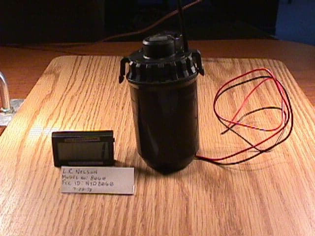
NYD8060
Sep 01, 1998Irrigation System Transceiver
Equipment Class
DXT - Part 15 Low Power Transceiver, Rx Verified