NZI-11705920Rugged Smart Phone
TRIMBLE EUROPE BV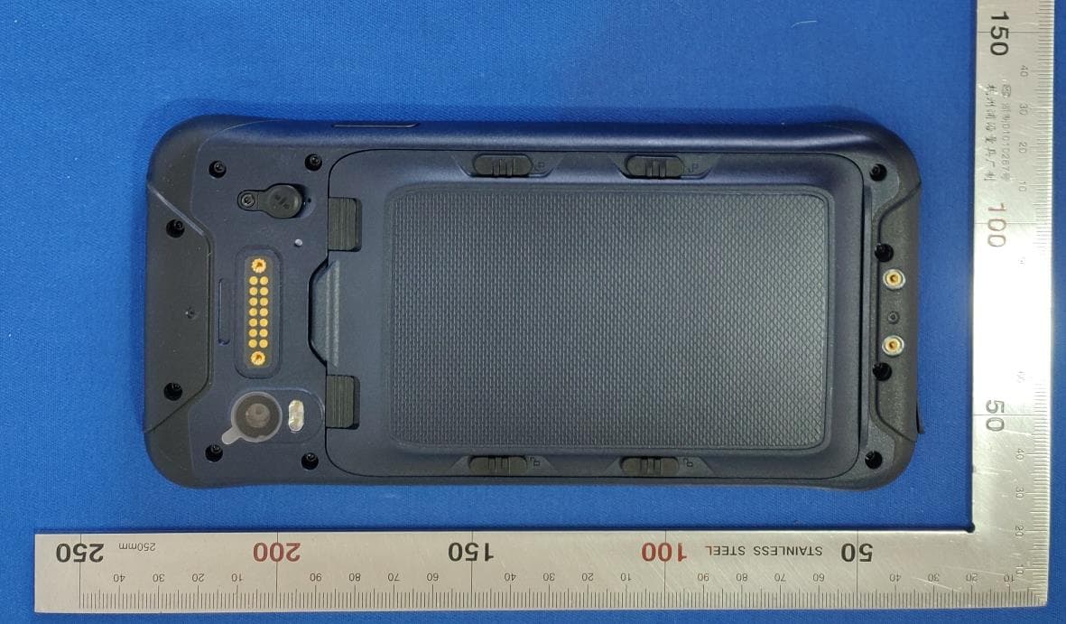
Click to zoom
Application Details
- Equipment Class
- NII - Unlicensed National Information Infrastructure TX
- Date of Grant
- May 09, 2021
- Application Purpose
- Original Equipment
- Date of Application
- May 06, 2021
- Equipment Note
- Rugged Smart Phone
- Frequency Range
- 5745.00000000 - 5825.00000000
- Company
- TRIMBLE EUROPE BV
- Country
- Netherlands
Documents & Files
Document Text
Text extracted from the exhibit documents filed with the FCC. Open a document above to read the original.
Users Manual
Quick Start Guide TDC600 Microphone Extended Function Key 2 Extended Function Key 3 Increase Volume Decrease Volume Power Key Extended Function Key 1 Custom side button Speaker Front Camera Earpiece Light Sensor TYPE-C interfaceHandstrap fixing holes Rear camera LED Flash Docking Contact Pins Battery cover lock Battery cover lockBattery cover lock Lanyard fixing External antenna port Handstrap fixing holes Tear off when using CAM Lens protective film NFC 1. Battery Charging •Charge with travel charger Insert the small plug end of the USB data cable into the TYPE-C port of the device, insert the large plug end of the USB data cable into the travel charger plug, and then insert the travel charger plug into a power outlet to charge. • Charge with USB data cable Insert the small plug end of the USB data cable into the TYPE-C port of the device, insert the large plug end into the USB port of the computer to charge. Note: During normal charging, the home screen status bar will display the charging icon when screen is on. When the charging is completed, the home screen status bar will display the full battery icon when screen is on. 2. Install SIM card, memory card, battery Power o ff the device before installing or removing the SIM card, MicroSD card or battery. Flip the device to its rear, follow the directions shown in Figure 1 and push the back cover lock to the open position, and remove the battery cover. Install the SIM card and MicroSD card according to the battery compartment label instructions, as shown in Figure 2. Figure 1 • Face the SIM card metal contacts downwards and push into the slot. Take note on the direc- tion of the notched corner. • Face the MicroSD card metal contacts downwards and push into the slot. Take note on the direction of the notched corner. • Align the contacts of the battery with the terminals of the battery compartment and put in the battery gently. • After the battery is installed, replace the battery compartment cover and push the back cover lock to locked position to secure the battery compartment cover. Figure 2 SIM2SIM1Micro SD Figure 1Figure 2 Figure 3 Figure 2 Handstrap 3. Turning the device on and off To turn on the device, firmly press and hold the bottom right Power Buttonuntil the boot screen appears. To turn off the device, firmly press and hold the Power Button to display the options menu. Select the Power o ff option to shutdown. With the device turned on, press the Power Buttonto turn off the screen and go into sleep mode; Press the Power Button again to wake the device, swipe upwards on the screen to unlock; If the device has been idle for a period of time, the screen will automatical- ly turn o ff and go into sleep mode. 4. Home screen operation From the home screen, you can view the device status and access the applications. The home screen can have multiple panels; Swipe up on the screen to view each panel. At the top of the home screen is the status bar , which contains the notification area, the status area and the display area; the shortcut panel is at the bottom. •Using the notification panel When new notification icons appear in the notification area of the status bar, hold the status bar and drag down to open the notification panel; To hide the panel, drag the bottom border of the panel upwards. •Customize the shortcut panel You can customize the shortcuts at the bottom of the home screen by adding or removing “Shortcut Icons”. To remove the “Shortcut icon”, press and hold the “Shortcut icon” and drag it to the “Delete icon”. To add a “Shortcut icon”, press and hold the icon on the home screen and drag it to the Shortcut panel. •Using applications Slide the screen up to see all the included applications.Touch the [Home button] below the screen to close it and return to the home screen. Figure 3 •Expanding the home screen Swipe your finger horizontally on the home screen to expand to the up of the home screen. - Adding an icon on the home screen Press and hold any application or widget icon and drag it to an empty area on the home screen. - Moving icons on the home screen Press and hold the icon on the home screen and drag the icon to the desired location on the screen. - Removing icons on the home screen Press and hold the home screen icon and drag the icon to the "Delete" icon until the icon turns red. •Create folder - On the home screen, folders are automatically formed when you drag an icon onto another icon. - Touch the new folder on the screen to open it. Click on the folder’s label to rename it. •Changing the home screen wallpaper Press and hold a blank area on the home screen or touch the [Menu button] → "Wallpaper" to change the home screen wallpaper by selecting options such as wallpaper, live wallpa- per, gallery, etc. 5. Connecting to a computer Use the USB data cable to connect the device to the computer, pull down the top status bar and you can see the message "Android System . Charging this device via USB" in the notification area. Clicking on Tap for more options will bring up USB Preferences with 5 options "File Transfer", "USB tethering", "MIDI", "PTP", "No data transfer", which can be selected according to your needs. 7. Installation and management of applications 1. The very first time a microSD card is present when the device is turned on, You'll have to set it up as portable storage. 2. If you need to Rename or Eject or Format as portable or Migrate data the microsd card when the device is turned on, slide the screen tothe up " Settings-Storage-SD card→ ,, which can be selected according to your needs. Users can enter the applications store to download and install related application programs. Slide the screen up → "Settings", select " Apps & notifications" →"App info" to Select the application that you want to manage and apply the required actions. 6. SD card Settings 8. Using Beidou/GPS/GLONASS/GALILEO positioning function 9. Camera and videos Slide the screen up→ "Camera", to turn on the camera, the screen orien…
Text truncated - open the document above for the full version.
Cover Letter(s)
SCS-F019: Confidentiality Request Letter Page 1 of 2 Rev 7.0 775 Montague Expressway Milpitas, CA 95035 Tel: 408-526-1188 Fax: 408-526-1088 Email: [email protected] Website: https://www.cps.bureauveritas.com/ Confidentiality Request Letter Reason for Amendment (current / obsolete) Revision History Approved Date From To Initial Release (obsolete) 1.0 1.0 Nov-14-2006 Adding CFR 2.459 (obsolete) 1.0 2.0 August – 11 - 2008 Updated company template & Added text box (obsolete) 2.0 3.0 Jan-31-2012 Added IC confidentiality letter form (obsolete) 3.0 4.0 March-26-2015 Corrections to STC form. Added reference to KDB (obsolete) 4.0 5.0 Nov-19-2015 Updated company logo (current) 5.0 6.0 Jun-26-2019 Updated References and Contact Info 6.0 7.0 Aug-30-2020 SCS-F019: Confidentiality Request Letter Page 2 of 2 Rev 7.0 Trimble Europe BV Apr.-02-2021 To: Federal Communications Commission Authorization and Evaluation Division 7435 Oakland Mills Road Columbia, MD 21046-1609 Cc: Bureau Veritas Consumer Products Services Inc. 775 Montague Expressway Milpitas, CA 95035 Subject: Confidentiality Request for FCC ID: NZI-11705920 Pursuant to CFR 47 sections 0.457 and 0.459, we respectfully request permanent confidential treatment of the following Exhibits accompanying this application be held confidential: Type of Confidentiality Requested Exhibit Short Term Permanent Block Diagram Short Term External Photos Short Term Permanent i Internal Photos Short Term Permanent Operational Description/ Theory of Operation Short Term Permanent Parts List Short Term Permanent Tune-Up Procedure Short Term Permanent Schematics Short Term Test Setup Photos Short Term Permanent i User’s Manual Permanent FCC Software Security Requirements for UNII devices Rev 2.1 The above materials contain trade secrets and proprietary information not customarily released to the public. The public disclosure of these materials may be harmful to the applicant and provide unjustified benefits to its competitors. Permanent Confidentiality: The applicant requests the exhibits listed above as permanently confidential be permanently withheld from public review due to materials that contain trade secrets and proprietary information not customarily released to the public. Short-Term Confidentiality: To avoid premature release of sensitive information prior to marketing or release of the product to the public, the applicant requests the following documents contained in this certification application be temporarily withheld from public disclosure for an initial period of 45 or 180 days; or for a specified date of not to exceed 180 days from the Grant Date The applicant understands that disclosure of this application and all accompanying documentation will not be made before the date of the Grant for this application. Sincerely, Signature: Name / title Joel Hamberg Magnusson / Regulatory Compliance Engineer Contact information / address: Trimble Europe BV. Industrieweg 187a, 5683 CC Best, Netherlands i Permanent confidentiality may be requested in accordance with FCC KDB 726920
Cover Letter(s)
DECLARATION OF MODEL DIFFERENCE Date: 2021-03-19 To Whom It May Concern: Hereby, We, Trimble Europe BV., hereby declare that the information as below is complete and accurate. Model No.: TDC600_2 MobileMapper60_2 Product Name: Rugged Smart Phone Enclosure Color: Yellow and Black Blue and Black Brand Name: Trimble Spectra Geospatial Software version TDC600_2.53.10.14 MM60_2.53.10.05 Model differences: MobileMapper60;TDC600 are identical with the same schematics, PCB layout, structure and components. They are the same product, just have the different model name and Brand Name and different colors and different software version. We, Trimble Europe BV., hereby declare that the Brand Name Trimble and Spectra Geospatial are our own self-owned brands. Please contact me if there is need for any additional clarification or information. Sincerely, Signature: Name/Title: Joel Hamberg Magnusson / Regulatory Compliance Engineer Company: Trimble Europe BV. E-mail: [email protected]
External Photos
Document No: SHE2010017-02 Page 1 of 3 E7167K(TDC600_2) External photo Front Back Document No: SHE2010017-02 Page 2 of 3 Left side Right side Document No: SHE2010017-02 Page 3 of 3 Top Bottom Document No: SHE2010017-02 Page 1 of 3 E7167KB (MobileMapper60_2) External photo Front Back Document No: SHE2010017-02 Page 2 of 3 Left side Right side Document No: SHE2010017-02 Page 3 of 3 Top Bottom
ID Label/Location Info
Document No: SHE20100017-02 Page 1 of 1 Label Location
Internal Photos
Document No: SHE20100017-02 Page 1 of 5 E7167KB ( MM60_2) Internal photo Internal 1 Internal 2 WIFI/BT antenna DIV antenna Main antenna NFC antenna Document No: SHE20100017-02 Page 2 of 5 Internal 3 Internal 4 Document No: SHE20100017-02 Page 3 of 5 Internal 5 Internal 6 2G/3G/4G chip Document No: SHE20100017-02 Page 4 of 5 Internal 7 Internal 8 GPS antenna Wifi /BTChip Document No: SHE20100017-02 Page 5 of 5 Internal 9 Internal 10 Wifi /BT Chip
RF Exposure Info
TEST REPORT Report No.: SHE20100017-02SE Date: 2021-03-15 Page 1 of 116 Applicant : Trimble Europe BV. Address of Applicant : Industrieweg 187a, 5683 CC Best, Netherlands Product Name : Rugged Smart Phone Model No. : TDC600_2, MobileMapper60_2 Sample No. : E20100017-01 #04 E20100017-01 #07 Standards : FCC 47 CFR § 2.1093 IEEE Std1528-2013 ANSI C95.1-2005 RSS-102 Issue 5 March 2015 Date of Receipt : 2021-01-26 Date of Test : 2021-02-18 ~ 2021-03-15 Date of Issue : 2021-03-15 Remark: This report details the results of the testing carried out on one sample, the results contained in this report do not relate to other samples of the same product. The manufacturer should ensure that all products in series production are in conformity with the product sample detailed in this report. Prepared by: Reviewed by: Approved by: (Oliver Xiang) (Jennifer Zhou) (Authorized signatory: Guoyou Chi) TEST REPORT Report No.: SHE20100017-02SE Date: 2021-03-15 Page 2 of 116 Contents 1 GENERAL INFORMATION ................................................................................................................................................... 4 1.1 TESTING LABORATORY ............................................................................................................................................................... 4 1.2 DETAILS OF APPLICATION .......................................................................................................................................................... 4 1.3 DETAILS OF EUT ........................................................................................................................................................................ 4 1.4 IDENTIFICATION OF AUXILIARY EQUIPMENT ............................................................................................................................... 5 1.5 THE HIGHEST REPORTED SAR VALUES ................................................................................................................................... 5 1.6 TEST METHODOLOGY ................................................................................................................................................................. 6 1.7 SAR LIMITS ................................................................................................................................................................................ 6 2 TEST ENVIRONMENT ........................................................................................................................................................... 8 2.1 ENVIRONMENTAL CONDITIONS ................................................................................................................................................... 8 2.2 EQUIPMENT LIST ........................................................................................................................................................................ 8 2.3 MEASUREMENT UNCERTAINTY................................................................................................................................................... 9 3 SAR MEASUREMENT SYSTEM ........................................................................................................................................ 11 3.1 DASY6 MEASUREMENT SERVER ............................................................................................................................................ 12 3.2 DATA ACQUISITION ELECTRONICS ........................................................................................................................................... 12 3.3 EX3DV4 E-FIELD PROBE ........................................................................................................................................................ 12 3.4 SAM PHANTOM ........................................................................................................................................................................ 13 3.5 DEVICE HOLDER FOR SAM TWIN PHANTOM ........................................................................................................................... 14 4 SAR MEASUREMENT PROCEDURES ............................................................................................................................ 15 4.1 POWER REFERENCE MEASUREMENT ...................................................................................................................................... 15 4.2 AREA SCAN PROCEDURES ....................................................................................................................................................... 15 4.3 ZOOM SCAN PROCEDURES ...................................................................................................................................................... 15 4.4 POWER DRIFT MEASUREMENT .................................................................................................................................................. 16 4.5 POSITION OF THE WIRELESS DEVICE IN RELATION TO THE PHANTOM ...................................................................................... 16 4.6 DEFINITION FOR TOUCH AND TILT ............................................................................................................................................ 17 4.7 DEFINITION FOR BODY-WORN ACCESSORY CONFIGURATIONS .............................................................................................. 19 4.8 DEFINITION FOR WIRELESS ROUTER CONFIGURATIONS ......................................................................................................... 19 4.9 DIELECTRIC PROPERTY MEASUREMENTS ............................................................................................................................... 19 4.10 SAR SYSTEM VERIFICATION ....................................................................................................…
Text truncated - open the document above for the full version.
RF Exposure Info
TEST REPORT Report No.: SHE20100017-02SE Date: 2021-03-15 Page 61 of 116 802.11ac(VHT20) Front Side 10 36 5180 -0.17 0.088 10.64 11.00 1.09 84.3 1.19 0.110 32# Back Side 10 36 5180 -0.11 0.061 10.64 11.00 1.09 84.3 1.19 0.066 Left Side 10 36 5180 0.13 0.083 10.64 11.00 1.09 84.3 1.19 0.090 Top Edge 10 36 5180 0.10 0.017 10.64 11.00 1.09 84.3 1.19 0.018 WLAN 5.8 GHz Mode Position Dist. (mm) Ch. Freq. (MHz) Power Drift (dB) Meas. SAR 1 g (W/Kg) Meas. Power (dBm) Max. tune-up Power (dBm) Scaling Factor Duty Cycle (%) Duty Cycle Factor Report SAR 1 g (W/Kg) Meas. No. Head 802.11ac(VHT20) Left Cheek 0 149 5745 -0.13 0.071 11.69 12.00 1.07 84.2 1.19 0.076 Left Tilt 0 149 5745 -0.11 0.036 11.69 12.00 1.07 84.2 1.19 0.039 Right Cheek 0 149 5745 -0.13 0.174 11.69 12.00 1.07 84.2 1.19 0.187 33# Right Tilt 0 149 5745 0.11 0.056 11.69 12.00 1.07 84.2 1.19 0.060 Body-Worn & Hotspot 802.11ac(VHT20) Front Side 10 149 5745 -0.15 0.056 11.69 12.00 1.07 84.2 1.19 0.060 Back Side 10 149 5745 -0.06 0.068 11.69 12.00 1.07 84.2 1.19 0.073 Left Side 10 149 5745 0.13 0.102 11.69 12.00 1.07 84.2 1.19 0.110 34# Top Edge 10 149 5745 0.15 0.022 11.69 12.00 1.07 84.2 1.19 0.024 Note(s): 1. Per KDB 248227 D01 SAR is not required for the following 2.4 GHz OFDM conditions. a. When the reported SAR of the highest measured maximum output power channel for the exposure configuration is ≤ 0.8 W/kg, no further SAR testing is required for 802.11b DSSS in that exposure configuration. b. When the highest reported SAR for DSSS is adjusted by the ratio of OFDM to DSSS specified maximum output power and the adjusted SAR is ≤ 1.2 W/kg. 2. For OFDM transmission configurations in the 2.4 GHz and 5 GHz bands, When the same maximum power is specified for multiple transmission modes in a frequency band, the largest channel bandwidth, lowest order modulation, lowest data rate and lowest order 802.11a/g/n/ac mode is used for SAR measurement, on the highest measured output power channel for each frequency band. 3. Per KDB 248227 D01 5G WLAN Subsequent Test Configuration Procedures SAR measurement requirements for the remaining 802.11 transmission mode configurations that have not been tested in the initial test configuration are determined separately for each standalone and aggregated frequency band, in each exposure condition, according to the maximum output power specified for production units. a. When SAR test exclusion provisions of KDB Publication 447498 D01 are applicable and SAR measurement is not required for the initial test configuration, SAR is also not required for the next highest maximum output power transmission mode subsequent test configuration(s) in that frequency band or aggregated band and exposure configuration. TEST REPORT Report No.: SHE20100017-02SE Date: 2021-03-15 Page 62 of 116 b. When the highest reported SAR for the initial test configuration (when applicable, include subsequent highest output channels), according to the initial test position or fixed exposure position requirements, is adjusted by the ratio of the subsequent test configuration to initial test configuration specified maximum output power and the adjusted SAR is ≤ 1.2 W/kg, SAR is not required for that subsequent test configuration. General Note(s): 1. The test data reported are the worst-case SAR values according to test procedures specified in IEEE 1528-2013, FCC KDB Publication 865664 D01v01r04 and FCC KDB Publication 447498 D01v06. 2. All modes of operation were investigated, and worst-case results are reported. 3. The EUT is tested 2nd hot-spot peak, if it is less than 2 dB below the highest peak. 4. SAR results were scaled to the maximum allowed power to demonstrate compliance per FCC KDB Publication 447498 D01v06. 5. Per FCC KDB Publication 648474 D04v01r03, body worn SAR was evaluated without a headset connected to the device. Since the standalone reported SAR was ≤1.2 W/kg, no additional body worn SAR evaluations using a headset cable were required. 6. Per FCC KDB Publication 865664 D01v01r04, variability SAR tests were performed when the measured SAR results for a frequency band were greater than 0.8 W/kg. 7. Per FCC KDB Publication 447498 D01v06, if the reported (scaled) SAR measured at the middle channel or highest output power channel for each test configuration is ≤ 0.8 W/kg then testing at the other channels is not required for such test configuration(s). When the maximum output power variation across the required test channels is>1/2 dB, instead of the middle channel, the highest output power channel must be used. Bluetooth Mode Position Dist. (mm) Ch. Freq. (MHz) Power Drift (dB) Meas. SAR 1 g (W/Kg) Meas. Power (dBm) Max. tune-up Power (dBm) Scaling Factor Duty Cycle (%) Duty Cycle Factor Report SAR 1 g (W/Kg) Meas. No. Head EDR Left Cheek 0 39 2441 0.11 0.056 12.20 12.50 1.07 78.7 1.27 0.060 Left Tilt 0 39 2441 -0.14 0.030 12.20 12.50 1.07 78.7 1.27 0.032 Right Cheek 0 39 2441 0.01 0.130 12.20 12.50 1.07 78.7 1.27 0.139 35# Right Tilt 0 39 2441 -0.14 0.050 12.20 12.50 1.07 78.7 1.27 0.054 Body-Worn & Hotspot EDR Front Side 10 39 2441 0.14 0.039 12.20 12.50 1.07 78.7 1.27 0.042 36# Back Side 10 39 2441 0.11 0.025 12.20 12.50 1.07 78.7 1.27 0.027 Left Side 10 39 2441 -0.12 0.019 12.20 12.50 1.07 78.7 1.27 0.020 Top Edge 10 39 2441 -0.16 0.013 12.20 12.50 1.07 78.7 1.27 0.014 General Note(s): TEST REPORT Report No.: SHE20100017-02SE Date: 2021-03-15 Page 63 of 116 1. The test data reported are the worst-case SAR values according to test procedures specified in IEEE 1528-2013, FCC KDB Publication 865664 D01v01r04 and FCC KDB Publication 447498 D01v06. 2. All modes of operation were investigated, and worst-case results are reported. 3. The EUT is tested 2nd hot-spot peak, if it is less than 2 dB below the highest peak. 4. SAR results were scaled to the maximum allowed power to demonstrate compliance per FCC KDB Publication 447498 D01v06. 5. Per FCC KDB Publication 648474 D04v01r03, body worn SAR was evaluated without a headset conn…
Text truncated - open the document above for the full version.
Test Report
TEST REPORT Report No.: SHE20100017-02IE Date: 2021-03-15 Page 1 of 37 Applicant : Trimble Europe BV. Address of Applicant : Industrieweg 187a, 5683 CC Best, Netherlands Product Name : Rugged Smart Phone Model No. : TDC600_2, MobileMapper60_2 Sample No. : E20100017-01 #16 E20100017-01 #01 FCC ID : NZI-11705920 ISED Number : 9288A-11705920 Standards : FCC CFR47 Part 15, Subpart E RSS-Gen (Issue 5, March 2019) RSS-247 (Issue 2, February 2017) Date of Receipt : 2021-01-26 Date of Test : 2021-01-26 ~ 2021-03-15 Date of Issue : 2021-03-15 Remark: This report details the results of the testing carried out on one sample, the results contained in this report do not relate to other samples of the same product. The manufacturer should ensure that all products in series production are in conformity with the product sample detailed in this report. Prepared by: Reviewed by: Approved by: (Jennifer Zhou) (Oliver Xiang) (Authorized signatory: Guoyou Chi) TEST REPORT Report No.: SHE20100017-02IE Date: 2021-03-15 Page 2 of 37 Contents 1 GENERAL INFORMATION ................................................................................................................................................... 3 1.1 TESTING LABORATORY ............................................................................................................................................................... 3 1.2 DETAILS OF APPLICATION .......................................................................................................................................................... 3 1.3 DETAILS OF EUT ........................................................................................................................................................................ 4 1.4 TEST METHODOLOGY ................................................................................................................................................................. 4 2 TEST CONDITION .................................................................................................................................................................. 5 2.1 ENVIRONMENTAL CONDITIONS ................................................................................................................................................... 5 2.2 EQUIPMENT LIST ........................................................................................................................................................................ 5 2.3 MEASUREMENT UNCERTAINTY................................................................................................................................................... 5 3 TEST SET-UP AND OPERATION MODES ........................................................................................................................ 6 3.1 DETAILS OF TEST MODE ............................................................................................................................................................ 6 3.2 SPECIAL ACCESSORIES AND AUXILIARY EQUIPMENT ................................................................................................................ 7 3.3 SUPPORT SOFTWARE ................................................................................................................................................................. 7 3.4 TEST SETUP DIAGRAM ............................................................................................................................................................... 8 4 TEST RESULTS .................................................................................................................................................................... 10 4.1 TRANSMITTER REQUIREMENT & TEST SUITES ........................................................................................................................ 10 4.1.1 Antenna Requirement ..................................................................................................................................................... 10 4.1.2 Peak Output Power and E.I.R.P .................................................................................................................................... 11 4.1.3 26dB Bandwidth and 99% Bandwidth ........................................................................................................................... 14 4.1.4 6dB Bandwidth ................................................................................................................................................................. 16 4.1.5 Power Spectral Density ................................................................................................................................................... 24 4.1.6 Undesirable Emission ...................................................................................................................................................... 26 4.1.7 Spurious Emission ........................................................................................................................................................... 27 4.1.8 Band Edge (Restricted-band band-edge) .................................................................................................................... 28 4.1.9 Frequency Stability .......................................................................................................................................................... 29 4.2 MAINS EMISSIONS .................................................................................................................................................................... 31 4.2.1 Conducted Emission on AC Mains ................................................................................................................................ 31 5 APPENDIXES ........................................................................................................................................…
Text truncated - open the document above for the full version.
Test Report
Document No: SHE20100017-02IE Page 1 of 28 EXHIBIT A. 26dB Bandwidth and 99% Bandwidth 1. 802.11a_20M_Band1_L 1.1. A.2-26dB Bandwidth and 99% Bandwidth (NTNV) Center Frequency (MHz) XdB Down RBW (MHz) Detector Limit (MHz) XdB BandWidth (MHz) Verdict 5180 26 0.24 Peak 26 21.051304 Pass Document No: SHE20100017-02IE Page 2 of 28 2. 802.11a_20M_Band1_M 2.1. A.2-26dB Bandwidth and 99% Bandwidth (NTNV) Center Frequency (MHz) XdB Down RBW (MHz) Detector Limit (MHz) XdB BandWidth (MHz) Verdict 5220 26 0.24 Peak 26 21.15298 Pass Document No: SHE20100017-02IE Page 3 of 28 3. 802.11a_20M_Band1_H 3.1. A.2-26dB Bandwidth and 99% Bandwidth (NTNV) Center Frequency (MHz) XdB Down RBW (MHz) Detector Limit (MHz) XdB BandWidth (MHz) Verdict 5240 26 0.24 Peak 26 20.93989 Pass Document No: SHE20100017-02IE Page 4 of 28 4. 802.11n_20M_Band1_L 4.1. A.2-26dB Bandwidth and 99% Bandwidth (NTNV) Center Frequency (MHz) XdB Down RBW (MHz) Detector Limit (MHz) XdB BandWidth (MHz) Verdict 5180 26 0.24 Peak 26 22.208986 Pass Document No: SHE20100…
Text truncated - open the document above for the full version.
Contact Information
Applicant
Helena Fredenberg(Product Compliance Engineer)
Test Firm
ICAS Testing Technology Service (Shanghai) Co, LtdZhenyang Zhang
[email protected]086 021516829997864
Technical Specifications
| # | Rule Parts | Frequency Range | Power Output |
|---|---|---|---|
| 2 | 15E | 5.75 GHz - 5.83 GHz | 14.76 mW |
Other Applications from TRIMBLE EUROPE BV
NZI802168
Mar 17, 2014MobileMapper 20, WCDMA/GSM/GPS Portable Receiver
Equipment Class
DSS - Part 15 Spread Spectrum Transmitter
NZI802140
May 24, 2011Portable GNSS Receiver
Equipment Class
DTS - Digital Transmission System
NZI802111A
Nov 18, 2010MobileMapper 100, ProMark 100 and ProMark 200
Equipment Class
DSS - Part 15 Spread Spectrum Transmitter
NZI111256
Oct 04, 2006Zmax Communication Unit
Equipment Class
PCT - PCS Licensed Transmitter worn on body
NZI711923
Jun 30, 2005GPS Receiver with Bluetooth
Equipment Class
DTS - Digital Transmission System