NZI110896Communication Module for GPS Surveying Device
TRIMBLE EUROPE BV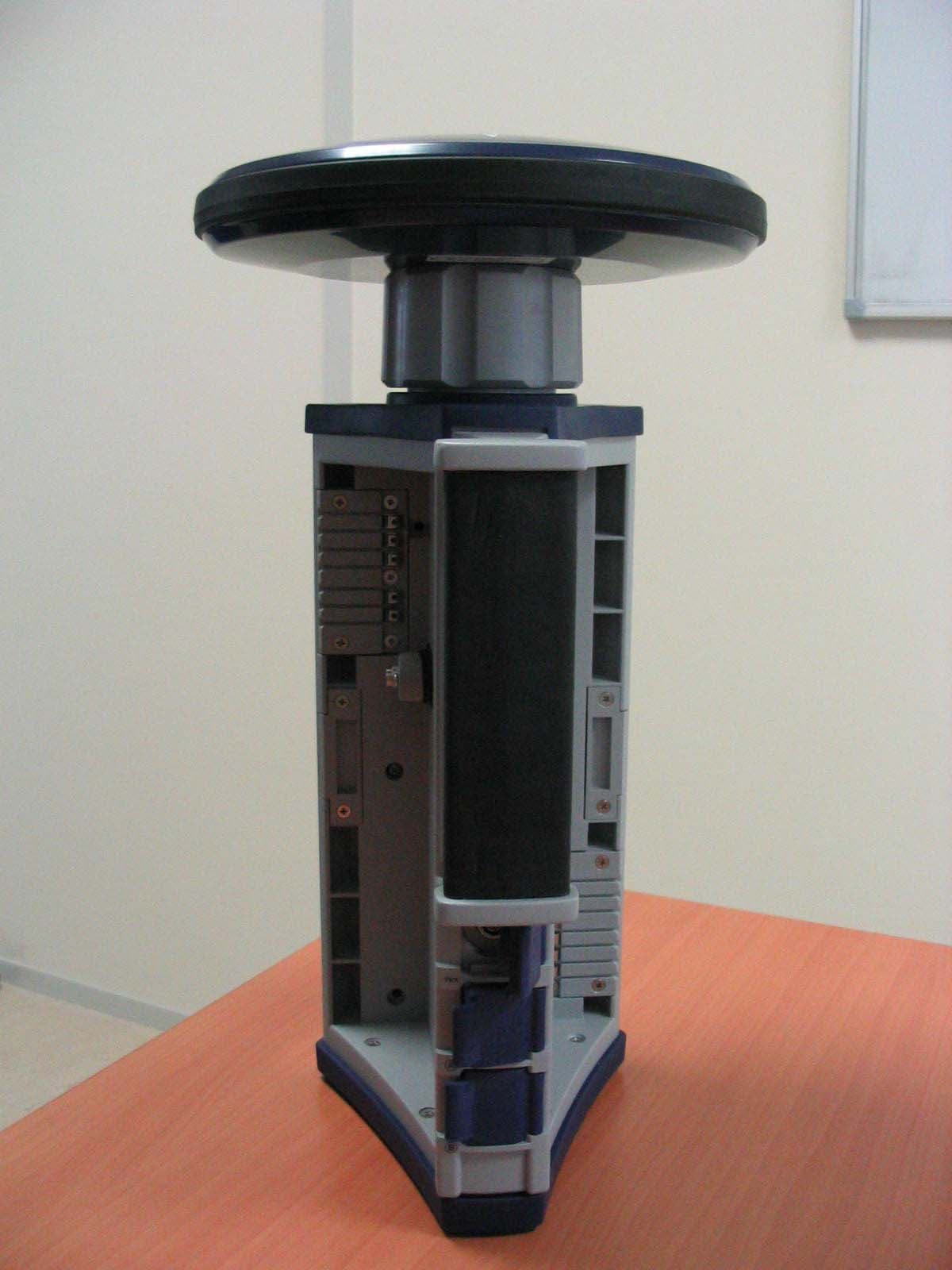
Click to zoom
Application Details
- Equipment Class
- PCT - PCS Licensed Transmitter worn on body
- Date of Grant
- Oct 26, 2003
- Application Purpose
- Original Equipment
- Date of Application
- Oct 26, 2003
- Equipment Note
- Communication Module for GPS Surveying Device
- Frequency Range
- 1850.20000000 - 1909.80000000
- Company
- TRIMBLE EUROPE BV
- Country
- Netherlands
Documents & Files
Document Text
Text extracted from the exhibit documents filed with the FCC. Open a document above to read the original.
Users Manual
RF Safety Exposure To Radio Frequency Energy (SAR) Radio transmitting devices radiate Radio Frequency (RF) energy during its operation. RF energy can be absorbed into the human body and potentially can cause adverse health effects if excessive levels are absorbed. The unit of measurement for human exposure to RF energy is “Specific Absorption Rate” (SAR). The Federal Communications Commission (FCC), Industrie Canada (IC), and other agencies around the world have established limits that incorporate a substantial safety margin designed to assure the safety of all persons using this equipment. In order to certify this unit for sale in the US, Canada and Europe this unit has been tested for RF exposure compliance at a qualified test laboratory and found to comply with the regulations regarding exposure to RF Energy. SAR was measured with the unit transmitting at its maximum certified RF power. Often, however, during normal operation the unit will transmit much less than maximum power. Transmit power is controlled automatically and, in general is reduced as you get closer to a cellular base station. This reduction in transmit power will result in a lower RF energy exposure and resulting SAR value. FCC RF Safety Statement In order to comply with FCC RF exposure safety guidelines as body-worn, normal use of unit, the following must be followed: 1. A distance of AT LEAST 1.5 cm of separation between the users body and the unit. Do NOT use the device in a manner such that it is in direct contact with the body (i.e. on the lap). Such use will likely exceed FCC RF safety exposure limits See www.fcc.gov/oet/rfsafety/ for more information on RF exposure safety. Antenna Care/Unauthorized Modifications Use only the supplied integral antenna. Unauthorized antenna modifications or attachments could damage the unit and may violate FCC regulations. Any changes or modifications not expressly approved by the party responsible for compliance could void the user’s authority to operate the equipment. Maximum Measured SAR Values (W/kg) Band: 1900 MHz Body SAR: 0.016 SAR: ANSI/IEEE C95.1 1992 FCC OET Bulletin 65 Supplement C
Cover Letter(s)
Page 1 of 6 Date: October 1, 2003 RE: Thales Navigation, Inc. FCC ID: NZI110896 In response to your comments on the above referenced Application: General 1) The grantee code NZI on the FCC site does not match the name or address of Thales Navigation located in California. NZI is listed as Dassault Sercel Navigation-Positionnement located in France. Please explain. The grantee code NZI is for Dassault Sercel Navigation-Positionnement, a subsidiary of Thales Navigation and the responsible party for the subject device. 2) The external photographs show various antennas. Due to the number of devices, please label various antennas as RX only, TX/RX, etc for better clarity of the device. Additionally, for any optional accessories, please label these as such. Additionally, it is not clear if the COM module is sold with the unit or is it optional? Note that the users manual appears to show several different options. Due to the number of modules possible, please provide a summary table that helps explain what modules are included, what are optional, what combinations are available, and how each module has been tested for FCC requirements. Please provide further information. The external photographs have been revised. An additional document has been uploaded as an operational description to explain what the various options are. 3) The tune up procedure mentions that there are not any user adjustable components. Note that the tune up procedure is actually regarding the manufacturing process and how the device is set or adjusted to meet FCC regulations. However, in this case the device appears to be a module purchased from Motorola. Therefore an attestation by Thales that explains that they receive the module as adjusted by the manufacturer and do not make any adjustments themselves would be sufficient. Optionally, a tune-up procedure from Motorola could be provided. An attestation by Thales that explains that they receive the module as adjusted by the manufacturer and do not make any adjustments themselves has been uploaded. 4) Please provide additional photographs that show a typical module with the RX installed as well. The internal photographs of the Com Module have been revised to show the placement of the GSM module with respect to both the Thales and the Pacific Crest receivers. Page 2 of 6 5) The FCC ID listed in the operational description (IHDT6ZC1) listed on page 1 is not for a PCS module, but instead a DeskSet phone. Note that the frequency range, emissions designator and other data for this FCC ID do not appear to match the information for this application. Please explain. The operational description has been corrected to reflect the appropriate FCC ID for the GSM module as listed at the top of each page. 6) Please provide a parts list for this application. Note that the schematic of the TX only contains reference designators. The schematics have been updated with the appropriate parts list. As the parts list is to be held confidential, and the confidentiality request asks that the schematics be held confidential, they are to be considered a part of the schematics. EMC 7) FYI.... The theory of operation mentions a conducted output power of +30 dBm, while the test report shows a EIRP power 5.2 dBm. The SAR report offers and explanation for this. Portable device under Part 24 are required to list output power as EIRP. We propose that because of the difference in power, and the fact that Thales Navigation may desire to solve the EIRP problem in the future, to place the conducted power on the grant line with the EIRP power listed in the grant notes. This should allow flexibility to do a Permissive change assuming the conducted power stays the same. Otherwise by placing the EIRP on the grant line would require a new FCC ID every time the EIRP changed. This would be appreciated. Thales is investigating the use of alternative antennas and the use of a Permissive Change rather than a new device approval would make life much easier. 8) The FCC ID on page 2 of 27 of the test report is listed as TBD. Please explain as it was assumed that the same FCC ID would be placed on each model listed. When the report was first drafted the FCC ID was not finalized. The same FCC ID will be placed on each Com Module that contains the GSM module. The “TBD” has been replaced with the correct FCC ID. 9) Page 3 of 27 of the test report appears to contain some missing information regarding the bluetooth and PCS items listed. Please correct. The report has been corrected to include the missing information. Page 3 of 6 10) Is any information available regarding the antenna used in the device (i.e. gain, specs, etc.). The GSM Antenna is a HA-ED2M GSM Antenna from Hankook. The main characteristics of this antenna are: • GSM Bandwidth: 890 - 960MHz • DCS Bandwidth: 1710 - 1880MHz • Impedance: 50 Ohms • Radiation Omni-directional • Polarzation: Vertical • GSM Gain: -1.5 dBi min • DCS Gain: -6dBi min The above characteristics do not take into account the fact that the distance between the Chassis and the GSM Antenna is about 7 to 8 mm. In these conditions of use (i.e. antenna in close proximity to the chassis), the characteristics of the antenna are significantly affected, in particular the Antenna gain. 11) Page 3 & 7 of 17 of the test Report shows an EIRP power of 5.2 dBm (0.003 W), while the test data appears to show 6.5 dBm (0.005 W). Please explain. The data has been corrected to reflect power at 5.2dBm. The wrong information was reported on the data. 12) The bandedge measurements shown on page 7 of 27 does not appear to be performed for the lowest channel of 1850.2 and appear about 1 channel higher. It appears that the channel shown is around 1850.4. Note that the high channel on page 18 of 27 appears ok. Please explain. This was due to software bugs. Although the low channel was not set at 1850.2 MHz, the amplitude of the signals are so low in level the bandedge will still be in compliance. Please state 1850.4 MHz fo…
Text truncated - open the document above for the full version.
Cover Letter(s)
Page 2 of 6 5) The FCC ID listed in the operational description (IHDT6ZC1) listed on page 1 is not for a PCS module, but instead a DeskSet phone. Note that the frequency range, emissions designator and other data for this FCC ID do not appear to match the information for this application. Please explain. The operational description has been corrected to reflect the appropriate FCC ID for the GSM module as listed at the top of each page. 6) Please provide a parts list for this application. Note that the schematic of the TX only contains reference designators. The schematics have been updated with the appropriate parts list. As the parts list is to be held confidential, and the confidentiality request asks that the schematics be held confidential, they are to be considered a part of the schematics. EMC 7) FYI.... The theory of operation mentions a conducted output power of +30 dBm, while the test report shows a EIRP power 5.2 dBm. The SAR report offers and explanation for this. Portable device under Part 24 are required to list output power as EIRP. We propose that because of the difference in power, and the fact that Thales Navigation may desire to solve the EIRP problem in the future, to place the conducted power on the grant line with the EIRP power listed in the grant notes. This should allow flexibility to do a Permissive change assuming the conducted power stays the same. Otherwise by placing the EIRP on the grant line would require a new FCC ID every time the EIRP changed. This would be appreciated. Thales is investigating the use of alternative antennas and the use of a Permissive Change rather than a new device approval would make life much easier. 8) The FCC ID on page 2 of 27 of the test report is listed as TBD. Please explain as it was assumed that the same FCC ID would be placed on each model listed. When the report was first drafted the FCC ID was not finalized. The same FCC ID will be placed on each Com Module that contains the GSM module. The “TBD” has been replaced with the correct FCC ID. 9) Page 3 of 27 of the test report appears to contain some missing information regarding the bluetooth and PCS items listed. Please correct. The report has been corrected to include the missing information. Page 6 of 6 In addition to this document, the following files have been uploaded to the ATCB website to support the above responses: • External Photographs (Revised).pdf • Internal Photographs (Revised).pdf • Addendum to Operational Description.pdf • AC-EX12 Theory of operation (Revised).pdf • R52759-revised.pdf • SAR Report.pdf • SAR Report Appendix A.pdf • SAR Report Appendix B.pdf • SAR Report Appendix C.pdf • AC-EX05 schematics (Revised).pdf • Attestation Letter.pdf • Separation Distances.pdf If you have any additional questions please do not hesitate to contact me via [email protected] . Regards, Mark Briggs Director of Engineering
Cover Letter(s)
American Telecommunications Certification Body Inc. 6731 Whittier Ave, McLean, VA 22101 ` September 26, 2003 RE: Thales Navigation, Inc. FCC ID: NZI110896 (??) After a review of the submitted information, I have a few comments on the above referenced Application. General 1) The grantee code NZI on the FCC site does not match the name or address of Thales Navigation located in California. NZI is listed as Dassault Sercel Navigation-Positionnement located in France. Please explain. 2) The external photographs show various antennas. Due to the number of devices, please label various antennas as RX only, TX/RX, etc for better clarity of the device. Additionally, for any optional accessories, please label these as such. Additionally, it is not clear if the COM module is sold with the unit or is it optional? Note that the users manual appears to show several different options. Due to the number of modules possible, please provide a summary table that helps explain what modules are included, what are optional, what combinations are available, and how each module has been tested for FCC requirements. Please provide further information. 3) The tune up procedure mentions that there are not any user adjustable components. Note that the tune up procedure is actually regarding the manufacturing process and how the device is set or adjusted to meet FCC regulations. However, in this case the device appears to be a module purchased from Motorola. Therefore an attestation by Thales that explains that they receive the module as adjusted by the manufacturer and do not make any adjustments themselves would be sufficient. Optionally, a tune-up procedure from Motorola could be provided. 4) Please provide additional photographs that show a typical module with the RX installed as well. 5) The FCC ID listed in the operational description (IHDT6ZC1) listed on page 1 is not for a PCS module, but instead a DeskSet phone. Note that the frequency range, emissions designator and other data for this FCC ID do not appear to match the information for this application. Please explain. 6) Please provide a parts list for this application. Note that the schematic of the TX only contains reference designators. EMC 7) FYI....The theory of operation mentions a conducted output power of +30 dBm, while the test report shows a EIRP power 5.2 dBm. The SAR report offers and explanation for this. Portable device under Part 24 are required to list output power as EIRP. We propose that because of the difference in power, and the fact that Thales Navigation may desire to solve the EIRP problem in the future, to place the conducted power on the grant line with the EIRP power listed in the grant notes. This should allow flexibility to do a Permissive change assuming the conducted power stays the same. Otherwise by placing the EIRP on the grant line would require a new FCC ID every time the EIRP changed. 8) The FCC ID on page 2 of 27 of the test report is listed as TBD. Please explain as it was assumed that the same FCC ID would be placed on each model listed. 9) Page 3 of 27 of the test report appears to contain some missing information regarding the bluetooth and PCS items listed. Please correct. 10) Is any information available regarding the antenna used in the device (i.e. gain, specs, etc.). 11) Page 3 & 7 of 17 of the test Report shows an EIRP power of 5.2 dBm (0.003 W), while the test data appears to show 6.5 dBm (0.005 W). Please explain. 12) The bandedge measurements shown on page 7 of 27 does not appear to be performed for the lowest channel of 1850.2 and appear about 1 channel higher. It appears that the channel shown is around 1850.4. Note that the high channel on page 18 of 27 appears ok. Please explain. --- Continued on Next Page --- z Page 2September 26, 2003 13) Note that as of last week, the FCC has retracted their requirement of performing all block edge tests, however please note that bandedge tests are still required (see attachment). It is no longer required to submit this data. 14) The conducted power listed on page 7 of 17 was listed as 28 dBm. Is this listed elsewhere in the measurement report? This is typically used for comparison of data take by the SAR facility. Note that this level must agree with SAR report and tune-up procedure however the conducted power in SAR report should be greater than or equal to what’s in EMC report, but not exceeding tune-up/tolerance. Note the value appears higher than given in the SAR report. 15) The frequency stability results shown on page 7 of 17 do not appear to match the data in the measurement report. 16) The test report mentions that the receivers have been tested to meet FCC requirements. However the device only meets the Class A digital device limits. Note that the RX portion of the device must meet with Class B limits, even if the total device only meets with Class A limits. Please explain. SAR 17) Please adjust the statement of compliance on page 4 to include FCC 47 CFR §2.1093 and that the device was tested in accordance with the measurement standards and procedures specified in FCC OET Bulletin 65, Supplement C (Edition 01-01). 18) The Distance between the measurement point (distance + offset) at the probe sensor location (geometric center behind the probe tip) and the phantom surface should be < 8.0 mm and maintained at a constant distance of +/- 1.0 mm during an area scan to determine peak SAR locations as specified on page 15 of the report. However, section 6.4 (page 20) states that it was performed at 8.0 mm. Please explain. 19) The SAR report should define if the unit under test is a production unit or identical prototype (47 CFR §2.908). 20) The SAR report included Appendix's 1, 2, 5. Are appendix's 3 & 4 missing? 21) The thermometer and dipole given in the test equipment appear to possibly be out of calibration. Please explain. 22) The field probe calibration information/certificate does not appear to address the measurements uncertainty associated with these mea…
Text truncated - open the document above for the full version.
External Photos
EXTERNAL PHOTOGRAPHS Front View of The System – GPS antenna but no UHF antenna Rear View of The System – GPS antenna but no UHF antenna Battery Module Com Module GSM antenna integral to Com Module (Transmit/ Receive) GPS Receiver Antenna (Receive only) Side View of The System – GPS antenna and UHF antenna UHF antenna (receive Only) GPS antenna (Receive Only) GSM Antenna (transmit / receive) Rear View – Battery module and Com Module Removed Com Module front and rear views Connection to UHF Receiver’s antenna GSM antenna
ID Label/Location Info
Label and Label Location The label (see following page) is located on the outside of the Com Module as shown below. The label is bonded to the module using a permanent acrylic adhesive and has a clear plastic overlay to provide a permanent, durable finish. Label location Com Module Labels.doc DÉSIGNATION/TITLE Etiquettes Z-MAX PLAN N° / DRAWING No. FOLIO SHEET __________ 1/1 C.D F.t N° M PD A 101921 C CE DOCUMENT EST LA PROPRIÉTÉ INALIÉABLE DE THALES NAVIGATION/REPRODUCTION & DIFFUSION INTERDITES THIS DRAWING IS THE EXCLUSIVE PROPERTY OF THALES NAVIGATION/REPRODUCTION AND UNAUTHORIZED USE ARE FORBIDDEN ÉTABLI PAR/DRAWN BY Ph TESSIER DATE DE CREATION 03 Août 2003 VÉRIFIÉ PAR/CHECKED BY: Ch. LEGRAS INDICE INDEX ECO ou/or M DATE B 03187 C 03198 Etiquette 101921 Dim : 78 x 38 Codification du numéro de série Numéro de série S/N : YYYYWWNNN YYYY : année (2003) WW : Semaine de fabrication Product Label – Com Module with GSM and UHF Receivers Installed Product Label – Com Module without UHF Receiver Installed (GSM module only) Product Label – Com Module without GSM Module Installed (UHF Receiver only) TYPE : COM MOD,GSM+PDL410-430 P/N : 800964-08 S/N : 200326001 MADE IN FRANCE FCC ID : NZI110896 IC ID : 4713A-110896 IC ID : 4713A-800964 This device complies with part 15 of the FCC rules. Operation is subject to the following conditions: (1) This device may not cause harmful interference, and (2) this device must accept any interference received, including interference that may cause undesired operation Tested to Comply With FCC Standards TYPE : COM MOD,GSM P/N : 800964-08 S/N : 200326001 MADE IN FRANCE FCC ID : NZI110896 IC ID : 4713A-110896 This device complies with part 15 of the FCC rules. Operation is subject to the following conditions: (1) This device may not cause harmful interference, and (2) this device must accept any interference received, including interference that may cause undesired operation TYPE : COM MOD, PDL410-430 P/N : 800964-08 S/N : 200326001 MADE IN FRANCE IC ID : 4713A-800964 This device complies with part 15 of the FCC rules. Operation is subject to the following conditions: (1) This device may not cause harmful interference, and (2) this device must accept any interference received, including interference that may cause undesired operation Tested to Comply With FCC Standards
Internal Photos
INTERNAL PHOTOGRAPHS – GSM TRx Internal view of Com Module showing location of GSM module mounted to control circuit board (note, no receiver module installed in top photograph). GSM module and Thales Receiver installed in the Com Module GSM module and Pacific Crest Receiver installed in the Com Module APPLICANT: THALES FCC ID: NZI110896 Internal Photographs Typical Non-Housed Unit (Bottom View) Typical Non-Housed Unit (Top View Showing ID Label on Shields) APPLICANT: THALES FCC ID: NZI110896 Internal Photographs Typical Unit (Bottom View Shields Removed) Typical Unit (Top View Shields Removed) Note: External connector type varies depending upon model
Parts List/Tune Up Info
APPLICANT: MOTOROLA, INC.FCC ID: IHDT6AC1 EXHIBIT 10 TRANSCEIVER ADJUSTMENTS/TUNE-UP PROCEDURE There are no user accessible adjustments or tuning in this portable cellular transceiver. All necessary adjustments and tuning are performed during manufacture of the product. Any adjustments or tuning after service or repair are done as part of that process as special equipment is required to perform such adjustments.
RF Exposure Info
Accredited according to ISO/IEC 17025 by: TTI-P-G 81/94-A0 CETECOM Inc. 411 Dixon Landing Road Milpitas, CA 95035 U.S.A. Phone: + 1 (408) 586 6200 Fax: + 1 (408) 586 6299 E-mail: [email protected] http://www.cetecom.com CETECOM Inc. is a Delaware Corporation with Corporation number: 2113686 Board of Directors: Dr. Harald Ansorge, Dr. Klaus Matkey, Hans Peter May V.2.16M-2002-03-12 \\stupendousman\rootappsdata\emc\projects_emc\thales\547_2003\report\sar_547_2003_fcc_1900_ver2.doc © Copyright by CETECOM SAR Test Report No. SAR_547_2003_FCC_1900_ver2 for the Thales Navigation Z-Max GPS Receiver Mobile surveying instrument Model Number: 800963 for Z- Max Receiver 110896 for the GSM Module FCC ID: NZI800963 for Z- Max Receiver NZI110896 for the GSM Module Date of Report: 09/30/2003 Date of issue: 09/30/2003 Report Copy No.: 01 SAR Test Report No. SAR_547_2003_FCC_1900_ver2 Date of Report: 09/30/2003 Page 2 of 29 This report shall not be reproduced except in full without the written approval of: CETECOM Inc. SAR 411 Dixon Landing Road Milpitas, CA 95035 U.S.A. Contents 1. ASSESSMENT ...................................................................................................................4 2. ADMINISTRATIVE DATA...................................................................................................5 2.1. Identification of the Testing Laboratory Issuing the SAR Assessment Report ...............5 2.2. Identification of the Client...........................................................................................5 2.3. Identification of the Manufacturer...............................................................................5 3. EQUIPMENT UNDER INVESTIGATION (EUI)...................................................................6 3.1. Identification of the Equipment under Investigation ...................................................6 3.2. Front View of the Equipment under Investigation ......................................................7 4. SUBJECT OF INVESTIGATION ........................................................................................8 4.1. The IEEE Standard C95.1 and the FCC Exposure Criteria .......................................8 4.2. Distinction Between Exposed Population, Duration of Exposure and Frequencies...8 4.3. Distinction between Maximum Permissible Exposure and SAR Limits......................9 4.4. SAR Limit ...................................................................................................................9 5. THE FCC MEASUREMENT PROCEDURE .....................................................................10 5.1. General Requirements.............................................................................................10 5.2. Device Operating Next to a Person’s Ear ................................................................10 5.3. Test positions of device relative to head..................................................................11 5.4. Test to be Performed ...............................................................................................14 5.5. Body-worn and Other Configurations.......................................................................14 5.6. Procedure for assessing the peak spatial-average SAR .........................................15 5.7. Determination of the largest peak spatial-average SAR ..........................................17 6. THE MEASUREMENT SYSTEM ......................................................................................18 6.1. Robot system specification ......................................................................................18 6.2. Probe and amplifier specification .............................................................................19 6.3. Phantoms.................................................................................................................19 6.4. SAR measurement procedure .................................................................................20 6.5. SARA2 Interpolation and Extrapolation schemes ....................................................20 SAR Test Report No. SAR_547_2003_FCC_1900_ver2 Date of Report: 09/30/2003 Page 3 of 29 This report shall not be reproduced except in full without the written approval of: CETECOM Inc. SAR 411 Dixon Landing Road Milpitas, CA 95035 U.S.A. 6.6. Interpolation of 2D area scan...................................................................................21 6.7. Extrapolation of 3D scan..........................................................................................21 6.8. Interpolation of 3D scan and volume averaging.......................................................21 7. UNCERTAINTY ASSESSMENT.......................................................................................23 7.1. Table of Measurement Uncertainty Values of SAR Evaluations..............................24 7.2. Table of Measurement Uncertainty Values for SAR System Verification ................25 8. TEST RESULTS SUMMARY............................................................................................26 8.1. Description of EUT test positions and operation modes ..........................................26 8.2. Conducted Output Power.........................................................................................26 8.3. Radiated Output Power............................................................................................26 8.4. Body SAR results for GSM 1900MHz band for Z-Max GPS Receiver .....................27 8.5. Validation Check Results .........................................................................................28 9. REFERENCES..................................................................................................................29 SAR Test Report No. SAR_547_2003_FCC_1900_ver2 Date of Report: 09/30/2003 Page 4 of 29 This report shall not be reproduced except in full without …
Text truncated - open the document above for the full version.
RF Exposure Info
SAR Test Report No.: SAR_547_2003_FCC_1900_ver2 Date of Report: 9/30/2003 Appendix A Plots Page 1 of 4 Date / Time: 9/8/2003 11:38:59 AM Position: side 1.5cm Filename: *.txt Phantom: HeadBox_new_spout.csv Device Tested: Thales Z-Max Head Rotation: 0 Antenna: integral Test Frequency: 1880 Shape File: thales_gsm_ant.csv Power Level: maximum Probe: 0106 Cal File: 106_1900_BODY_GSM X Y Z Air 415 805 371 DCP 9.4 2.7 7.8 Cal Factors: Lin 0.47 7 0.47 7 0.47 7 Amp Gain: 2 Averaging: 6 Batteries Replaced: 09/03/2003 Liquid: 1900 Type: Body Conductivity: 1.547 Relative Permittivity: 53.27 Liquid Temp (deg C): 22.0 Ambient Temp (deg C): 22.0 Ambient RH (%): 50 Density (kg/m3): 1000 Software Version: 0.420 ZOOM SCAN RESULTS: Start Scan End Scan Spot SAR (W/kg): 0.007 0.007 Change during Scan (%) -0.00 Max E-field (V/m): 3.83 1g 10g Max SAR (W/kg) 0.016 0.009 X Y Z Location of Max (mm): 75.0 28.0 -187.7 AREA SCAN: Min Max Steps Y 80.0 -20.0 10.0 Scan Extent: Z -200.0 -110.0 10.0 SAR Test Report No.: SAR_547_2003_FCC_1900_ver2 Date of Report: 9/30/2003 Appendix A Plots Page 2 of 4 Date / Time: 9/8/2003 12:09:04 PM Position: side 1.5cm Filename: *.txt Phantom: HeadBox_new_spout.csv Device Tested: Thales Z-Max Head Rotation: 0 Antenna: integral Test Frequency: 1850.2 Shape File: thales_gsm_ant.csv Power Level: maximum Probe: 0106 Cal File: 106_1900_BODY_GSM X Y Z Air 415 805 371 DCP 9.4 2.7 7.8 Cal Factors: Lin 0.47 7 0.47 7 0.47 7 Amp Gain: 2 Averaging: 6 Batteries Replaced: 09/03/2003 Liquid: 1900 Type: Body Conductivity: 1.536 Relative Permittivity: 53.42 Liquid Temp (deg C): 22.0 Ambient Temp (deg C): 22.0 Ambient RH (%): 50 Density (kg/m3): 1000 Software Version: 0.420 ZOOM SCAN RESULTS: Start Scan End Scan Spot SAR (W/kg): 0.002 0.002 Change during Scan (%) 0.00 Max E-field (V/m): 2.54 1g 10g Max SAR (W/kg) 0.007 0.004 X Y Z Location of Max (mm): 75.1 25.0 -189.9 AREA SCAN: Min Max Steps Y 80.0 -20.0 10.0 Scan Extent: Z -200.0 -110.0 10.0 SAR Test Report No.: SAR_547_2003_FCC_1900_ver2 Date of Report: 9/30/2003 Appendix A Plots Page 3 of 4 Date / Time: 9/8/2003 12:35:50 PM Position: side 1.5cm Filename: *.txt Phantom: HeadBox_new_spout.csv Device Tested: Thales Z-Max Head Rotation: 0 Antenna: integral Test Frequency: 1909.8 Shape File: thales_gsm_ant.csv Power Level: maximum Probe: 0106 Cal File: 106_1900_BODY_GSM X Y Z Air 415 805 371 DCP 9.4 2.7 7.8 Cal Factors: Lin 0.47 7 0.47 7 0.47 7 Amp Gain: 2 Averaging: 6 Batteries Replaced: 09/03/2003 Liquid: 1900 Type: Body Conductivity: 1.569 Relative Permittivity: 53.21 Liquid Temp (deg C): 22.0 Ambient Temp (deg C): 22.0 Ambient RH (%): 50 Density (kg/m3): 1000 Software Version: 0.420 ZOOM SCAN RESULTS: Start Scan End Scan Spot SAR (W/kg): 0.004 0.004 Change during Scan (%) -0.74 Max E-field (V/m): 3.43 1g 10g Max SAR (W/kg) 0.014 0.008 X Y Z Location of Max (mm): 75.0 26.0 -187.9 AREA SCAN: Min Max Steps Y 80.0 -20.0 10.0 Scan Extent: Z -200.0 -110.0 10.0 SAR Test Report No.: SAR_547_2003_FCC_1900_ver2 Date of Report: 9/30/2003 Appendix A Plots Pa…
Text truncated - open the document above for the full version.
Contact Information
Applicant
Helena Fredenberg(Product Compliance Engineer)
Technical Contact
Elliott Laboratories Inc.Juan Martinez
[email protected]408-245-7800
684 West Maude Ave. · Sunnyvale, California · United States
Non-Technical Contact
Elliott Laboratories Inc.Juan Martinez
[email protected]408-245-7800
Test Firm
Elliott Laboratories LLCDavid Bare
Technical Specifications
| # | Rule Parts | Frequency Range | Power Output | Emission | Tolerance |
|---|---|---|---|---|---|
| 1 | 24E | 1.85 GHz - 1.91 GHz | 589.00 mW | 317KGXW | 0.1000000000 ppm |
Other Applications from TRIMBLE EUROPE BV
NZI-11705920
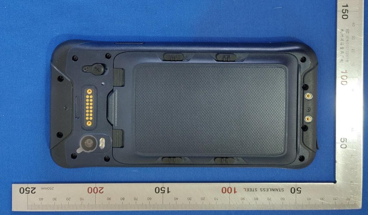
May 09, 2021Rugged Smart Phone
Equipment Class
NII - Unlicensed National Information Infrastructure TX
NZI802168
Mar 17, 2014MobileMapper 20, WCDMA/GSM/GPS Portable Receiver
Equipment Class
DSS - Part 15 Spread Spectrum Transmitter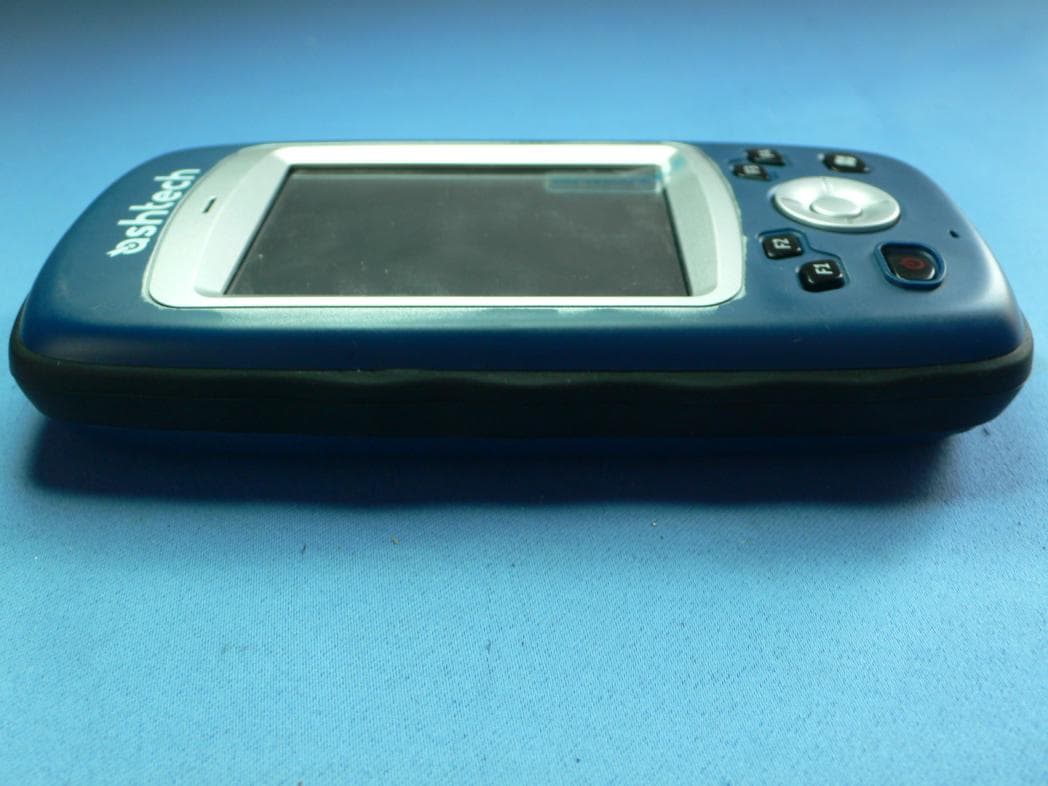
NZI802140
May 24, 2011Portable GNSS Receiver
Equipment Class
DTS - Digital Transmission System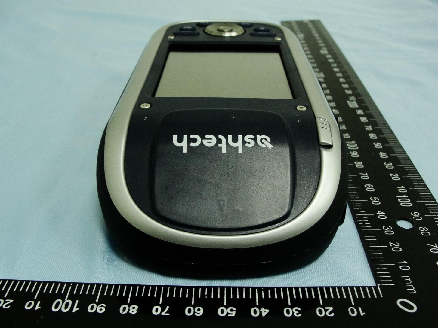
NZI802111A
Nov 18, 2010MobileMapper 100, ProMark 100 and ProMark 200
Equipment Class
DSS - Part 15 Spread Spectrum Transmitter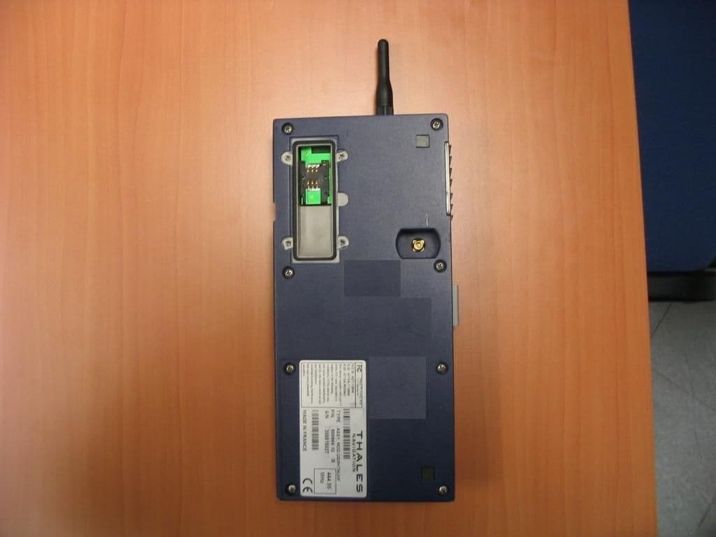
NZI111256
Oct 04, 2006Zmax Communication Unit
Equipment Class
PCT - PCS Licensed Transmitter worn on body