NZI800963GPS Surveying Device with Built In Bluetooth
TRIMBLE EUROPE BVApplication Details
- Equipment Class
- DSS - Part 15 Spread Spectrum Transmitter
- Date of Grant
- Sep 24, 2003
- Application Purpose
- Original Equipment
- Date of Application
- Sep 24, 2003
- Equipment Note
- GPS Surveying Device with Built In Bluetooth
- Frequency Range
- 2402.00000000 - 2480.00000000
- Company
- TRIMBLE EUROPE BV
- Country
- Netherlands
Documents & Files
Document Text
Text extracted from the exhibit documents filed with the FCC. Open a document above to read the original.
Cover Letter(s)
Page 1 of 3 September 26, 2003 RE: Thales Navigation, Inc. FCC ID: NZI800963 In response to your comments on the above referenced Application: 1) The grantee code NZI on the FCC site does not match the name or address of Thales Navigation located in California. NZI is listed as Dassault Sercel Navigation-Positionnement located in France. Please explain. The grantee code NZI is for Dassault Sercel Navigation-Positionnement, a subsidiary of Thales Navigation and the responsible party for the subject device. 2) The FCC labeling should include a colon after the term FCC ID. Please adjust the labeling to include this. A revised label and label location drawing have been uploaded to the ATCB website. 3) The system block diagram shows a GSM transceiver which does not appear to be part of this application. Please explain. The GSM transceiver is incorporated as an optional extra to a Com Module. A separate application for the Com module with the GSM transceiver has been filed with ATCB. The application will show that the Com Module is to be used with the host device described in this application. 4) The external photographs show various antennas. Due to the number of devices, please label various antennas as RX only, TX/RX, etc for better clarity of the device. Additionally, for any optional accessories, please label these as such. Additionally, the photographs appear to show the COM module which does not appear to be included as part of this application. Is this sold with the unit or is it optional? Note that the users manual appears to show several different options. Due to the number of modules possible, please provide a summary table that helps explain what modules are included, what are optional, what combinations are available, and how each module has been tested for FCC requirements. Please provide further information. The external photographs have been revised. An additional document has been uploaded as an operational description to explain what the various options are. Page 2 of 3 5) From the internal photographs of the device, it is uncertain if the device contains additional boards/circuits in addition to the single board shown. Please provide additional internal photographs to sufficiently show the general construction of the rest of the device. Internal photographs have been revised to show the construction of the main unit in relation to the circuit board containing the BlueTooth transceiver. 6) It is uncertain what the base radio/antennas are given on page 5 of the users manual. Are these different devices or related to the unit being certified. Please explain. The antenna on page 5 of the user’s manual are for UHF transceivers that a surveyor may use. These devices would be data modems connected to the serial port of this device. 7) Page 4 of 19 of the test report appear to mention every configuration except for the bluetooth covered by this application. Correct, the note in the test report is to indicate the additional tests and certifications being sought for this device. 8) Please explain the use of a 1 GHz high pass filter given in the test report. The fundamental of this device should operate in the 2400 MHz band. The 1GHz high pass filter is used to reduce instrumentation sensitivity to local ambient signals in the 800 MHz band. The relatively low output power from the BlueTooth device allowed measurements to be made of the spurious emissions from the transmitter without the use of a high-pass filter. 9) Page 3 of 20 of the test report appears to contain some missing information regarding the bluetooth and PCS items listed. Please correct. The report has been corrected to include the missing information. 10) The power output listed on page 13 of 20 does not match the test results. Please correct. The report has been corrected. Page 3 of 3 11) The test report mentions that the receivers have been tested to meet FCC requirements. However the device only meets the Class A digital device limits. Note that the RX portion of the device must meet with Class B limits, even if the total device only meets with Class A limits. Please explain. The receivers have been evaluated against the appropriate limits of FCC Part 15.109. The digital device has also been evaluated against both Class A limits (with USB and AC-DC adapter connected) and Class B limits (USB and external power disconnected). In addition to this document, the following files have been uploaded to the ATCB website to support the above responses: • External Photographs (Revised).pdf • Revised Label and label location (Main unit).pdf • Internal Photographs (Revised).pdf • R52549 Revision 1.pdf • Addendum to Operational Description.pdf If you have any additional questions please do not hesitate to contact me via [email protected] . Regards, Mark Briggs Director of Engineering
Contact Information
Applicant
Helena Fredenberg(Product Compliance Engineer)
Technical Contact
Elliott Laboratories Inc.Mark Briggs
[email protected]408-245-7800
684 West Maude Ave. · Sunnyvale, California · United States
Non-Technical Contact
Elliott Laboratories Inc.David Guidotti
[email protected]408-245-7800
Test Firm
Elliott Laboratories LLCDavid Bare
Technical Specifications
| # | Rule Parts | Frequency Range | Power Output |
|---|---|---|---|
| 1 | 15C | 2.40 GHz - 2.48 GHz | 2.50 mW |
Other Applications from TRIMBLE EUROPE BV
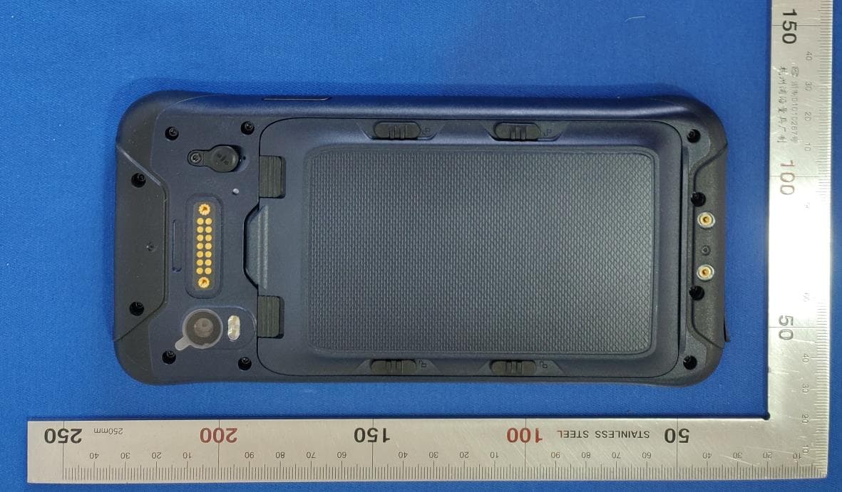
NZI-11705920
May 09, 2021Rugged Smart Phone
Equipment Class
NII - Unlicensed National Information Infrastructure TX
NZI802168
Mar 17, 2014MobileMapper 20, WCDMA/GSM/GPS Portable Receiver
Equipment Class
DSS - Part 15 Spread Spectrum Transmitter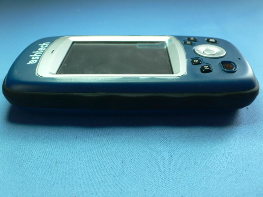
NZI802140
May 24, 2011Portable GNSS Receiver
Equipment Class
DTS - Digital Transmission System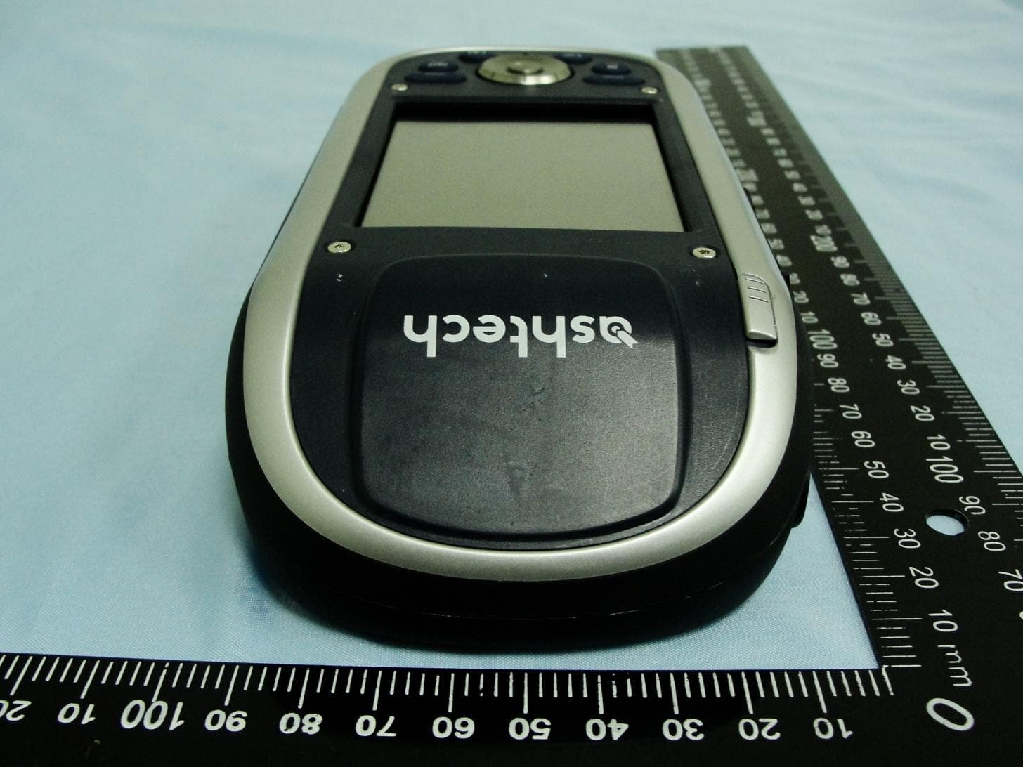
NZI802111A
Nov 18, 2010MobileMapper 100, ProMark 100 and ProMark 200
Equipment Class
DSS - Part 15 Spread Spectrum Transmitter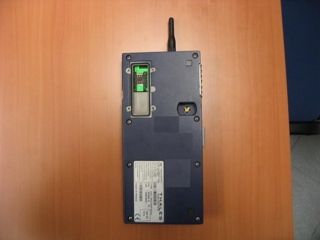
NZI111256
Oct 04, 2006Zmax Communication Unit
Equipment Class
PCT - PCS Licensed Transmitter worn on body