O2E-ILR-916IP3UHF Intelligent Long Range Interrogator System
Identec Solutions, Inc.
Click to zoom
Application Details
- Equipment Class
- DXT - Part 15 Low Power Transceiver, Rx Verified
- Date of Grant
- Mar 25, 2003
- Application Purpose
- Original Equipment
- Date of Application
- Mar 25, 2003
- Equipment Note
- UHF Intelligent Long Range Interrogator System
- Frequency Range
- 916.50000000 - 916.50000000
- Company
- Identec Solutions, Inc.
- Country
- Canada
Documents & Files
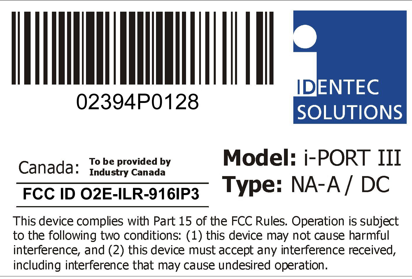
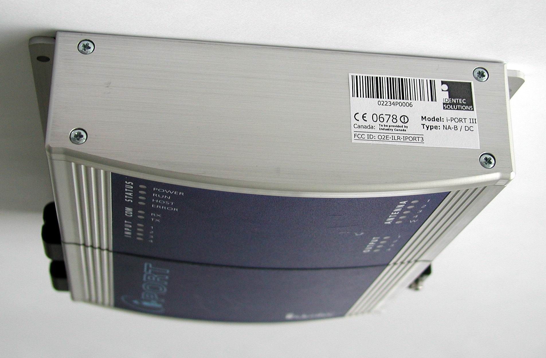
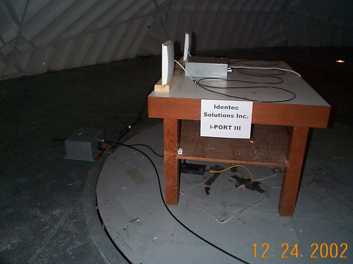
Document Text
Text extracted from the exhibit documents filed with the FCC. Open a document above to read the original.
Users Manual
_______________________________________________________________________ i-PORT III Installation Manual IDENTEC SOLUTIONS, Inc. Suite 102, 1860 Dayton Street Kelowna, British Columbia Canada V1Y 7W6 Tel: (250) 860-6567 Fax: (250) 860-6541 www.identecsolutions.com _________________________________________________________________________ Document #7201-002, Rev C Page 2 Disclaimer and Limitation of Liability IDENTEC SOLUTIONS, Inc. and its affiliates, subsidiaries, officers, directors, employees and agents provide the information contained in this Manual on an “as-is” basis and do not make any express or implied warranties or representations with respect to such information including, without limitation, warranties as to non- infringement, reliability, fitness for a particular purpose, usefulness, completeness, accuracy or currentness. IDENTEC SOLUTIONS, Inc. shall not in any circumstances be liable to any person for any special, incidental, indirect or consequential damages, including without limitation, damages resulting from use of or reliance on information presented herein, or loss of profits or revenues or costs of replacement goods, even if informed in advance of the possibility of such damages. Trademarks “IDENTEC SOLUTIONS”, “Intelligent Long Range”, “ILR” and the stylized “i” are registered trademarks and “i-Q”, “i-D”, “i-CARD”, “i-PORT”, “i-LINKS”, “Solutions. It’s in our name.” are trademarks of IDENTEC SOLUTIONS, Inc. and/or IDENTEC SOLUTIONS AG. Copyright Notice Copyright © 2002 IDENTEC SOLUTIONS, Inc. All rights reserved. No part of this document may be reproduced or transmitted in any form by any means, photographic, electronic, mechanical or otherwise, or used in any information storage and retrieval system, without the prior written permission of IDENTEC SOLUTIONS, Inc. _________________________________________________________________________ Document #7201-002, Rev C Page 3 Radio Frequency Compliance Statement IDENTEC SOLUTIONS, Inc. is the responsible party for the compliance of the following devices: MODEL: i-PORT III i-CARD i-D2 TAGS i-Qxx TAGS FCC ID: O2E-ILR-916IP3 O2E-ICARD-NA OO4-ILR-ID2 OO4-ILR-IQ8T or OO4-ILR-IQR CANADA: Pending 35381032231 3538A12112 35381021756A or 35381021825 The user(s) of these products are cautioned to only use accessories and peripherals approved, in advance, by IDENTEC SOLUTIONS, Inc. The use of accessories and peripherals, other than those approved by IDENTEC SOLUTIONS, Inc., or unauthorized changes to approved products, may void the compliance of these products and may result in the loss of the user(s) authority to operate the equipment. Operation is subject to the following conditions: (1) these devices may not cause harmful interference, and (2) these devices must accept any interference, including interference that may cause undesired operation of the device. FCC Compliance This equipment has been tested and found to comply with the limits for a Class A digital device, pursuant to Part 15 of the FCC Rules. These limits are designed to provide reasonable protection against harmful interference when the equipment is operated in a commercial environment. This equipment generates, uses, and can radiate radio frequency energy and, if not installed and used in accordance with the instruction manual, may cause harmful interference to radio communication. Operation of this equipment in a residential area is likely to cause harmful interference in which case the user will be required to correct the interference at his/her own expense. Warning: Changes or modifications to this unit not expressly approved by the party responsible for compliance could void the user’s authority to operate the equipment. Industry Canada Compliance This Class A digital apparatus meets all requirements of the Canadian Interference-Causing Equipment Regulations. Cet appareil numérique de la classe A respecte toutes les exigences du Règlement sur le matériel brouilleur du Canada. To reduce potential radio interference to other users, the antenna type and its gain should be so chosen that the equivalent isotropically radiated power (EIRP) is not more than that required for successful communication. This device has been designed to operate with an antenna having a maximum gain of 8dBi. Antenna having a higher gain is strictly prohibited per regulations of Industry Canada. The required antenna impedance is 50 ohms. Important Note To comply with FCC radio frequency exposure compliance requirements, this device must be installed by an IDENTEC SOLUTIONS certified technician. When installing antennas, a 20 centimeter passing distance must be maintained from any body part of the user or nearby persons and the antenna. The installer of this radio equipment must ensure that the antenna is located or pointed such that it does not emit RF field in excess of Health Canada limits for the general population; consult Safety Code 6, obtainable from Health Canada. _________________________________________________________________________ Document #7201-002, Rev C Page 4 Table of Contents 1.0 INTRODUCTION........................................................................................................................................5 1.1 FUNDAMENTALS.........................................................................................................................................5 1.2 SYSTEM OVERVIEW....................................................................................................................................5 2.0 INSTALLATION AND START-UP...........................................................................................................6 2.1 INSTALLATION AND START-UP...................................................................................................................6 CABLE CONNECTIONS AND PLUG ALLOCATION....................................................................................................12 3.0 SOFTWARE, CONFIGURATION...…
Text truncated - open the document above for the full version.
Users Manual
_______________________________________________________________________ i-PORT III User’s Guide IDENTEC SOLUTIONS, Inc. Suite 102, 1860 Dayton Street Kelowna, British Columbia Canada V1Y 7W6 Tel: (250) 860-6567 Fax: (250) 860-6541 www.identecsolutions.com _________________________________________________________________________ Document #7201-003, Rev B Page 2 Disclaimer and Limitation of Liability IDENTEC SOLUTIONS, Inc. and its affiliates, subsidiaries, officers, directors, employees and agents provide the information contained in this Manual on an “as-is” basis and do not make any express or implied warranties or representations with respect to such information including, without limitation, warranties as to non- infringement, reliability, fitness for a particular purpose, usefulness, completeness, accuracy or currentness. IDENTEC SOLUTIONS, Inc. shall not in any circumstances be liable to any person for any special, incidental, indirect or consequential damages, including without limitation, damages resulting from use of or reliance on information presented herein, or loss of profits or revenues or costs of replacement goods, even if informed in advance of the possibility of such damages. Trademarks “IDENTEC SOLUTIONS”, “Intelligent Long Range”, “ILR” and the stylized “i” are registered trademarks and “i-Q”, “i-D”, “i-CARD”, “i-PORT”, “i-LINKS”, “Solutions. It’s in our name.” are trademarks of IDENTEC SOLUTIONS, Inc. and/or IDENTEC SOLUTIONS AG. Copyright Notice Copyright © 2002 IDENTEC SOLUTIONS, Inc. All rights reserved. No part of this document may be reproduced or transmitted in any form by any means, photographic, electronic, mechanical or otherwise, or used in any information storage and retrieval system, without the prior written permission of IDENTEC SOLUTIONS, Inc. _________________________________________________________________________ Document #7201-003, Rev B Page 3 Radio Frequency Compliance Statement IDENTEC SOLUTIONS, Inc. is the responsible party for the compliance of the following devices: MODEL: i-PORT III i-CARD i-D2 TAGS i-Qxx TAGS FCC ID: O2E-ILR-916IP3 O2E-ICARD-NA OO4-ILR-ID2 OO4-ILR-IQ8T or OO4-ILR-IQR CANADA: Pending 35381032231 3538A12112 35381021756A or 35381021825 The user(s) of these products are cautioned to only use accessories and peripherals approved, in advance, by IDENTEC SOLUTIONS, Inc. The use of accessories and peripherals, other than those approved by IDENTEC SOLUTIONS, Inc., or unauthorized changes to approved products, may void the compliance of these products and may result in the loss of the user(s) authority to operate the equipment. Operation is subject to the following conditions: (1) these devices may not cause harmful interference, and (2) these devices must accept any interference, including interference that may cause undesired operation of the device. FCC Compliance This equipment has been tested and found to comply with the limits for a Class A digital device, pursuant to Part 15 of the FCC Rules. These limits are designed to provide reasonable protection against harmful interference when the equipment is operated in a commercial environment. This equipment generates, uses, and can radiate radio frequency energy and, if not installed and used in accordance with the instruction manual, may cause harmful interference to radio communication. Operation of this equipment in a residential area is likely to cause harmful interference in which case the user will be required to correct the interference at his/her own expense. Warning: Changes or modifications to this unit not expressly approved by the party responsible for compliance could void the user’s authority to operate the equipment. Industry Canada Compliance This Class A digital apparatus meets all requirements of the Canadian Interference-Causing Equipment Regulations. Cet appareil numérique de la classe A respecte toutes les exigences du Règlement sur le matériel brouilleur du Canada. To reduce potential radio interference to other users, the antenna type and its gain should be so chosen that the equivalent isotropically radiated power (EIRP) is not more than that required for successful communication. This device has been designed to operate with an antenna having a maximum gain of 8dBi. Antenna having a higher gain is strictly prohibited per regulations of Industry Canada. The required antenna impedance is 50 ohms. Important Note To comply with FCC radio frequency exposure compliance requirements, this device must be installed by an IDENTEC SOLUTIONS certified technician. When installing antennas, a 20 centimeter passing distance must be maintained from any body part of the user or nearby persons and the antenna. The installer of this radio equipment must ensure that the antenna is located or pointed such that it does not emit RF field in excess of Health Canada limits for the general population; consult Safety Code 6, obtainable from Health Canada. _________________________________________________________________________ Document #7201-003, Rev B Page 4 Table of Contents 1.0 INTRODUCTION........................................................................................................................................5 1.1 FUNDAMENTALS.........................................................................................................................................5 1.2 SYSTEM OVERVIEW....................................................................................................................................5 2.0 COMPONENTS...........................................................................................................................................6 2.1 I-PORT III..................................................................................................................................................6 2.2 ANTENNAS....................................................................................................................................…
Text truncated - open the document above for the full version.
Cover Letter(s)
www.identecsolutions.com 18 March 2003 Federal Communications Commission Authorization and Evaluation Division 7435 Oakland Mills Road Columbia, MD 21046 SUBJECT: Request For Confidentiality Reference A: O2E-ILR-916IP3 To Whom It May Concern: Further to the device approval identified at Reference A, IDENTEC SOLUTIONS hereby requests confidentiality pursuant to Section 0.459 of the Commission’s rules (CFR 47). IDENTEC SOLUTIONS requests that the following documents be withheld from public inspection: 1. Block Diagram/Theory of Operation 2. Circuit diagrams and descriptions 3. Schematics, parts lists, and assembly drawings These exhibits contain IDENTEC SOLUTIONS’ proprietary information, trade secrets, or other confidential information that IDENTEC SOLUTIONS does not release to the public and which is otherwise not available to the general public. Since this design is a basis from which future technological products will evolve, IDENTEC SOLUTIONS considers that this information would be of benefit to its competitors, and that the disclosure of the information in these documents would give competitors an unfair advantage in the market. IDENTEC SOLUTIONS protects all of its proprietary, intellectual property rights and confidential information by requiring all of its employees and all other recipients of such information to sign confidentiality and non-disclosure agreements prior to receiving such information. If you have any questions or concerns, please do not hesitate to contact me at (250) 860-6567. Yours truly, IDENTEC SOLUTIONS, INC. Marty Brooks Product Engineer Email: [email protected] IDENTEC SOLUTIONS, INC. Suite 102, 1860 Dayton Street Kelowna, British Columbia Canada V1Y 7W6 Tel: (250) 860-6567 Fax: (250) 860-6541
Cover Letter(s)
www.identecsolutions.com 8 January 2003 Federal Communications Commission 7435 Oakland Mills Road Columbia, MD 21046 SUBJECT: Agent Authorization Reference: O2E-ILR-916IP3 To Whom It May Concern: Please consider this letter as our authorization for Acme Testing to act as our agent in all matters relating to the Reference FCC and Industry Canada submittals. If you have any questions or concerns, please do not hesitate to contact me at (250) 860-6567. Yours truly, IDENTEC SOLUTIONS, INC. Marty Brooks Product Engineer Email: [email protected] IDENTEC SOLUTIONS, INC. Suite 102, 1860 Dayton Street Kelowna, British Columbia Canada V1Y 7W6 Tel: (250) 860-6567 Fax: (250) 860-6541
Cover Letter(s)
American Telecommunications Certification Body Inc. 6731 Whittier Ave, McLean, VA 22101 March 17, 2003 RE: FCC ID: 02E-ILR-9161P3 Attention: Harry Hodes / Hannah Rood I have a few comments on this Application. 1. Please provide a test report for the device. Review cannot be completed until such time a the report is provided. xxx 2. Please note that certification testing needs to be done on a final product or production sample. Any modifications done on this final product must be incorporated into those devices to be manufactured using the ID number. In your application you provided letter stating certain modifications and methods of modifying the test device to bring the unit into compliance. However, while these modifications may only apply to the Class B portion, you have not indicated or provided a evidence stating how these modifications will be applied to production items. Nor have you indicated that the intentional radiator portion was tested with a device that has been produced in accordance with the modifications mentioned in the modification letter. Please provide evidence on how these modifications will be included in the final production item. xxx mods done to digital device only 3. Please note that the internal photos show copper tape and other modifications. While it is OK to use copper tape in a final product, the letter mentioned in item 1 above is not sufficient to show that these modifications will be used in the final production item. Please provide evidence as to how the modifications as presented in the application will be implemented in the final product. xxx see 2 4. Please note that internal photos can not be held confidential unless certain criteria are met. The main criteria is that the internal circuitry must be ‘potted’ and in such a condition that opening the device will destroy the circuitry; or the internal circuitry must be in such a condition that it cannot be opened or otherwise viewed. Please provide an explanation as to how or why the internal photos meet the confidentiality requirements. xxx 5. Please note that the FCC ID number MUST be preceded by the term “FCC ID:” Please correct your FCC ID label information to be in accordance with 2.925 requirements. xxx 6. Please provide FCC ID label information required in 2.925(d). (i.e. what is the label made of, where is it permanently affixed on the product and how is it permanently affixed?) xxx 7. Please note that while the schematics provided show the rfout pins, they do not indicate if these points are the antenna terminals. Are there additional circuits containing antenna matching components, or are the rfout1-4 points on the schematics the actual antenna connector terminals? xxx Dennis Ward mailto:[email protected] The items indicated above must be submitted before processing can continue on the above referenced application. Failure to provide the requested information may result in application termination. Correspondence should be considered part of the permanent submission and may be viewed from the Internet after a Grant of Equipment Authorization is issued. Please do not respond to this correspondence using the email reply button. In order for your response to be processed expeditiously, you must submit your documents through the AmericanTCB.com website. Also, please note that partial responses increase processing time and should not be submitted. Any questions about the content of this correspondence should be directed to the sender.
Cover Letter(s)
1 dward From: Acme Testing Co. [[email protected]] Sent: Friday, March 21, 2003 11:42 AM To: [email protected] Subject: RE: 02E-ILR-9161P3_ATCB000297 report concern Dennis, We hereby confirm that the Measured value which is compared to the Limit Line to determine compliance or non compliance does indeed include the correction factor for Antenna Factor, Cable Loss Factor, and Preamplifier Gain (if any was used). This is stated in the Test Report and can be found in the second paragraph of Section 2.0 (Test Results Summary) of the Test Report. Please feel free to call if you have any further questions or concerns. Your Sincerely, Harry H. Hodes President/CEO -----Original Message----- From: dward [mailto:[email protected]] Sent: Thursday, March 20, 2003 8:39 PM To: [email protected]; [email protected] Subject: RE: 02E-ILR-9161P3_ATCB000297 report concern I got your corrected report pages, but what about the question below on the data? Thanks Dennis -----Original Message----- From: dward [mailto:[email protected]] Sent: Thursday, March 20, 2003 11:55 AM To: '[email protected]'; '[email protected]' Subject: 02E-ILR-9161P3_ATCB000297 report concern Hi Harry / Hannah In the review of your report I had a concern about the measurements tables starting on page 27. In the tables you list the limit, then the measured reading then the margin. On the right side of the table you then list a correction factor. However, I cannot find anything that says that the measured reading you compared to the limit includes the correction factors. While this is probably the case, and while I may have overlooked the statement, please clarify /verify that the measured readings you use to compare to the limits do in deed include any and all correction factors. Thanks Dennis
Cover Letter(s)
1 dward From: Dana [[email protected]] Sent: Monday, March 24, 2003 9:10 AM To: [email protected] Subject: Identec Dennis, The photo showing the label for the Identec unit is to just show where the label is going to be placed on the unit it does not refelct what it is going to say. Any other questions let us know. Thanks Acme Testing
Cover Letter(s)
www.identecsolutions.com 30 December 2002 Federal Communications Commission Authorization and Evaluation Division 7435 Oakland Mills Road Columbia, MD 21046 SUBJECT: i-PORT III Modifications for FCC Class-B Compliance To Whom It May Concern: The following modifications were done during pre-scan to comply with FCC Class-B Section 15.109, “Unintentional Radiated Emissions in RX Mode” Each step of modification had minimal success; some attempts actually retuned the peak signal to another frequency. Every test determined that the emissions were radiating down the cables, i.e. the cables were acting as an antenna Ferrite Beads on unshielded CAT-5 LAN and DC Supply reduced emissions by approximately – 3dB. The DC was grounded to the chassis, reducing the emissions by another 2-3dB Several modifications to the grounding of the RF portion of the Circuitry were done. Unused pins of CAT-5 Ethernet connector were grounded to the RJ-45 Shielded case Unused pins of RS-232 DB-9 Serial connector were grounded to the DB-9 Shielded case The case of the RJ-45 and the DB-9 connectors were grounded to the –DC supply and Chassis Ground. No noticeable change was measured. Using a Dremel polishing tool, the surface of the chassis itself was burnished to expose the aluminum case under the anodized surface. Specifically: Inside edge of rear plate, edge of rear of chassis parameter, rear edges of back-side of the front plate, all inner surfaces where front plate contacts chassis, contact surface of hinged cover and top of chassis. The entire inside of the chassis, including the inside of all plates and cover were painted with Conductive Nickel shielding spray Conductive foam gasket material was placed along every surface that the front and rear plates contact the chassis and RF can be generated. Various gaskets were used, manufactured by Schlegel Systems Inc, specifically: E0813T, E3713T, E6313T, E1213T, EC313T, E5819G-0191 This reduced emissions by approximately -10dB on average but retuned the signal around 740MHz to well over the FCC limit. IDENTEC SOLUTIONS, INC. Suite 102, 1860 Dayton Street Kelowna, British Columbia Canada V1Y 7W6 Tel: (250) 860-6567 Fax: (250) 860-6541 -2- A 916.5 MHz spike was noticed. It can be turned off but an 868.35 MHz signal appears. This is the TX Carrier signal, which should be off during RX only Firmware and software modifications were written by the Identec Engineers to turn this off during RX mode. Software Version 3.20, Firmware Version 3.70 This modification only affected the fundamental TX carrier frequency in RX mode. A low 0.3dB quasi-peak signal remained over the FCC limit at approximately 814MHz. The level of emissions could be increased/decreased significantly by moving any cable by a little as 1” Further Modifications. All openings within the case, including the area around the conduit feed through were burnished to the metal Copper tape was installed over every opening ensuring that it also made contact with the exposed metal in at least one area. The i-PORT III was installed in the case such that it was completely isolated from the NEMA enclosure. The NEMA enclosure is a HOFFMAN ASE12X12X4 Power Supply is inside the enclosure Note that the I/O lines will NOT be used; any reference to them will be removed from the User Manual, as well, the RS-232 is not used outside of engineering professional representative’s initial setup. Modifications completed as at 20-Dec-2002 and modification statement prepared by Merv Flahr, CTech. Senior RF Technologist Identec Solutions, Inc. Yours truly, Merv Flahr, CTech. Senior RF Tech. IDENTEC SOLUTIONS, INC. Email: [email protected]
Cover Letter(s)
www.identecsolutions.com 8 January 2003 Federal Communications Commission Authorization and Evaluation Division 7435 Oakland Mills Road Columbia, MD 21046 SUBJECT: Notice of Professional Installation Reference A: O2E-ILR-916IP3 To Whom It May Concern: Further to the device approval identified at Reference A, IDENTEC SOLUTIONS hereby requests certification of our i-PORTIII RFID reader utilizing SMA connectors, permitted under the requirement for professional installation of this device. i-PORTIII is an industrial electronic RFID device, for exclusive use by commercial and industrial customers, as part of a larger, sophisticated RF tag identification system. It is to be used in commercial and industrial manufacturing, storage, and distribution facilities. Installation requirements will usually require the use of antenna masts and directional antennas. Further, i-PORTIII has password protection built into the software for changing output power levels, operating frequency, and system configuration settings. These passwords are not provided to the end-user of this device. Advertising for this reader is limited to industry trade shows, trade journals and through IDENTEC SOLUTIONS’ website. Distribution takes place via our ASI (authorized system integrators) and OEM partners. If you have any questions or concerns, please do not hesitate to contact me at (250) 860-6567. Yours truly, IDENTEC SOLUTIONS, INC. Marty Brooks Product Engineer Email: [email protected] IDENTEC SOLUTIONS, INC. Suite 102, 1860 Dayton Street Kelowna, British Columbia Canada V1Y 7W6 Tel: (250) 860-6567 Fax: (250) 860-6541
Test Report
Acme Testing Co. 2002 Valley Highway PO Box 3 Acme WA 98220-0003 phone:888 226-3837 fax: 360 595-2722 § 15.105 Information to the user (a) For a Class B digital device or peripheral, the instructions furnished the user shall include the following or similar statement, placed in a prominent location in the text of the manual: NOTE: This equipment has been tested and found to comply with the limits for a Class B digital device, pursuant to Part 15 of the FCC Rules. These limits are designed to provide reasonable protection against harmful interference in a residential installation. This equipment generates, uses, and can radiate radio frequency energy and, if not installed and used in accordance with the instructions, may cause harmful interference to radio communications. However, there is no guarantee that interference will not occur in a particular installation. If this equipment does cause harmful interference to radio or television reception, which can be determined by turning the equipment off and on, the user is encouraged to try to correct the interference by one or more of the following measures: - Reorient or relocate the receiving antenna. - Increase the separation between the equipment and receiver. - Connect the equipment into an outlet on a circuit different from that to which the receiver is connected. - Consult the dealer or an experienced radio/TV technician for help. The following are samples of what the FCC expects to see displayed prominently in your users manual and/or on your FCC ID label (more information can be found in the CFR 47): § 15.19 Labelling requirements. The following is a sample of the statement that must appear on the FCC ID Label that will be placed on your product: For devices that are so small that a label can not be affixed upon the product the FCC states: "When the device is so small or for such use that it is not practicable to place the statement specified in this section on it, the information required by these paragraphs shall be placed in a prominent location in the instruction manual or pamphlet supplied to the user or, alternatively, shall be placed on the container in which the device is marketed. However, the FCC identifier or the unique identifier, as appropriate, must be displayed on the device. § 15.21 Information to user. The users manual or instruction manual for an intentional or unintentional radiator shall caution the user that changes or modifications not expressly approved by the party responsible for compliance could void the user's authority to operate the equipment. COMPANY NAME This device complies with Part 15 of the FCC Rules. Operation is subject to the following two conditions: (1) This device may not cause harmful interference, and (2) this device must accept any interference received, including interference that may cause undesired operation. Acme Testing Co. 2002 Valley Highway PO Box 3 Acme WA 98220-0003 phone:888 226-3837 fax: 360 595-2722 Document Number: 2002155 Rev A Document Date: 26 January 2003 Identec Solutions Inc. i-Port III FCC Part 15 C 15.249 and FCC Part 15 B FCC ID: 02E-ILR-916IP3 Page 1 of 90 REPORT OF MEASUREMENTS SYSTEM: NEMA ENCLOSURE-MOUNTED FIXED UHF INTELLIGENT LONG RANGE INTERROGATOR SYSTEM WITH AC - DC POWER SUPPLY MODEL: I-PORT III MANUFACTURER: IDENTEC SOLUTIONS, INC. ADDRESS: SUITE 102 - 1860 DAYTON STREET, KELOWNA, BRITISH COLUMBIA V1Y 7W6 CANADA WORK ORDER: 02-EMC-1219-0423 Acme Testing Co. 2002 Valley Highway PO Box 3 Acme WA 98220-0003 phone:888 226-3837 fax: 360 595-2722 Document Number: 2002155 Rev A Document Date: 26 January 2003 Identec Solutions Inc. i-Port III FCC Part 15 C 15.249 and FCC Part 15 B FCC ID: 02E-ILR-916IP3 Page 2 of 90 1. GENERAL..............................................................................................................................................................4 1.1 DOCUMENT HISTORY............................................................................................................................................4 1.2 PURPOSE..............................................................................................................................................................5 1.3 MANUFACTURER..................................................................................................................................................5 1.4 TEST LOCATION....................................................................................................................................................5 1.5 ACCREDITATIONS AND LISTINGS...............................…
Text truncated - open the document above for the full version.
Contact Information
Applicant
Barry Allen(VP Engineering)
Technical Contact
Acme Testing Co.Harry Hodes
[email protected]888 226-3837
2002 Valley Highway · Acme, Washington · United States
Test Firm
Acme Testing Co.Harry Hodes
Technical Specifications
| # | Rule Parts | Frequency Range | Power Output |
|---|---|---|---|
| 1 | 15C | 916.5 MHz - 916.5 MHz | - |
Other Applications from Identec Solutions, Inc.

O2E-ILR-IM2
Jan 28, 2008Position Marker
Equipment Class
DCD - Part 15 Low Power Transmitter Below 1705 kHz
O2E-ILR-IM3
Jul 05, 2007Position Marker
Equipment Class
DCD - Part 15 Low Power Transmitter Below 1705 kHz
O2E-ILR-IP3NA
Jan 17, 2006i-Port3
Equipment Class
FDS - Part 15 Field Disturbance Sensor
O2E-ILR-ICARDIII
May 09, 2004Type II PCMCIA Mobile RFID Reader
Equipment Class
DXX - Part 15 Low Power Communication Device Transmitter
O2E-ILR-IPORT3
Nov 12, 2003transmits and receives data for identification
Equipment Class
FDS - Part 15 Field Disturbance Sensor