O2E-ILR-IPORT
Identec Solutions, Inc.
Click to zoom
Application Details
- Equipment Class
- DXT - Part 15 Low Power Transceiver, Rx Verified
- Date of Grant
- Feb 26, 2002
- Application Purpose
- Original Equipment
- Date of Application
- May 17, 2000
- Frequency Range
- 916.50000000 - 916.50000000
- Company
- Identec Solutions, Inc.
- Country
- Canada
Documents & Files
Document Text
Text extracted from the exhibit documents filed with the FCC. Open a document above to read the original.
Users Manual
Reference Manual 101053 2 The product, and product features as described in this document are subject to change without notice and does not represent a commitment on the part of IDENTEC Solutions, Inc. The software described in this document is furnished under a license agreement. Limitation of Liability. In no event shall Identec or its suppliers be liable for any damages whatsoever, including damages for loss of business profits, business interruption, loss of business information or any other loss arising out of the use of or inability to use this product, or the provision or failure to provide support services. IDENTEC’s entire liability shall be limited to the replacement cost of this product. NOTE: This equipment has been tested and found to comply with the limits for a Class A digital device, pursuant to Part 15 of the FCC Rules. These limits are designed to provide reasonable protection against harmful interference when the equipment is operated in a commercial environment. This equipment generates, uses, and can radiate radio frequency energy and, if not installed and used in accordance with the instruction manual, may cause harmful interference to radio communication. Operation of this equipment in a residential area is likely to cause harmful interference in which case the user will be required to correct the interference at his own expense. Warning: Changes or modifications to this unit not expressly approved by the party responsible for compliance could void the user’s authority to operate the equipment. FCC ID:OO3-ILR-IPORT CANADA:XXXXXX MODE L:i-PORT TYPE:II/S This Class A digital apparatus meets all requirements of the Canadian Interference- Causi ng Eq uip me nt Re gulations. Cet appareil numérique de la classe A respecte toutes les exigencies du Règlement sur le matériel brouilleur du Canada. This User Manual is copyright © 2000 by IDENTEC Solutions, Inc. 101053 3 Contents CONTENTS...................................................................................................................3 1INTRODUCTION................................................................................................5 1.1G EN ERA L .................................................................................................................5 1.2P RODUC T D ESCRIPTION ..........................................................................................5 2I-PORT TERMINAL BLOCKS — BRIEF DES CRIP TION...........................6 3SYSTEM INPUTS AND OUTPUTS...................................................................8 3.1O PTO C OUPLED I NPUTS (INPUT 1...4)...................................................................9 3.2O PTO C OUPLED U SER O UTPUTS (RLY 1 A , 1 B ...4 A , 4 B )........................................9 3.3T ES T S ERIA L P ORT ..................................................................................................9 3.3.1RS232 9 Pin Interface Connection for Test Serial Port........... 9 3.4B AR C ODE I NTERFACE ............................................................................................9 3.4.1RS232 9 Pin Interface Connection for Bar Code..................... 9 3.4.2RS485 9 Pin Interface Connection......................................... 10 3.5A NTENNA M ULTIP LEX ER O UTPUTS .......................................................................10 4SMA COAX CONNECTORS (SOCKETS).....................................................10 5SELECTOR SLIDE SWITCHES.....................................................................11 6I-PORT PC CARDS...........................................................................................11 6.1T HE ILR-C ARD .....................................................................................................12 6.2T HE I -F LASH M EMO RY C ARD ................................................................................13 6.3T HE ATA F LAS H S TORAGE C ARD .........................................................................13 6.4U SER I NTERFACE C ARD .........................................................................................13 6.4.1Ethernet Card......................................................................... 13 6.4.2Modem PC Card (optional)................................................... 14 6.4.3RF Modem Card (optional)................................................... 14 7I-PORT ANNUNCIATOR LEDS.....................................................................14 8RESET BUTTON...............................................................................................17 9EXTERNAL POWER SUPPLY REQUIREMENTS.....................................17 9.1.1The Power Supply Basic Requirements................................. 17 9.1.2Backup Battery....................................................................... 18 10LCD OPTION................................................................................................18 11INSTALLATION AND WIRING PROCEDURE......................................18 11.1P HYSIC AL I NSTALLATION ......................................................................................19 11.2E LECTRICAL I NSTALLATION ..................................................................................19 11.3I NITIAL P OWER U P ................................................................................................20 11.4C ONFIGURATION OF THE I -PORT FOR LAN S ........................................................20 101053 4 12I-PORT ANTENNAS....................................................................................21 13I-Q TAGS.......................................................................................................23 14SOFTWARE...................................................................................................24 15ILR EXPLORER DEMONSTRATION/TESTING SOFTWARE...........25 16PRODUCT SUPPORT..................................................................................25 16.1T O…
Text truncated - open the document above for the full version.
Users Manual
Reference Manual 113501 2 The product, and product features as described in this document are subject to change without notice and does not represent a commitment on the part of IDENTEC Solutions, Inc. The software described in this document is furnished under a license agreement. Limitation of Liability. In no event shall Identec or its suppliers be liable for any damages whatsoever, including damages for loss of business profits, business interruption, loss of business information or any other loss arising out of the use of or inability to use this product, or the provision or failure to provide support services. IDENTEC’s entire liability shall be limited to the replacement cost of this product. NOTE: This equipment has been tested and found to comply with the limits for a Class A digital device, pursuant to Part 15 of the FCC Rules. These limits are designed to provide reasonable protection against harmful interference when the equipment is operated in a commercial environment. This equipment generates, uses, and can radiate radio frequency energy and, if not installed and used in accordance with the instruction manual, may cause harmful interference to radio communication. Operation of this equipment in a residential area is likely to cause harmful interference in which case the user will be required to correct the interference at his own expense. Warning: Changes or modifications to this unit not expressly approved by the party responsible for compliance could void the user’s authority to operate the equipment. FCC ID:OO3-ILR-IPORT CANADA:35381032062A MODE L:i-PORT TYPE:II/S This Class A digital apparatus meets all requirements of the Canadian Interference- Causi ng Eq uip me nt Re gulations. Cet appareil numérique de la classe A respecte toutes les exigencies du Règlement sur le matériel brouilleur du Canada. This User Manual is copyright © 2000 by IDENTEC Solutions, Inc. 113501 3 Contents CONTENTS...................................................................................................................3 1INTRODUCTION................................................................................................5 1.1G EN ERA L .................................................................................................................5 1.2P RODUC T D ESCRIPTION ..........................................................................................5 2I-PORT TERMINAL BLOCKS — BRIEF DES CRIP TION...........................6 3SYSTEM INPUTS AND OUTPUTS...................................................................8 3.1O PTO C OUPLED I NPUTS (INPUT 1...4)...................................................................9 3.2O PTO C OUPLED U SER O UTPUTS (RLY 1 A , 1 B ...4 A , 4 B )........................................9 3.3T ES T S ERIA L P ORT ..................................................................................................9 3.3.1RS232 9 Pin Interface Connection for Test Serial Port........... 9 3.4B AR C ODE I NTERFACE ............................................................................................9 3.4.1RS232 9 Pin Interface Connection for Bar Code..................... 9 3.4.2RS485 9 Pin Interface Connection......................................... 10 3.5A NTENNA M ULTIP LEX ER O UTPUTS .......................................................................10 4SMA COAX CONNECTORS (SOCKETS).....................................................10 5SELECTOR SLIDE SWITCHES.....................................................................11 6I-PORT PC CARDS...........................................................................................11 6.1T HE ILR-C ARD .....................................................................................................12 6.2T HE I -F LASH M EMO RY C ARD ................................................................................13 6.3T HE ATA F LAS H S TORAGE C ARD .........................................................................13 6.4U SER I NTERFACE C ARD .........................................................................................13 6.4.1Ethernet Card......................................................................... 13 6.4.2Modem PC Card (optional)................................................... 14 6.4.3RF Modem Card (optional)................................................... 14 7I-PORT ANNUNCIATOR LEDS.....................................................................14 8RESET BUTTON...............................................................................................17 9EXTERNAL POWER SUPPLY REQUIREMENTS.....................................17 9.1.1The Power Supply Basic Requirements................................. 17 9.1.2Backup Battery....................................................................... 18 10LCD OPTION................................................................................................18 11INSTALLATION AND WIRING PROCEDURE......................................18 11.1P HYSIC AL I NSTALLATION ......................................................................................19 11.2E LECTRICAL I NSTALLATION ..................................................................................19 11.3I NITIAL P OWER U P ................................................................................................20 11.4C ONFIGURATION OF THE I -PORT FOR LAN S ........................................................20 113501 4 12I-PORT ANTENNAS....................................................................................21 13I-Q TAGS.......................................................................................................23 14SOFTWARE...................................................................................................24 15ILR EXPLORER DEMONSTRATION/TESTING SOFTWARE...........25 16PRODUCT SUPPORT..................................................................................25 1…
Text truncated - open the document above for the full version.
Attestation Statements
Page 1 of 1 Aug. 9, 2000 Justification for professional installation of the i-PORT The IDENTEC installation manual for the i-PORT will contain the following statement: Important Note to Installer: This device requires professional installation by a certified electronics technician or electrical engineer, following each and all procedures of the installation manual. This device is only legal to operate in conjunction with the antenna type approved by FCC and Industry Canada. The installer is taking le gal responsibility that all steps outlined in the IDENTEC installation manual have been executed properly, and that the installed device is complying with FCC Part 15 and the limits for a ‘Class A Digital Device’, as defined by Industry Canada. Explanation: The IDENTEC i-PORT is an industrial electronic RFID device, manufactured by IDENTEC Solutions Inc., for exclusive use by commercial and industrial customers, as part of a larger sophisticated RF tag identification system. It is to be used in commercial and industrial storage & distribution facilities and in warehouse environments. Regards, Ralf Koehler Dev. Eng. IDENTEC Solutions Inc.Voice (250) 860-6567 Suite 102 – 1860 Dayton StreetFax(250) 860-6541 Kelowna, B.C. [email protected] V1Y 7W6Webwww.identec.com
Attestation Statements
We hereby request that all circuit schematics accompanying the application of IDENTEC Solutions, Inc. be withheld from public inspection. The circuit schematics detail the design of our radio frequency identification (RFID) equipment which is not only proprietary in nature but also embodies trade secrets not generally known to competitors and potential competitors. The designs have been developed over several years and at very substantial cost to IDENTEC. IDENTEC’s RFID equipment is a new entrant in a highly competitive market. Disclosure of the circuit schematics would allow a competitor to replicate our designs, without the need for the competitor to spend the kind of time and money that we have expended on the product design. As a result IDENTEC may loose its competitive advantage in the marketplace, thereby suffering substantial damages. IDENTEC protects all of its intellectual property rights and confidential information by requiring all of its employees and all other recipients of such information, including circuit schematics, to sign confidentiality and non- disclosure agreements. The information contained in the circuit schematics is the subject of numerous confidentiality and non-disclosure agreements. Such information is not generally available to the public and IDENTEC has made no previous public disclosure of the same. IDENTEC requests that the circuit schematics be withheld from public inspection for a period of three years, in order to afford IDENTEC adequate lead-time and the opportunity to commercialize the products reflected in the circuit schematics.
Attestation Statements
Request for Confidentiality to the FCC September 15, 2000 We hereby request that all circuit schematics, bills of material and printed circuit board (PCB) layout documents accompanying the application of IDENTEC Solutions, Inc. be withheld from public inspection. The circuit schematics, bills of material and PCB layouts detail the design of our radio frequency identification (RFID) equipment which is not only proprietary in nature but also embodies trade secrets not generally known to competitors and potential competitors. The designs have been developed over several years and at very substantial cost to IDENTEC. IDENTEC’s RFID equipment is a new entrant in a highly competitive market. Disclosure of the circuit schematics would allow a competitor to replicate our designs, without the need for the competitor to spend the kind of time and money that we have expended on the product design. As a result IDENTEC may loose its competitive advantage in the marketplace, thereby suffering substantial damages. IDENTEC protects all of its intellectual property rights and confidential information by requiring all of its employees and all other recipients of such information, including circuit schematics, to sign confidentiality and non- disclosure agreements. The information contained in the circuit schematics is the subject of numerous confidentiality and non-disclosure agreements. Such information is not generally available to the public and IDENTEC has made no previous public disclosure of the same. IDENTEC requests that the circuit schematics be withheld from public inspection for a period of three years, in order to afford IDENTEC adequate lead-time and the opportunity to commercialize the products reflected in the circuit schematics. Sincerely, John Kingsmill VP LegalEmail [email protected] IDENTEC Solutions Inc.Voice (250) 860-6567 Suite 102 – 1860 Dayton StreetFax (250) 860-6541 Kelowna, B.C. Canada V1Y 7W6 Note:Circuit schematics and if applicable, PCB layout files, have been submitted either as hardcopies and/or in PDF file format (i.e. H0052-0X.pdf, iLR Card Schematic.pdf, etc.). Bills of material have been submitted either as hardcopies and/or in Microsoft Excel® file format (i.e. iLR Card BOM.xls, etc.).
Test Report
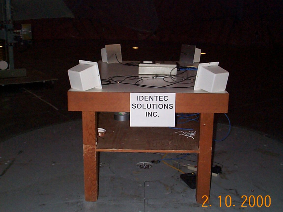
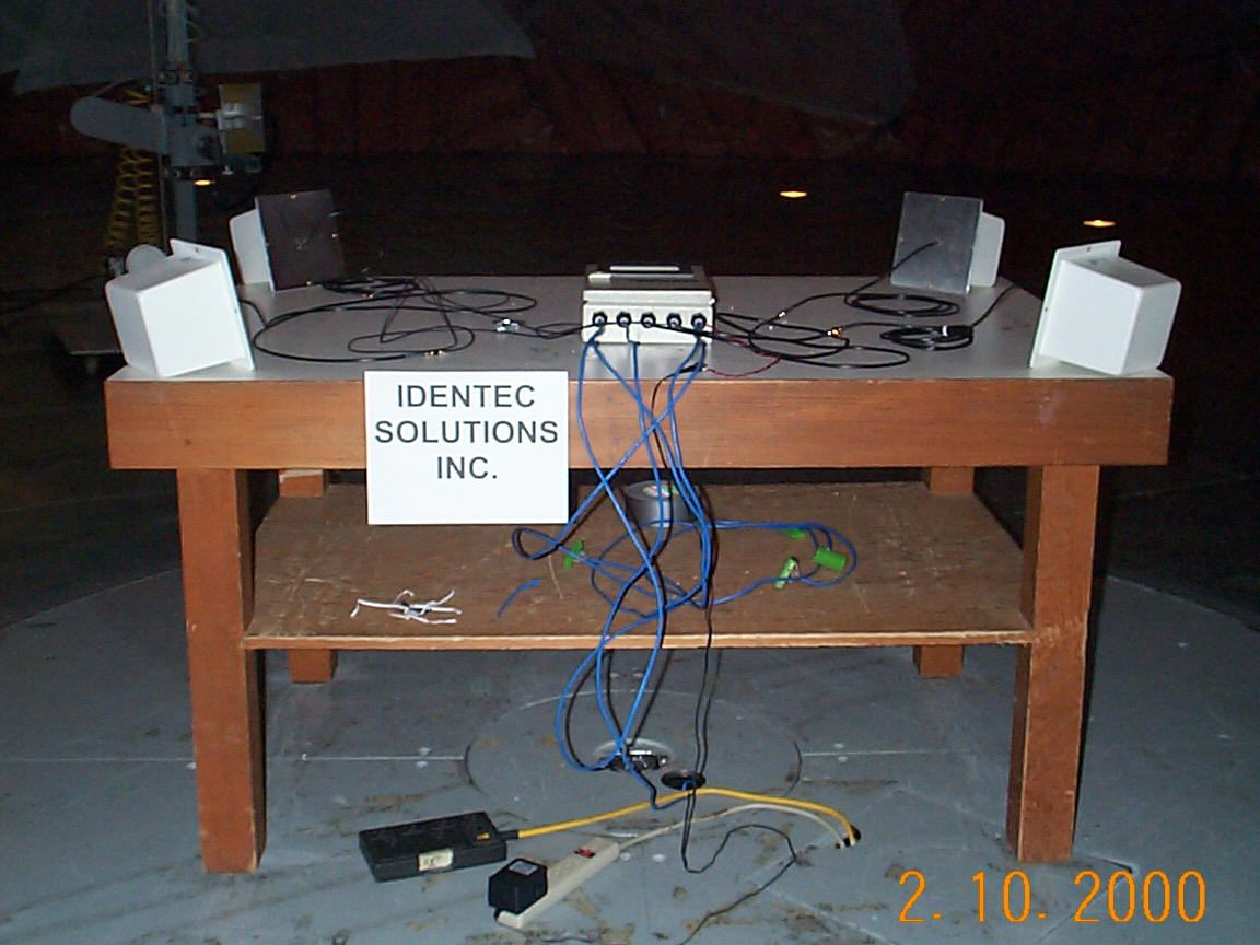
DATE OF ISSUANCE: 08 MAY 2000 REPORT NUMBER: 2000094 FCC ID: OO3-ILR-IPORT PAGE 1 OF 18 Partial reproduction of this document is prohibited without prior written consent of Acme Testing Inc. ACME TESTING INC., 2002 VALLEY HWY, P.O. BOX 3, ACME, WASHINGTON 98220-0003 888-226-3837. REPORT OF MEASUREMENTS PART 15C (15.249) - INTENTIONAL RADIATOR DEVICE: 1 CHANNEL 916.5 MHz 15.249 TRANSMITTER MODEL: I-PORT MANUFACTURER: IDENTEC SOLUTIONS, INC. ADDRESS: SUITE 102, 1860 DAYTON STREET KELOWNA BRITISH COLUMBIA CANADA V1Y 7W6 THE DATA CONTAINED IN THIS REPORT WAS COLLECTED ON 09 & 10 FEBRUARY 2000 AND COMPILED BY: PAUL G. SLAVENS CHIEF EMC ENGINEER WORK ORDER: 32195REV1 DATE OF ISSUANCE: 08 MAY 2000 REPORT NUMBER: 2000094 FCC ID: OO3-ILR-IPORT PAGE 2 OF 18 1. GENERAL........................................................................................................................................................................3 1.1 PURPOSE......................................................................................................................................................................3 1.2 MANUFACTURER..........................................................................................................................................................3 1.3 TEST LOCATION...........................................................................................................................................................3 1.4 TEST PERSONNEL.........................................................................................................................................................3 2. TEST RESULTS SUMMARY.........................................................................................................................................4 3. DESCRIPTION OF EQUIPMENT AND PERIPHERALS...........................................................................................5 3.1 EQUIPMENT UNDER TEST (EUT)..................................................................................................................................5 3.2 EUT PERIPHERALS......................................................................................................................................................5 3.3 DESCRIPTION OF INTERFACE CABLES............................................................................................................................5 3.4 MODE OF OPERATION DURING TESTS...........................................................................................................................5 3.5 MODIFICATIONS REQUIRED FOR COMPLIANCE..............................................................................................................5 4. ANTENNA REQUIREMENT.........................................................................................................................................6 4.1 REGULATION...............................................................................................................................................................6 4.2 RESULT........................................................................................................................................................................6 5. CONDUCTED EMISSIONS TESTS..............................................................................................................................7 5.1 TEST EQUIPMENT.........................................................................................................................................................7 5.2 PURPOSE......................................................................................................................................................................7 5.3 TEST PROCEDURES......................................................................................................................................................7 5.4 TEST RESULTS.............................................................................................................................................................8 6. SINGLE CHANNEL BAND EDGE PLOTS................................................................................................................11 6.1 PURPOSE....................................................................................................................................................................11 6.2 TEST EQUIPMENT.......................................................................................................................................................11 6.3 TEST PLOTS...............................................................................................................................................................12 7. RADIATED EMISSIONS..............................................................................................................................................13 7.1 TEST EQUIPMENT.......................................................................................................................................................13 7.2 REGULATION.............................................................................................................................................................14 7.3 TEST PROCEDURES....................................................................................................................................................15 7.4 TEST RESULTS...........................................................................................................................................................15 8. MISCELLANEOUS COMMENTS AND NOTES.......................................................................................................18 9. LIST OF ATTACHMENTS..........................................................................................................................................18 DATE OF ISSUANCE: 08 MAY 2000 REPORT NUMBER: 2000094 FCC…
Text truncated - open the document above for the full version.
Test Report
DATE OF ISSUANCE: 08 MAY 2000 REPORT NUMBER: 2000094 FCC ID: OO3-ILR-IPORT PAGE 1 OF 18 Partial reproduction of this document is prohibited without prior written consent of Acme Testing Inc. ACME TESTING INC., 2002 VALLEY HWY, P.O. BOX 3, ACME, WASHINGTON 98220-0003 888-226-3837. REPORT OF MEASUREMENTS PART 15C (15.249) - INTENTIONAL RADIATOR DEVICE: 1 CHANNEL 916.5 MHz 15.249 TRANSMITTER MODEL: I-PORT MANUFACTURER: IDENTEC SOLUTIONS, INC. ADDRESS: SUITE 102, 1860 DAYTON STREET KELOWNA BRITISH COLUMBIA CANADA V1Y 7W6 THE DATA CONTAINED IN THIS REPORT WAS COLLECTED ON 09 & 10 FEBRUARY 2000 AND COMPILED BY: PAUL G. SLAVENS CHIEF EMC ENGINEER WORK ORDER: 32195REV1 DATE OF ISSUANCE: 08 MAY 2000 REPORT NUMBER: 2000094 FCC ID: OO3-ILR-IPORT PAGE 2 OF 18 1. GENERAL........................................................................................................................................................................3 1.1 PURPOSE......................................................................................................................................................................3 1.2 MANUFACTURER..........................................................................................................................................................3 1.3 TEST LOCATION...........................................................................................................................................................3 1.4 TEST PERSONNEL.........................................................................................................................................................3 2. TEST RESULTS SUMMARY.........................................................................................................................................4 3. DESCRIPTION OF EQUIPMENT AND PERIPHERALS...........................................................................................5 3.1 EQUIPMENT UNDER TEST (EUT)..................................................................................................................................5 3.2 EUT PERIPHERALS......................................................................................................................................................5 3.3 DESCRIPTION OF INTERFACE CABLES............................................................................................................................5 3.4 MODE OF OPERATION DURING TESTS...........................................................................................................................5 3.5 MODIFICATIONS REQUIRED FOR COMPLIANCE..............................................................................................................5 4. ANTENNA REQUIREMENT.........................................................................................................................................6 4.1 REGULATION...............................................................................................................................................................6 4.2 RESULT........................................................................................................................................................................6 5. CONDUCTED EMISSIONS TESTS..............................................................................................................................7 5.1 TEST EQUIPMENT.........................................................................................................................................................7 5.2 PURPOSE......................................................................................................................................................................7 5.3 TEST PROCEDURES......................................................................................................................................................7 5.4 TEST RESULTS.............................................................................................................................................................8 6. SINGLE CHANNEL BAND EDGE PLOTS................................................................................................................11 6.1 PURPOSE....................................................................................................................................................................11 6.2 TEST EQUIPMENT.......................................................................................................................................................11 6.3 TEST PLOTS...............................................................................................................................................................12 7. RADIATED EMISSIONS..............................................................................................................................................13 7.1 TEST EQUIPMENT.......................................................................................................................................................13 7.2 REGULATION.............................................................................................................................................................14 7.3 TEST PROCEDURES....................................................................................................................................................15 7.4 TEST RESULTS...........................................................................................................................................................15 8. MISCELLANEOUS COMMENTS AND NOTES.......................................................................................................18 9. LIST OF ATTACHMENTS..........................................................................................................................................18 DATE OF ISSUANCE: 08 MAY 2000 REPORT NUMBER: 2000094 FCC…
Text truncated - open the document above for the full version.
Test Report
DATE OF ISSUANCE: 08 MAY 2000 REPORT NUMBER: 2000094 FCC ID: OO3-ILR-IPORT PAGE 11 OF 18 6. Single Channel Band Edge Plots Test Requirement: FCC CFR47, Part 15C, 15.249 Test Procedure: ANSI C63.4:1992 6.1 Purpose The purpose of these plots is to show compliance of the radiated emissions at the band edge of the 902 – 928 MHz band. 6.2 Test Equipment ⇒ Spectrum Analyzer (yellow): Hewlett-Packard 8566B, Serial Number 2403A06519, Calibrated: 7 January 2000, Calibration due Date: 7 January 2001 ⇒ RF Preselector (yellow): Hewlett-Packard 85685A, Serial Number 2926A00971, Calibrated: 17 March 2000, Calibration due Date: 17 March 2001 ⇒ Quasi Peak Adapter (yellow): Hewlett-Packard 85650A, Serial Number 2521A-00689, Calibrated: 19 November 1999, Calibration due Date: 19 November 2000 ⇒ Broadband Biconical Antenna (red) (20 MHz to 200 MHz): EMCO 3110, Serial Numbe…
Text truncated - open the document above for the full version.
Contact Information
Applicant
Barry Allen(VP Engineering)
Technical Contact
Acme TestingPaul G Slavens
[email protected]360 595-2785
2002 Valley Highway · Acme, Washington · United States
Non-Technical Contact
Acme TestingDesiree R Patterson
[email protected]360 595-2785
Technical Specifications
| # | Rule Parts | Frequency Range | Power Output |
|---|---|---|---|
| 1 | 15C | 916.5 MHz - 916.5 MHz | - |
Other Applications from Identec Solutions, Inc.

O2E-ILR-IM2
Jan 28, 2008Position Marker
Equipment Class
DCD - Part 15 Low Power Transmitter Below 1705 kHz
O2E-ILR-IM3
Jul 05, 2007Position Marker
Equipment Class
DCD - Part 15 Low Power Transmitter Below 1705 kHz
O2E-ILR-IP3NA
Jan 17, 2006i-Port3
Equipment Class
FDS - Part 15 Field Disturbance Sensor
O2E-ILR-ICARDIII
May 09, 2004Type II PCMCIA Mobile RFID Reader
Equipment Class
DXX - Part 15 Low Power Communication Device Transmitter
O2E-ILR-IPORT3
Nov 12, 2003transmits and receives data for identification
Equipment Class
FDS - Part 15 Field Disturbance Sensor