O2J-SCRT-1-49TSCRT
Airspan Communications Limited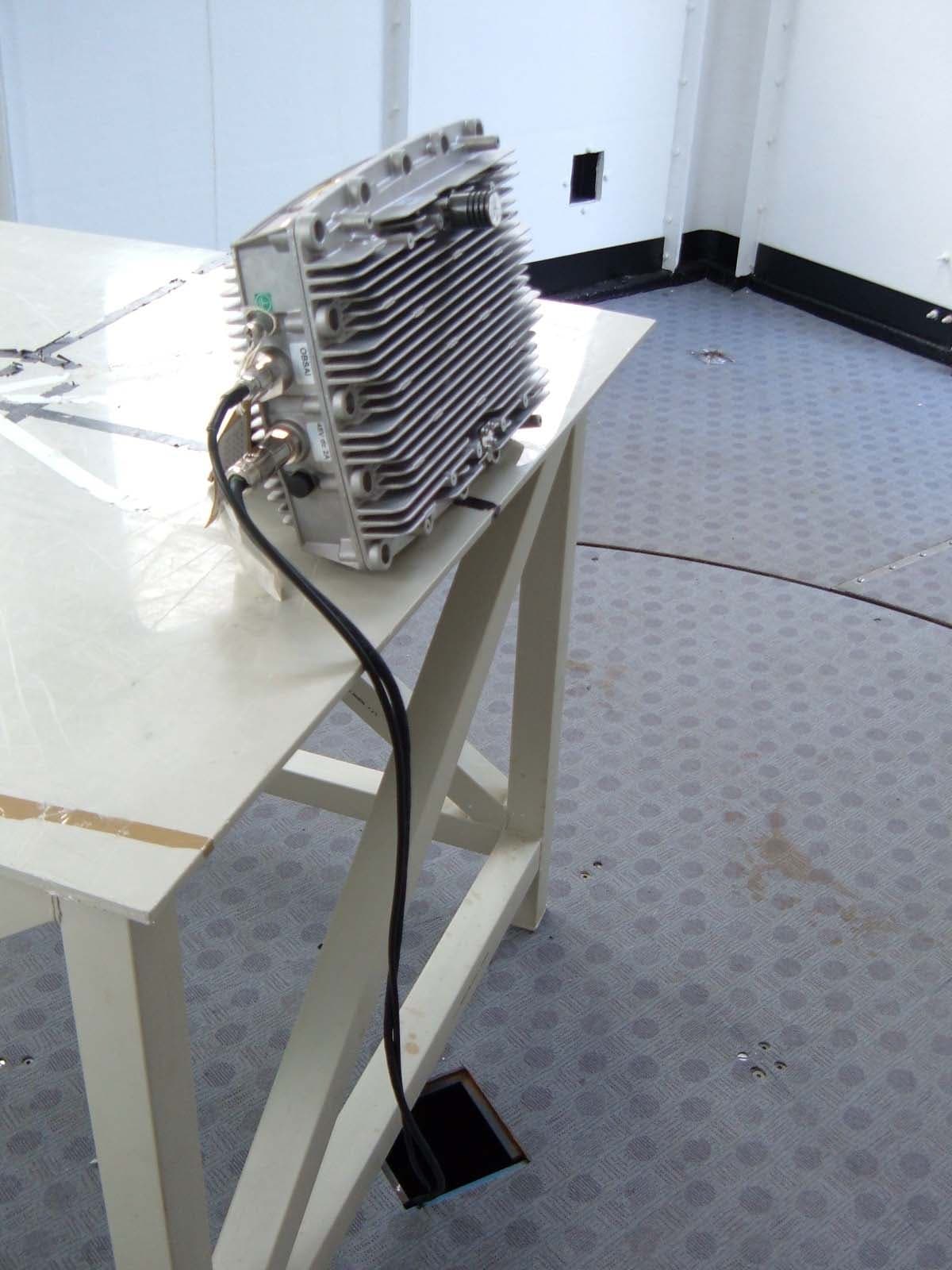
Click to zoom
Application Details
- Equipment Class
- TNB - Licensed Non-Broadcast Station Transmitter
- Date of Grant
- Mar 28, 2006
- Application Purpose
- Original Equipment
- Date of Application
- Mar 28, 2006
- Equipment Note
- SCRT
- Frequency Range
- 4942.50000000 - 4987.50000000
- Country
- United Kingdom
Documents & Files
Document Text
Text extracted from the exhibit documents filed with the FCC. Open a document above to read the original.
Users Manual
IP-based Broadband Wireless Access (BWA) System 605-0000-716 Rev 02 MicroMAX System OverView User's Guide The Innovation Behind Broadband Wireless Connecting the World iii Table Of Contents System Overview...........................................................................................................1 MicroMAX-SDR Base Station Operation ...........................................................................1 MicroMAX-SDR Architecture Overview ............................................................................2 SDR Baseband Sub-system:.......................................................................................2 Single Channel Radio Transceiver (SCRT) RF Subsystem Module: ....................................2 External Antennas: ...................................................................................................2 MicroMAX-SDR Antenna Options....................................................................................2 Technical Overview ........................................................................................................3 Employed Multi-path and Delay-Spread Mitigation Techniques ...........................................3 Spectral Efficiency.......................................................................................................4 Adaptive Modulation ....................................................................................................4 Burst Profiling.............................................................................................................4 STC ..........................................................................................................................4 MRC ..........................................................................................................................4 Software Defined Radio using picoChip ...........................................................................4 Transport Overview........................................................................................................6 PHY and MAC Layers....................................................................................................6 Security Overview..........................................................................................................7 Security.....................................................................................................................7 System Management......................................................................................................8 Management Options ...................................................................................................8 Service Provisioning within Netspan ...............................................................................8 QOS Overview............................................................................................................. 10 Applications of QoS within AS.MAX Networks................................................................. 10 QoS Utilisation Overview ............................................................................................ 10 Single Channel Radio Transceiver (SCRT) ........................................................................ 11 Physical ................................................................................................................... 11 Interfaces ................................................................................................................ 11 Software Defined Radio (SDR) ....................................................................................... 12 Physical ................................................................................................................... 12 Interfaces ................................................................................................................ 12 System Installation ...................................................................................................... 15 Typical Layout .......................................................................................................... 15 Installing the MicroMAX-SDR Enclosure ........................................................................ 15 Tools Required ....................................................................................................... 15 Parts Required ....................................................................................................... 16 MicroMAX-SDR Mounting Plate .................................................................................... 16 Mounting the MicroMAX-SDR....................................................................................... 17 Mounting the SCRT.................................................................................................... 17 SDR Connections ......................................................................................................... 18 Power Input ............................................................................................................. 18 605-0000-716 MicroMAX User Guide Rev 02 iv Power Output ........................................................................................................... 18 Optic Interface.......................................................................................................... 18 Ethernet .................................................................................................................. 18 Assembly of Connector............................................................................................ 18 SCRT Connections........................................................................................................ 20 Power Input ............................................................................................................. 20 Optic Interface.........................................................................…
Text truncated - open the document above for the full version.
ID Label/Location Info
SCRT label and position
Operational Description
Technical Overview Employed Multi-path and Delay-Spread Mitigation Techniques MicroMAX-SDR utilizes the cyclic prefix duration included in 802.16 to cater for delay spread and effects of multi-path. Guard ratios of between ¼ and 1/32 are programmable resulting in peak delay spread immunity between 2us and 16us respectively for a 3.5MHz channel bandwidth. 802.16e standard will introduce the OFDMA access method. This allows the system to restrict certain tones within the OFDM waveform to any individual subscriber unit. By avoiding null traffic channels due to deep fading and/or narrowband interference, the system provides optimum performance in a multi- path environment. OFDMA enjoys the finest granularity and better uplink power efficiency than traditional OFDM/TDMA systems. Radio resource allocation is implemented at the base station and users are notified of the channel assignment through a multiple access protocol. MicroMAX-SDR is upgradeable to 802.16e via a software upgrade. Benefits of using Orthogonal Frequency Division Multiple Access In the uplink each subscriber is assigned 1 to 59 sub-channels. when assigned sub-channels, a subscriber concentrates its power on these sub-channels. It solves the Multipath problem and reduces Multipath Interference It has high Spectral efficiency It supports smart antenna technology: Smart antennas provide greater capacity and performance benefits than standard antennas because they can be used to customize and fine- tune antenna coverage patterns that match the traffic conditions in a wireless network or that are better suited for complex radio frequency (RF) environments. Furthermore, smart antennas provide maximum flexibility by enabling wireless network operators to change antenna patterns to adjust to the changing traffic or RF conditions in the network. o RX/TX antenna diversity o Space Time Coding (STC) It is an efficient modulation o QPSK, QAM16, QAM64 per sub carrier o FEC rates ranging from 1/2 to 3/4 o Guard intervals of 1/32, 1/16, 1/8 and 1/4 Supports adaptive modulation on a per subchannel basis The efficient use of pilots minimizes requirement for preambles for channel estimation External, narrow band interference is rejected through frequency domain processing External, burst interference is rejected by virtue of the OFDMA symbol length and the per sub- channel interleaving Inter-cell interference is mitigated by use different sub-carriers in sub-channels Spectral Efficiency The network spectral efficiencies for MicroMAX-SDR, MicroMAX-SDR and HiperMAX assuming 3.5MHz FDD channels are as follows: Gross Throughput (Mb/s) Mod/FEC Downlink Uplink Occupied Bandwidth (Mhz) Spectral Efficiency (b/s/Hz) per RF Channel 64QAM3/4 13.1 13.1 3.5 3.7 64QAM1/2 11.5 11.6 3.5 3.3 16QAM3/4 8.7 8.7 3.5 2.5 16QAM1/2 5.8 5.8 3.5 1.7 QPSK3/4 4.4 4.4 3.5 1.3 QPSK1/2 2.9 2.9 3.5 0.8 BPSK1/2 1.4 1.4 3.5 0.4 Note: Figures above are based on Gross throughput. Maximum achievable net throughput is in the region of 85% of gross downlink throughput and 75% of gross uplink throughput which is required to accommodate overhead including Pre-amble, DL&UL Maps, DLFP and Mid-ambles. Adaptive Modulation Adaptive modulation techniques, for maximizing system throughput by monitoring link quality and selecting the highest usable adaptive burst profile, are used throughout the MicroMAX-SDR product range. Within each burst, data transmitted over the air is padded with redundant information to make it more resistant to errors introduced by interference. The coding rate is the ratio of user-data to the total data transmitted (which includes redundant error correction data. Protocol features allow for adaptive modulation to be employed in both downlink and uplink. Modulations ranging BPSK 1/2 to 64QAM 3/4 may be employed. Burst Profiling All MicroMAX-SDR Base stations, operating using FDD or TDD in the downlink and uplink support burst profiles which are adaptive on a per terminal basis. Burst profiles are used to define modulation and FEC levels using the DCD and UCD messaging schemes and are invoked through downlink and uplink MAP messaging. RF link control functions within the Base station and the ST continuously monitor receiver SNR and adapt modulation accordingly. STC Space Time Coding is a method of transmit diversity using two antennas, is used within the MicroMAX- SDR product. This mode may be used to improve link robustness. MRC Maximal-ratio combining is a form of diversity combiner in which (a) the signals from each channel are added together, (b) the gain of each channel is adjusted to ensure each channel is proportional to the rms signal level in each channel and inversely proportional to the mean square noise level in that channel, and (c) the same proportionality constant is used for all channels. Software Defined Radio using picoChip MicroMAX-SDR Base stations are fully upgradeable and future-proof due to the use of picoChip technology. PicoChip provides high performance processing arrays which have been optimized for use within the wireless industry. This enables the complete radio and digital signal processing functions to be soft-defined within devices which have replaced the need to incorporate inflexible FPGA and ASIC silicon. PicoChip devices are fully reprogrammable to allow the 802.16 PHY to be completely upgraded, through the use of a simple software download, as the WiMAX standard evolves. Using picoChip, the ASMAX MicroMAX-SDR Base stations will always remain compliant with this emerging standard. Key benefits of using picoChip within the MicroMAX-SDR Base stations: Software defined: Fully Scalable & Future Proof Full support for 802.16-2004 (256 OFDM PHY) Upgradeable to 802.16e to support hand held devices Support for 1X scalable PHY & OFDMA FDD or TDD; 3.5MHz / 7MHz / 10MHz Software defined RF (industry standard OBSAI RP3-01 interface) Advanced feature options: Smart antennas & diversity, SDMA
Parts List/Tune Up Info
Transmit power is set using the Netspan management software. The maximum TXpower is capped in the SCRT firmware at 22.7dBm – this is the level used during testing of the 10MHz channels For 5MHz channel operation, a maximum TX level of 21 dBm shall be entered in the TX Power (custom) box
Test Report
TEST REPORT FROM RFI GLOBAL SERVICES LTD Test of: Airspan Communications Ltd. SCRT (Transceiver) To: FCC Part 90 in accordance to MicroMAX-SDR & SCRT FCC Test Plan Document Reference: 005-8300-012 28 February 2006 Rev. B Test Report Serial No: RFI/MPTE3/RP47795JD02A Supersedes Test Report Serial No: RFI/MPTE2/RP47795JD02A This Test Report Is Issued Under The Authority Of Andrew Brown, Operations Manager: pp Tested By: Fara Razally pp Checked By: Michael Derby pp Report Copy No: PDF01 Issue Date: 21 June 2006 Test Dates: 20 February 2006 to 09 March 2006 and 20 June 2006 This report is issued in Adobe Acrobat portable document format (PDF). It is only a valid copy of the report if it is being viewed in PDF format with the following security options not allowed: Changing the document, Selecting text and graphics, Adding or changing notes and form fields. This report may be copied in full. The results in this report apply only to the sample(s) tested. RFI GLOBAL SERVICES LTD TEST REPORT S.No. RFI/MPTE3/RP47795JD02A Page: 2 of 58 Issue Date: 21 June 2006 Test of: Airspan Communications Ltd. SCRT (Transceiver) To: FCC Part 90 in accordance to MicroMAX-SDR & SCRT FCC Test Plan Document Reference: 005-8300-012 28 February 2006 Rev. B This page has been left intentionally blank. RFI GLOBAL SERVICES LTD TEST REPORT S.No. RFI/MPTE3/RP47795JD02A Page: 3 of 58 Issue Date: 21 June 2006 Test of: Airspan Communications Ltd. SCRT (Transceiver) To: FCC Part 90 in accordance to MicroMAX-SDR & SCRT FCC Test Plan Document Reference: 005-8300-012 28 February 2006 Rev. B Table of Contents 1. Client Information ............................................................................................................................4 2. Equipment Under Test (EUT) ..........................................................................................................5 3. Test Specification, Methods and Procedures ...............................................................................8 4. Deviations from the Test Specification..........................................................................................9 5. Operation of the EUT During Testing...........................................................................................10 6. Summary of Test Results ..............................................................................................................11 7. Measurements, Examinations and Derived Results ...................................................................12 8. Measurement Uncertainty .............................................................................................................44 9. Measurement Methods ..................................................................................................................45 Appendix 1. Test Equipment Used ...................................................................................................54 Appendix 2. Test Configuration Drawings.......................................................................................55 Test Report Serial No: RFI/MPTE3/RP47795JD02A Supersedes Test Report Serial No: RFI/MPTE2/RP47795JD02A RFI GLOBAL SERVICES LTD TEST REPORT S.No. RFI/MPTE3/RP47795JD02A Page: 4 of 58 Issue Date: 21 June 2006 Test of: Airspan Communications Ltd. SCRT (Transceiver) To: FCC Part 90 in accordance to MicroMAX-SDR & SCRT FCC Test Plan Document Reference: 005-8300-012 28 February 2006 Rev. B 1. Client Information Company Name: Airspan Communications Ltd. Address: Cambridge House Oxford Road Uxbridge UB8 1UN Contact Name: Charles Blackham RFI GLOBAL SERVICES LTD TEST REPORT S.No. RFI/MPTE3/RP47795JD02A Page: 5 of 58 Issue Date: 21 June 2006 Test of: Airspan Communications Ltd. SCRT (Transceiver) To: FCC Part 90 in accordance to MicroMAX-SDR & SCRT FCC Test Plan Document Reference: 005-8300-012 28 February 2006 Rev. B 2. Equipment Under Test (EUT) The following information (with the exception of the Date of Receipt) has been supplied by the client: 2.1. Identification of Equipment Under Test (EUT) Brand Name: Airspan Communications Ltd (Single Channel Radio Transceiver) Model Name or Number: Single Channel Radio Transceiver Unique Type Identification: SCRT-1-4.9T-1 Serial Number: 35628 Hardware Revision: 605-0010-507 FCC ID O2J-SCRT-1-49T Country of Manufacture: UK Date of Receipt: 20 February 2006 2.2. Accessories The following accessories were supplied with the EUT: Description: SDR Brand Name: Airspan Communications Ltd Model Name or Number: SDR-M1 Serial Number: 35764 Hardware Revision: 503-0030-030 Cable Length and Type: 3m, Weatherproof Fibre Optic Proprietary Connection 3m 2-core DC power feed Connected to Port: OBSAI Port and DC port 2.3. Description of EUT The equipment under test is an IEE802.16-2004 WiMAX compliant broadband Wireless Access System base station providing point-to-multipoint data communication. 2.4. Modifications Incorporated in the EUT During the course of testing the EUT was not modified. RFI GLOBAL SERVICES LTD TEST REPORT S.No. RFI/MPTE3/RP47795JD02A Page: 6 of 58 Issue Date: 21 June 2006 Test of: Airspan Communications Ltd. SCRT (Transceiver) To: FCC Part 90 in accordance to MicroMAX-SDR & SCRT FCC Test Plan Document Reference: 005-8300-012 28 February 2006 Rev. B 2.5. Additional Information Related to Testing Power Supply Requirement: DC Supply of 48V via the SDR, which is connected to the 115 V 60 Hz AC Mains supply. Intended Operating Environment: Commercial and Light Industry Equipment Category: Fixed Point-to-Multipoint Type of Unit: Base Station (Fixed Use) Channel Spacing: 5 MHz and 10 MHz Highest Unintentionally Generated Frequency: 768 MHz Highest Fundamental Frequency: 4990.0 MHz Occupied Bandwidth: 5 MHz Channel: 4.629 MHz 10 MHz Channel: 9.198 MHz For 5 MHz Channel Spacing: Transmit Frequency Range: 4942.5 MHz to 4987.5 MHz Channel ID Channel Number Channel Frequency (MHz) Bottom 1 4942.5 Transmit Channels Tested: Top 200 4987.5 For 10 MHz C…
Text truncated - open the document above for the full version.
Contact Information
Applicant
Mike Livingstone(VP Engineering)
Test Firm
UL VS LtdDarren Rust
Technical Specifications
| # | Rule Parts | Frequency Range | Power Output | Emission | Tolerance |
|---|---|---|---|---|---|
| 2 | 90.21 | 4.94 GHz - 4.99 GHz | 479.00 mW | 5M0D1D | 8 ppm |
Other Applications from Airspan Communications Limited
O2J-CBATG
Sep 03, 20264G/5G Small Cell Transportable Base Station used for testing ATG network installations.
Equipment Class
TNB - Licensed Non-Broadcast Station Transmitter
O2J-375AS
Sep 16, 2013Airsynergy Compact Outdoor Pico Base Station
Equipment Class
TNB - Licensed Non-Broadcast Station Transmitter
O2J-235AS
Sep 29, 2011Airsynergy WiMAX Basestation
Equipment Class
TNB - Licensed Non-Broadcast Station Transmitter
O2J-365AS
Sep 13, 2011Airsynergy WiMAX Basestation
Equipment Class
TNB - Licensed Non-Broadcast Station Transmitter
O2J-070T
May 05, 2010700 MHz SCRT
Equipment Class
TNB - Licensed Non-Broadcast Station Transmitter