O2J-STODU-PCSSubscriber Terminal
Airspan Communications Limited
Click to zoom
Application Details
- Equipment Class
- PCB - PCS Licensed Transmitter
- Date of Grant
- Jul 04, 2004
- Application Purpose
- Original Equipment
- Date of Application
- Jul 04, 2004
- Equipment Note
- Subscriber Terminal
- Frequency Range
- 1850.00000000 - 1910.00000000
- Country
- United Kingdom
Documents & Files
Document Text
Text extracted from the exhibit documents filed with the FCC. Open a document above to read the original.
Users Manual
605-0000-595 Subscriber Terminal Installation and Commissioning i Table Of Contents AS4000 STs.....................................................................................................................1 AS4000 Subscriber Terminal Overview.......................................................................1 Subscriber Terminal Products.....................................................................................6 The B Series Service Interface Unit.............................................................................8 The L Series Service Interface Unit.............................................................................9 The M Series Modular Service Interface Unit.............................................................10 The N Series Service Interface Unit...........................................................................11 The P Series Subscriber Terminal.............................................................................12 The R Series Residential Service Interface Unit(Plastic Case)....................................14 The R Series Residential Service Interface Unit (Metal Case).....................................15 The S Series Sub Unit Service Interface Unit.............................................................17 V Series..................................................................................................................18 W Series.................................................................................................................19 Specifications..........................................................................................................21 AS4020 STs...................................................................................................................23 AS4020 Subscriber Terminal Overview.....................................................................23 AS4020 Subscriber Terminal Products......................................................................26 Type 42......................................................................................................................27 Type 42 Overview....................................................................................................27 The P Series Subscriber Terminal.............................................................................30 W Series.................................................................................................................31 V Series..................................................................................................................33 Specifications..........................................................................................................35 Installation......................................................................................................................37 Pre-installation.........................................................................................................37 Installation Steps.....................................................................................................38 Preparation.................................................................................................................40 Site Selection..........................................................................................................40 Unpacking and Inspection........................................................................................43 Required Tools and equipment.................................................................................44 Installing Outdoor Unit.................................................................................................46 Installing the Wall Mount Outdoor Unit Using Bracket 605-0010-279/280.....................46 Installing the Outdoor Unit Using Bracket 605-0010-283............................................52 Installing The Pole Mount Outdoor Unit .....................................................................57 Installing the IF Unit for External Antenna..................................................................60 Installing Drop Cable...................................................................................................63 Drop Cable Installation.............................................................................................63 Drop Cable Termination Using Crimp Type Connectors..............................................66 Drop Cable Termination Snap and Seal Connectors...................................................68 Drop Cable Termination using RG11 Snap and Seal Connectors................................69 Installing PSUs............................................................................................................70 Type 6 PSU.............................................................................................................70 Type 7 PSU.............................................................................................................71 Installing AS4000 SIUs................................................................................................74 Installing B Series SIU..............................................................................................74 Configuring the S-Bus..................................................................................................76 Installing L Series SIU..............................................................................................77 Installing the M Series Module Enclosure..................................................................81 Installing N Series SIU..............................................................................................97 Installing P Series SIUs..........................................................................................101 Installing The R series Service Interface Unit and PSU..............................................106 Installing R Se…
Text truncated - open the document above for the full version.
ID Label/Location Info
FCC ID: O2J-STODU-PCS
Internal Photos
Type 42 top-side with can Type 42 top-side without can Type 42 bottom-side with can Type 42 bottom-side without can Type 42 SIU
Operational Description
Airspan Networks Inc Cambridge House · Oxford Road Uxbridge · Middlesex · UB8 1UN · U.K. Telephone: +44 (0) 1895 467 100 Fax: +44 (0) 1895 467 101 Email: [email protected] Website: http://www.airspan.com Broadband Wireless Access System Description Version 2.4 February 2004 AS4020 System Description V2.4 Airspan Networks Inc. – CONFIDENTIAL Page 2 Contents 1 EXECUTIVE SUMMARY ................................................................................................................. 4 2 PRODUCT OVERVIEW................................................................................................................... 7 2.1 AS4020 Service Capabilities .................................................................................................................... 8 2.2 Market Segments Addressed ................................................................................................................... 9 2.3 System Architecture ............................................................................................................................... 10 2.4 System Interfaces .................................................................................................................................... 21 2.5 Future Product Enhancement ............................................................................................................... 26 3 DEPLOYMENT, CONFIGURATIONS AND CAPACITY............................................................... 27 3.1 Airspan’s Deployments .......................................................................................................................... 27 3.2 Type Approvals ....................................................................................................................................... 27 3.3 AS4020 Frequency Re-use...................................................................................................................... 28 4 SYSTEM FEATURES AND SPECIFICATIONS ........................................................................... 30 4.1 Conformance to Standards .................................................................................................................... 30 4.2 Frequency Ranges Supported................................................................................................................ 30 4.3 Radio Link Budget.................................................................................................................................. 31 4.4 Speech Coding ......................................................................................................................................... 31 4.5 System Security ....................................................................................................................................... 32 4.6 Subscriber Auto Connect ....................................................................................................................... 32 4.7 System Capacity (AS4020) ..................................................................................................................... 33 APPENDIX A: FREQUENCY PLANS .................................................................................................. 35 AS4020 System Description V2.4 Airspan Networks Inc. – CONFIDENTIAL Page 3 APPENDIX B: COMPLIANCE WITH STANDARDS AND REGULATIONS ....................................... 42 APPENDIX C: ISO9001 CERTIFICATE............................................................................................... 44 APPENDIX D: RF PLANNING ............................................................................................................. 45 GLOSSARY .......................................................................................................................................... 47 AS4020 System Description V2.4 Airspan Networks Inc. – CONFIDENTIAL Page 4 1 Executive Summary Airspan Network’s AS4020 system is a sophisticated wireless point to multipoint fixed Broadband Wireless Access system designed to deliver High Speed Internet connections and Telephony Services. AS4020 is an evolution of Airspan Network’s field proven AS4000 Platform. AS4020 continues to offer high quality, high capacity voice services, but offers significant efficiency improvements over AS4000 for IP based services. AS4020 shares a large number of common components with AS4000, and can therefore be deployed separately, or as part of the same Base Station. This minimises the cost of upgrading an existing AS4000 system. AS4020 is designed for Network Operators and Internet Service Providers who wish to offer premium services; the system is ideal as either an enhancement to existing network (Wired or Wireless), or as a platform to deploy a completely new network. AS4020 operates in various licensed frequency bands from 1.8 to 3.6GHz ensuring the maximum coverage of fixed access radio spectrum available to operators today. AS4020 can be described as a “flexible access tool” for network operators to provide a variety of services to their end-user customers. Significantly, they are able to provide services that are the same quality and performance as wired services, by supporting transparent connections to the operator’s network. The services offered by an Airspan AS4020 system will be perceived by end-users as a Wireless DSL solution. It provides customers with combinations of Voice Telephony and an always-on high speed Internet connections, very similar to capabilities of wired DSL solutions. AS4020 System Description V2.4 Airspan Networks Inc. – CONFIDENTIAL Page 5 Each AS4020 system comprises: • Subscriber Terminals (STs), which offer a wide range of service combinations on a single customer interface unit, including data only terminals, integrated data and voice terminals, and voice only terminals. Voice only and Integrated Voice / Data Terminals can have up to 4 voice lines. • Central Terminals (CTs), Ai…
Text truncated - open the document above for the full version.
Parts List/Tune Up Info
Printed Documentation 144 Set RX Sensitivity without a DACU Tools and equipment needed. Item Description Recommended Model Quantity 1 Digital Multimeter Fluke 77 1 2 ST Test Unit, SIU with Modified Antenna at appropriate band 1 3 30dB Attenuators; 5W Mini Circuits: BN-N30W5 2 4 30dB Attenuators; 2W M/A-COM:2082 6044 30:2W 2 5 Two Way Power Divider Mini Circuits: ZAPD-4-S 1 6 50 ohm Termination 10W Arra N9510 1 7 Adaptor; N-SMA Huber & Suhner 33N-SMA-50-1 1 8 Adaptor; N-SMA Huber & Suhner 31N-SMA-50-1 1 9 Huber & Suhner Sucoflex 104; 0.5m 2 10 Co-ax Cables Huber & Suhner Sucoflex 104; 4.0m 1 11 Cable SMA-MCX Huber & Suhner 30-05918-10 1 12 RF Power Meter Marconi 6970 1 13 Power Sensor Marconi/RFI 6970&5 6932/900 1 RX Sensitivity (Test 6) The RX sensitivity is set according to the required CT RX level. It is important to note that the lower the modulation rate the further the geographical spread. For maximum range the AS4020 should use QPSK 1/2. Higher data rates may be achieved using higher orders of modulation but the range will lessen as the modulation rate increase. This level is determined as part of the planning function and takes into consideration the highest modulation rate to be offered and the noise floor predicted in the planning stage. The RX Level is set dependant on the highest operational modulation rate as follows. By undertaking an appropriate level of RF planning the level is optimised in order to balance uplink data rate and system range. Typical levels are shown below for two network configuration scenarios: For networks where only a single RF Channel is operating, or only adjacent + one RF Channels are used (no co or adjacent channel interference), the following CT Rx levels apply: Rx Level (dBm / RW) Modulation Code Rate Below 3GHz Above 3GHz Session ids for LAT TE command in Mode 3 QPSK 1/2 -105 dBm -103dBm 58 or 59 QPSK 3/4 -103 dBm -101dBm 56 or 57 16QAM 1/2 -97 dBm -95dBm 54 or 55 16QAM 3/4 -93 dBm (see note 1) -91dBm 52 or 53 64QAM 3/4 Not supported on the uplink Table 1 Note 1: Note, 16QAM ¾ is only supported on the uplink with up to 7RW Codes Active. Setup and Test 145 For networks where co or adjacent frequencies are reused to provide cellular type network coverage with limited available spectrum (ie. A relatively high level of co and adjacent channel interference), the following CT Rx levels apply: Rx Level (dBm / RW) Modulation Code Rate Below 3GHz Above 3GHz Session ids for LAT TE command in Mode 3 QPSK 1/2 -103 dBm -100dBm 58 or 59 QPSK 3/4 -101 dBm -98dBm 56 or 57 16QAM 1/2 -94 dBm -92dBm 54 or 55 16QAM 3/4 -90 dBm (see note 1) -88dBm 52 or 53 64QAM 3/4 Not supported on the uplink Table 1a 1. To set the receive sensitivity, first set up a test network for the band under test as shown below. The figure below shows a typical test setup with test equipment connected directly to the outputs of the DIP/LNA and DIP/LNA2 as would be the case for systems without a RF coupler. Test Set-up 2. Zero power meter. Calibrate and apply measurement offset for operational frequency if applicable. 3. On the AS4020 go to Top Menu >Setup Menu >RF Menu>RX Sensitivity. Set RX to 2500 4. Put AS4020 Shelf into test mode Off and then into test mode 3. (from AS4020 menu select Setup Menu/RF Menu/RF Commissioning) 5. Configure the Test SIU using AS7020STMON according to modem shelf properties to the correct frequency, PN code and ID number prior to entering test mode. The commissioning procedure described in this document is not restricted to any particular RF channel or PN code. However the user should make sure that both the CT and ST are programmed with identical RF channel and PN code. If the frequency can be entered using STMON then the FP command in the step 12 is not necessary) 6. Measure and calibrate the loss of all components shown in the diagram above. To measure the losses of components use the TX output as a reference source. Measure the TX output and place figure in table below.. Connect each component in Printed Documentation 146 turn between the TX output and the power meter and measure the loss added as the component is inserted. Measure (1)A-B, (2)B-C, (3)C-D and (7)D-E. 7. Calculate and enter values in calibration chart for the relevant frequency. RF Channel No: Ref TX output A-B Atten.(1) B-C Atten.(2) RF Section C-D Atten.(3) Sub Total (4) 1+2+3 Required CT RX Level (5) see table 1 ST TX Power (6)=4+5 RF Section D-E Atten (7) Power Meter (8) = 6-7 8. Calculate/determine overall path loss and required ST output power and hence required power meter reading. 9. Connect cables as per diagram above. Try to ensure that the network is set to reduce the amount of radiated pick up. To ensure that it is the receive path that is being measured and not pickup place an attenuator (6dB) into the network and check that the meter falls by a corresponding amount. If it fails to do so additional screening of the test network is probably required. 10. Connect a terminal emulator to the ST. 11. Make the test ST transmit by sending the following LAT commands from a terminal emulator connected to the ST TE<space> 0<space> 4<space> 59 (this code sets the uplink modulation rate for the ST see table 1) FP <space>channel number (in decimal) W<space> 0400003C 12. The terminal emulator should receive 0000000B for the uplink if the ST has acquired a link. 13. On the AS4020 go to Top Menu >Setup Menu >RF Menu>RX Sensitivity 14. Set RX gain by increasing/decreasing the value of RX sensitivity to achieve required ST o/p level as calculated in step 8 for the required RX Level. 15. Record ST o/p level and value set. Link Check 9. When the link has successfully acquired enable the equalizer by typing the following LAT commands ADE 1 10 (this enables the downlink channel equalizer and it should converge within 10 seconds) ADS (this command displays the equalizer stats). When the equalizer is adapting the stat reports Enabled = 1 Converged = 0 When the equalizer is adapting the stat reports Enable…
Text truncated - open the document above for the full version.
Test Report
Radio Frequency Investigation Ltd, Ewhurst Park, Ramsdell, Basingstoke, Hampshire, RG26 5RQ, ENGLAND. Tel: +44 (0) 1256 851193 Fax: +44 (0) 1256 851192 Registered in England, No. 211 7901. Registered Office: Ewhurst Park, Ramsdell, Basingstoke, Hampshire RG26 5RQ TEST REPORT FROM RADIO FREQUENCY INVESTIGATION LTD. Test Of: Airspan Communications. Subscriber Terminal - 1054 ST Antenna To: FCC Part 24 Test Report Serial No: RFI/MPTE1/RP46299JD02B This Test Report Is Issued Under The Authority Of Richard Jacklin, Operations Director: pp Checked By: Nigel Davison pp Tested By: Adam Miller Release Version No: PDF01 Issue Date: 01 July 2004 Test Dates: 01 June 2004 to 17 June 2004 This report is issued in Adobe Acrobat portable document format (PDF). It is only a valid copy of the report if it is being viewed in PDF format with the following security options not allowed: Changing the document, Selecting text and graphics, Adding or changing notes and form fields. Furthermore, the date of creation must match the issue date stated above. This report may be copied in full. The results in this report apply only to the sample(s) tested. RADIO FREQUENCY INVESTIGATION LTD TEST REPORT S.No. RFI/MPTE1/RP46299JD02B Operations Department Page 2 of 56 Issue Date: 01 July 2004 Test Of: Airspan Communications. Subscriber Terminal - 1054 ST Antenna To: FCC Part 24 This page has been left intentionally blank. RADIO FREQUENCY INVESTIGATION LTD TEST REPORT S.No. RFI/MPTE1/RP46299JD02B Operations Department Page 3 of 56 Issue Date: 01 July 2004 Test Of: Airspan Communications. Subscriber Terminal - 1054 ST Antenna To: FCC Part 24 Table of Contents 1. Client Information ............................................................................................................. 4 2. Equipment Under Test (EUT) ........................................................................................... 5 3. Test Specification, Methods And Procedures.............................................................. 10 4. Deviations From The Test Specification....................................................................... 11 5. Operation Of The EUT During Testing .......................................................................... 12 6. Summary Of Test Results .............................................................................................. 13 7. Measurements, Examinations And Derived Results ................................................... 14 8. Measurement Method ..................................................................................................... 44 9. Measurement Uncertainty .............................................................................................. 50 Appendix 1. Test Equipment Used .................................................................................... 51 Appendix 2. Test Configuration Drawings ....................................................................... 52 RADIO FREQUENCY INVESTIGATION LTD TEST REPORT S.No. RFI/MPTE1/RP46299JD02B Operations Department Page 4 of 56 Issue Date: 01 July 2004 Test Of: Airspan Communications. Subscriber Terminal - 1054 ST Antenna To: FCC Part 24 1. Client Information Company Name: Airspan Communications Address: Cambridge House Oxford Road Uxbridge Middlesex UK Contact Name: Mr C Blackham RADIO FREQUENCY INVESTIGATION LTD TEST REPORT S.No. RFI/MPTE1/RP46299JD02B Operations Department Page 5 of 56 Issue Date: 01 July 2004 Test Of: Airspan Communications. Subscriber Terminal - 1054 ST Antenna To: FCC Part 24 2. Equipment Under Test (EUT) The following information (with the exception of the Date of Receipt) has been supplied by the client: 2.1. Identification Of Equipment Under Test (EUT) Brand Name: Airspan Communications Model Name or Number: P1 Band ODU Unique Type Identification: 303-1054-910 Serial Number: F00102276T0123M FCC ID Number: 02J-STODU-PCS Country of Manufacture: UK Date of Receipt: 01 June 2004 Brand Name: Airspan Communications Model Name or Number: P2 Band ODU Unique Type Identification: 303-1054-920 Serial Number: F00060820T0035M FCC ID Number: 02J-STODU-PCS Country of Manufacture: UK Date of Receipt: 01 June 2004 Brand Name: Airspan Communications Model Name or Number: P3 Band ODU Unique Type Identification: 303-1054-930 Serial Number: F00132000T0216M FCC ID Number: 02J-STODU-PCS Country of Manufacture: UK Date of Receipt: 01 June 2004 RADIO FREQUENCY INVESTIGATION LTD TEST REPORT S.No. RFI/MPTE1/RP46299JD02B Operations Department Page 6 of 56 Issue Date: 01 July 2004 Test Of: Airspan Communications. Subscriber Terminal - 1054 ST Antenna To: FCC Part 24 2.2. Description Of EUT Airspan’s Fixed Wireless Access system offers voice and data communication between Central Terminal and Subscriber Terminal. The Central Terminal Outdoor unit can be used with integral or external Antenna. The Type 42 IDU provides power to the ODU and connectivity via an IF link. 2.3. Modifications Incorporated In EUT During the course of testing the EUT was not modified. RADIO FREQUENCY INVESTIGATION LTD TEST REPORT S.No. RFI/MPTE1/RP46299JD02B Operations Department Page 7 of 56 Issue Date: 01 July 2004 Test Of: Airspan Communications. Subscriber Terminal - 1054 ST Antenna To: FCC Part 24 2.4. Additional Information Related To Testing Power Supply Requirement: Nominal 115 V, 60 Hz AC Mains Supply 13 Amp (max) Equipment Category: Transceiver Type of Unit: Fixed Wireless Access equipment operating in PCS Band Interface Ports: Integral Antenna or external antenna via N-type F-type connector – co-ax cable to SIU Transmit Frequency Range 1850 MHz to 1910 MHz Channel ID Channel Number Channel Frequency (MHz) Bottom 180 1852 Middle 197 1880 Transmit Channels Tested Top 215 1908 Receive Frequency Range 1930 MHz to 1990 MHz Channel ID Channel Number Channel Frequency (MHz) Bottom 180 1932 Middle 197 1960 Receive Channels Tested Top 215 1988 Maximum Power Output 22.8 dBm Highest Unintentionally Generated Frequency: 19…
Text truncated - open the document above for the full version.
Contact Information
Applicant
Mike Livingstone(VP Engineering)
Test Firm
RFI Global Services Ltd.Allan Hume
Technical Specifications
| # | Rule Parts | Frequency Range | Power Output | Emission | Tolerance |
|---|---|---|---|---|---|
| 1 | 24E | 1.85 GHz - 1.91 GHz | 190.00 mW | 3M00F9W | 200.0000000000 Hz |
Other Applications from Airspan Communications Limited
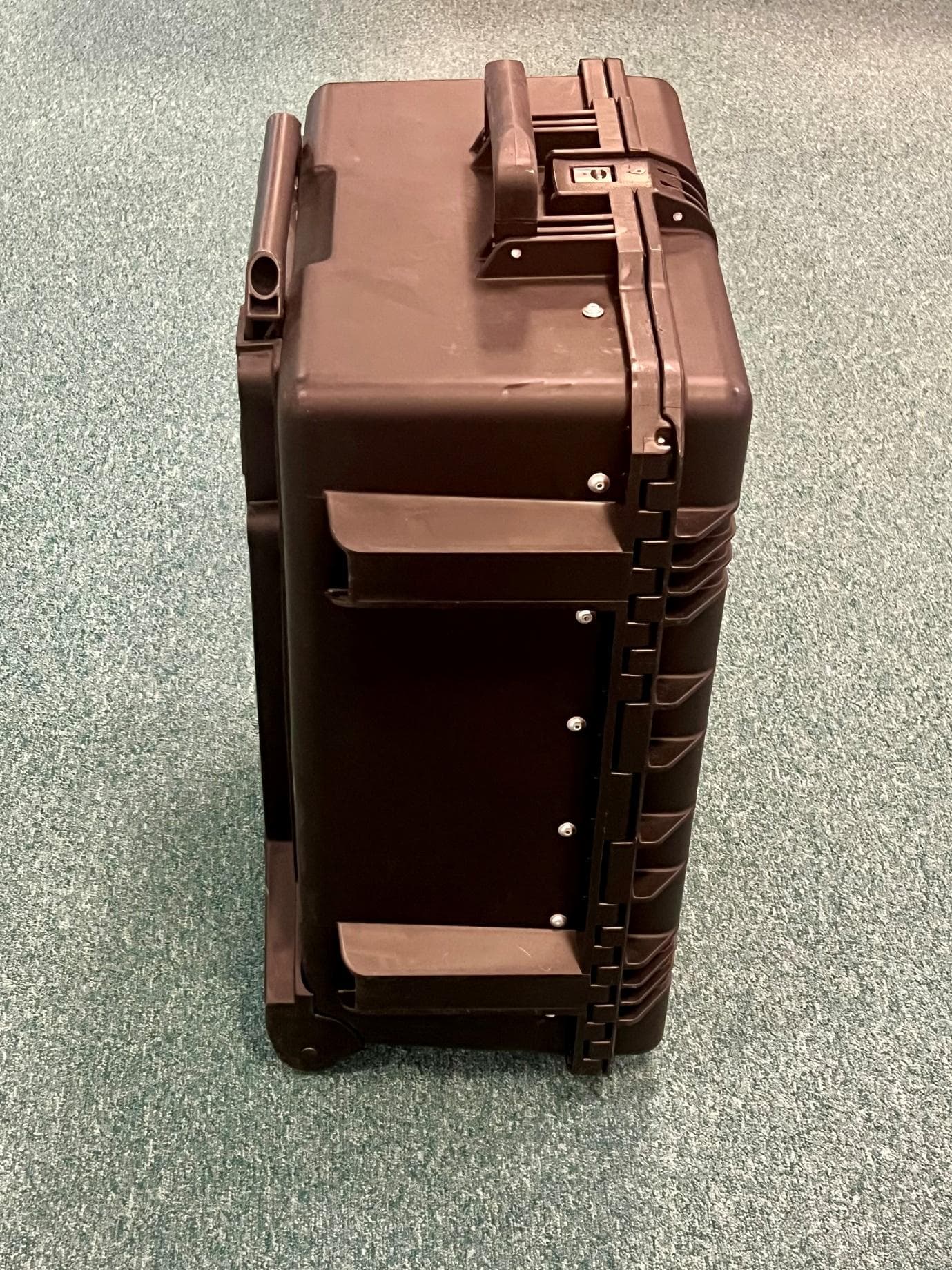
O2J-CBATG
Sep 03, 20264G/5G Small Cell Transportable Base Station used for testing ATG network installations.
Equipment Class
TNB - Licensed Non-Broadcast Station Transmitter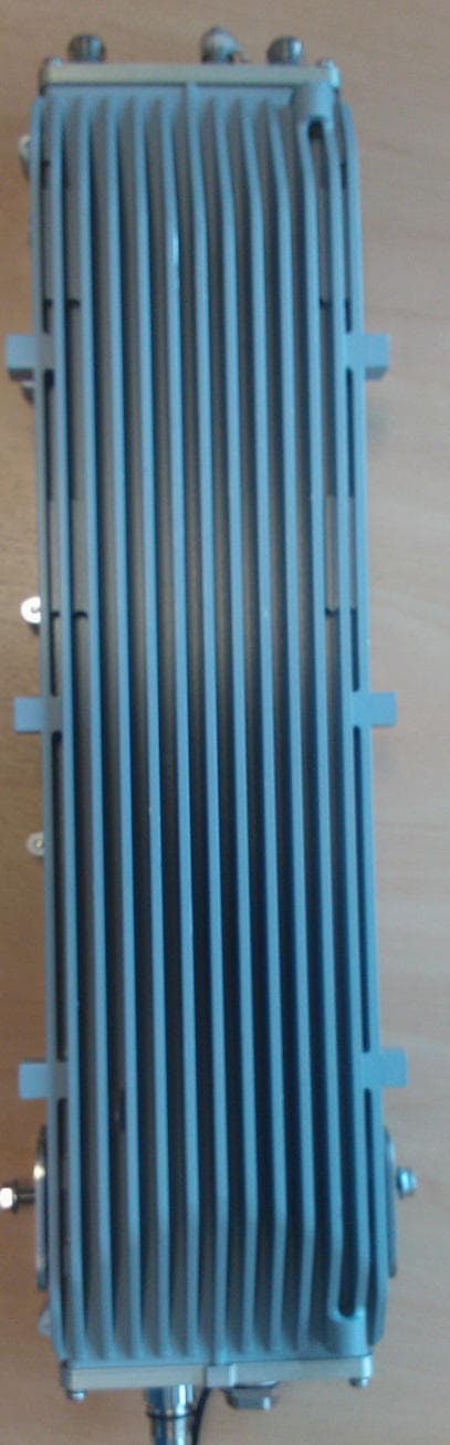
O2J-375AS
Sep 16, 2013Airsynergy Compact Outdoor Pico Base Station
Equipment Class
TNB - Licensed Non-Broadcast Station Transmitter
O2J-235AS
Sep 29, 2011Airsynergy WiMAX Basestation
Equipment Class
TNB - Licensed Non-Broadcast Station Transmitter
O2J-365AS
Sep 13, 2011Airsynergy WiMAX Basestation
Equipment Class
TNB - Licensed Non-Broadcast Station Transmitter
O2J-070T
May 05, 2010700 MHz SCRT
Equipment Class
TNB - Licensed Non-Broadcast Station Transmitter