O2SNURIT8000SSGPCSPayment Terminal
Verifone Inc.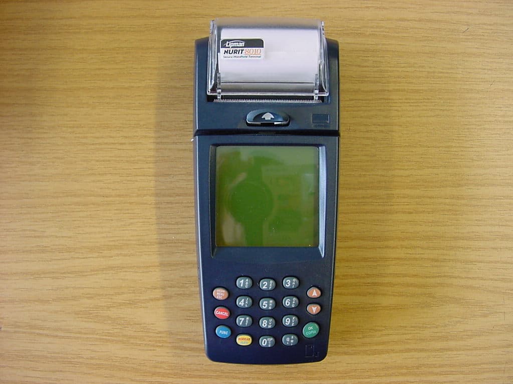
Click to zoom
Application Details
- Equipment Class
- PCB - PCS Licensed Transmitter
- Date of Grant
- May 26, 2004
- Application Purpose
- Original Equipment
- Date of Application
- May 26, 2004
- Equipment Note
- PCSPayment Terminal
- Frequency Range
- 824.20000000 - 848.80000000
- Company
- Verifone Inc.
- Country
- United States
Documents & Files
Document Text
Text extracted from the exhibit documents filed with the FCC. Open a document above to read the original.
Users Manual
NURIT 8000 Wireless Palmtop Solution Installation Manual Copyright Notice Copyright© Lipman Electronic Engineering Ltd. All rights reserved. The content of this publication is for informational purposes only and is subject to change without notice. It does not represent a commitment on the part of Lipman Electronic Engineering Ltd. No part of this publication may be reproduced, transmitted, transcribed, stored in a retrieval system, or translated to any language in any form by any means without the prior written permission of Lipman. Trademark Information NURIT® is a registered trademark of Lipman Electronic Engineering Ltd. All other product and brand names contained in this manual are trademarks of their respective owners. Catalog Number DOC00222 ORIG. Print Date May 2004 Installation Manual iii Foreword Thank you for purchasing the NURIT 8000 Wireless Palmtop Solution. You now own one of the most advanced electronic point- of-sale (POS) terminals manufactured today. This manual provides basic installation instructions. To fully utilize the features of your NURIT 8000, and for general safety purposes, it is recommended that you familiarize yourself with this manual, the terminal and any peripheral equipment or accessories. Figure 1 NURIT 8000 - General View iv Installation Manual Note All graphic images in this manual are for illustrative purposes only. Different models of this terminal may exist and may vary in appearance according to country of use or particular customer requirements. The basic installation procedure is the same for most units. The operation of the terminal is application-dependent. It is recommended that you store this manual in a safe place for future reference. Document Conventions Warning - Failure to follow specific procedures and practices may result in personal injury Caution - Failure to follow specific procedures and practices may result in damage to the NURIT device or other equipment Note - Helpful hints and other important information about the use of the NURIT device Installation Manual v Ta b l e o f C o n t e n t s Copyright Notice ........................................ ii Trademark Information ................................. ii Catalog Number ......................................... ii Print Date................................................. ii Foreword............................................. iii Document Conventions ................................ iv Product Regulatory Information ....................... 1 FCC Compliance Statement............................ 1 FCC Part 15 Requirements ............................. 1 FCC Part 68 Requirements ............................. 2 FCC Part 24 Requirements ............................. 4 In Canada: ................................................ 4 EU Directives Compliance Statement ................ 4 General Safety Instructions.......................... 5 Radio Frequency Energy Emission .................... 9 Safety Precautions for Medical Devices.............10 Pacemakers .............................................10 Other Medical Devices.................................10 Safety Precautions for Other Electronic Devices ..11 Specifications ....................................... 12 Initial Setup ......................................... 13 Unpacking the Box .....................................13 Contents Checklist .....................................14 Selecting a Point-Of-Sale Location ..................17 Optional Accessories ............................... 19 General Features ................................... 23 vi Installation Manual Installing the Battery Pack ........................ 26 Battery Pack Maintenance ............................28 Connecting the NURIT 8000 to an AC Power Outlet . 30 Installing the External Modem.................... 32 Connecting the Car Adapter........................ 33 Loading Paper in the Printer ...................... 35 Installing the Keypad Privacy Shield ............. 37 Installing a SIM or SAM Card......................... 39 Installing the SIM/SAM Cardholder Compartment Cover .. 43 Installing a SIM Card in the TEL SIM Slot ............45 Connecting Peripheral Devices....................... 47 Connecting a Cellular Headset ................... 49 General Care and Maintenance ..................... 50 Cleaning the NURIT 8000..............................50 Cleaning the Printer ...................................51 Maintenance Recommendations .....................52 Technical Assistance ...................................52 Shipping the NURIT 8000 ..............................53 Troubleshooting ..................................... 54 Appendix A Using the Magnetic Card Reader....... 60 Appendix B Using the Smart Card Reader........... 61 Installation Notes................................... 63 Installation Manual vii List of Figures Figure 1 NURIT 8000 - General View iii Figure 2 Secure Device Label 13 Figure 3 NURIT 8000 – Box Contents 16 Figure 4 NURIT 8000 - Optional Accessories 19 Figure 5 NURIT 8000 - Top View 25 Figure 6 NURIT 8000 - Bottom View 25 Figure 7 Battery Pack Installation 26 Figure 8 Battery Pack Removal 27 Figure 9 AC Power Connection 30 Figure 10 External Modem Installation 32 Figure 11 Car Adapter Connection 33 Figure 12 Loading Paper in the Printer 36 Figure 13 Keypad Privacy Shield Installation 37 Figure 14 SIM/SAM Cardholder Locking-Clasp 41 Figure 15 SIM/SAM Card Installation 42 Figure 16 SIM/SAM Cardholder Compartment Cover Installation 44 Figure 17 Void Label Installation 44 Figure 18 SIM Cardholder Ejection 45 Figure 19 SIM Card Installation 46 Figure 20 SIM Cardholder Insertion 46 Figure 21 Barcode Reader Connection 48 Figure 22 Cellular Headset Connection 49 Figure 23 Magnetic Card Reader 60 Figure 24 Smart Card Reader 61 Installation Manual 1 Product Regulatory Information Note The following product regulatory information and compliance statements apply to all models of the NURIT 8000x, where x represents a suffix, such …
Text truncated - open the document above for the full version.
External Photos
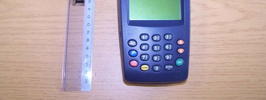
CETECOM ICT Services GmbH Test report no..: 4-1209-01-03/04 Date: 2004.02.24 Page 95 (109) Photographs of EUT Photo No.: 05 CETECOM ICT Services GmbH Test report no..: 4-1209-01-03/04 Date: 2004.02.24 Page 96 (109) Photo No.: 06
ID Label/Location Info
Lipman USA, Incorporated FCC ID: O2SNURIT8000SSG IC: 4804A - N8000SSG INPUT VOLTAGE: 8.4/1A MAX. USE RECOMMENDED LIPMAN CHARGER ONLY Assembled in Israel
Internal Photos
CETECOM ICT Services GmbH Test report no..: 4-1209-01-03/04 Date: 2004.02.24 Page 98 (109) CETECOM ICT Services GmbH Test report no..: 4-1209-01-03/04 Date: 2004.02.24 Page 99 (109) CETECOM ICT Services GmbH Test report no..: 4-1209-01-03/04 Date: 2004.02.24 Page 100 (109) CETECOM ICT Services GmbH Test report no..: 4-1209-01-03/04 Date: 2004.02.24 Page 101 (109) CETECOM ICT Services GmbH Test report no..: 4-1209-01-03/04 Date: 2004.02.24 Page 102 (109) CETECOM ICT Services GmbH Test report no..: 4-1209-01-03/04 Date: 2004.02.24 Page 103 (109) CETECOM ICT Services GmbH Test report no..: 4-1209-01-03/04 Date: 2004.02.24 Page 104 (109) CETECOM ICT Services GmbH Test report no..: 4-1209-01-03/04 Date: 2004.02.24 Page 105 (109) CETECOM ICT Services GmbH Test report no..: 4-1209-01-03/04 Date: 2004.02.24 Page 106 (109) CETECOM ICT Services GmbH Test report no..: 4-1209-01-03/04 Date: 2004.02.24 Page 107 (109) CETECOM ICT Services GmbH Test report no..: 4-1209-01-03/04 Date: 2004.02.24 Page 108 (109) CETECOM ICT Services GmbH Test report no..: 4-1209-01-03/04 Date: 2004.02.24 Page 109 (109)
RF Exposure Info
MPE Calculations FCC Part 1.1310, Table 1 limits the power density for uncontrolled exposure to 1 mW/cm 2 for systems operating in FCC Part 22H and 24E. The distance d (cm) from the antenna at which the power density P d (mW/cm 2 ) is below this limit is calculated from the maximum EIRP, P t (mW) using the equation: P d = P t / √ (4Πd 2 ) Frequency (MHz) Maximum Output Power (dBm) EIRP (mW) P d at 20 cm (mW/cm 2 ) 824 - 849 26.45 442 0.0879 1850 - 1910 31.7 1479 0.0294 The warning information is included in the user manual
Test Report
CETECOM ICT Services GmbH Radio Satellite Communication Untertürkheimer Straße 6-10 . D-66117 Saarbrücken Telefon: +49 (0)681 598-0 Telefax: -9075 Test report No.: 4-1209-01-03/04 This test report consists of 109 pages Page 1 (109) Recognized by the Federal Communications Commission Anechoic chamber registration no.: 90462 (FCC) Anechoic chamber registration no.: 3463 (IC) TCB ID: DE 0001 Accredited by the German Accreditation Council DAR–Registration Number TTI–P–G 081/94-D0 Independent ETSI compliance test house ETSI Accredited Bluetooth™ Test Facility (BQTF) Test report no.: 4_1209-01-03/03 FCC Part 24/22/15 Nurit 8010US-Mxx FCC ID: O2SNURIT8000SSG CETECOM ICT Services GmbH Test report no..: 4-1209-01-03/04 Date: 2004.02.24 Page 2 (109) Table of Contents 1 General information 1.1 Notes 1.2 Testing laboratory 1.3 Details of applicant 1.4 Application details 1.5 Test item 1.6 Test standards 2 Technical test 2.1 Summary of test results 2.2 Test report 1 General information 1.1 Notes The test results of this test report relate exclusively to the test item specified in 1.5. The CETECOM ICT Services GmbH does not assume responsibility for any conclusions and generalizations drawn from the test results with regard to other specimens or samples of the type of the equipment represented by the test item. The test report may only be reproduced or published in full. Reproduction or publication of extracts from the report requires the prior written approval of the CETECOM ICT Services GmbH. 1.2 Testing laboratory CETECOM ICT Services GmbH Untertürkheimer Straße 6 - 10 66117 Saarbrücken Germany Telefone : + 49 681 598 - 9100 Telefax : + 49 681 598 - 9075 E-mail : [email protected] Internet : www.cetecom-ict.de Accredited testing laboratory The test laboratory (area of testing) is accredited according to DIN EN ISO/IEC 17025. DAR registration number: TTI-P-G-081/94-D0 Listed by : Federal Communications Commission (FCC) Identification/Registration No : 90462 Accredited Bluetooth TM Test Facility (BQTF) BLUETOOTH TM is a trademark owned by Bluetooth SIG, Inc. and licensed to CETECOM CETECOM ICT Services GmbH Test report no..: 4-1209-01-03/04 Date: 2004.02.24 Page 3 (109) 1.3 Details of applicant Name : Lipman Electronics Engineering LTD Street : 11 Haamal Street City : 48092 Park Afek Rosh Haayin Country : Israel Telephon : +972-3-9029730 Telefax : +972-3-9029722 Contact : Mr. Arie Geller Telephone : +972-3-9029730 e-mail : [email protected] 1.4 Application details Date of test : 2004-02-18-20 1.5 Test item Type of equipment : Tripple Band 850/1800/1900 MHz PoS Terminal Type designation : Manufacturer : Applicant Street : City : Country : Serial numbers : IMEI :004999.00.273656.01, Ser Nr. 273056 Additional information: : Frequency : 1850.2 – 1909.8 MHz and 824.2 – 848.8 MHz Type of modulation : 300KGXW / 300KG7W Number of channels : 300 (PCS1900) and 125 (PCS850) Antenna : Integrated antenna Power supply (AC) : 100 - 240V (50/60Hz) Output power GSM 850 : cond.: 32.8 dBm Peak , ERP: 24.3 dBm (Burst); EIRP: 26.45 dBm (Burst) Output power GSM 1900 : cond : 29.3 dBm Peak , ERP: 29.55 dBm (Burst); EIRP: 31.7 dBm (Burst) Type of equipment : Temperature range : -30°C - +60°C FCC – ID : O2SNURIT8000SSG IC : Hardware : S30880-S8365-A100(B1) Software : 026 1.6 Test standards: FCC Part 24, 22 FCC Part 15 CETECOM ICT Services GmbH Test report no..: 4-1209-01-03/04 Date: 2004.02.24 Page 4 (109) 2 Technical test For Part 24/22 we use the substitution method ( TIA/EIA 603). All measurements in this report are done in GSM mode. Device is able to transmit data in GPRS mode also. But because the current measurements are performed in PEAK mode no other results from GPRS mode are possible. The only different is the modulation average power, which is 3 dB higher (by using 2 timeslots in the Up-link (GPRS mode 10)). Remarks: No deviations from the technical specification(s) were ascertained in the course of the tests performed. FINAL VERDICT: PASS Technical responsibility for area of testing : 2004-02-24 RSC 8431 Gillmann D. Date Section Name Signature Technical responsibility for area of testing : 2004-02-24 RSC8412 Hausknecht D. Date Section Name Signature CETECOM ICT Services GmbH Test report no..: 4-1209-01-03/04 Date: 2004.02.24 Page 5 (109) 2.2 Test report TEST REPORT Test report no. : 4-1209-01-02/04 CETECOM ICT Services GmbH Test report no..: 4-1209-01-03/04 Date: 2004.02.24 Page 6 (109) TEST REPORT REFERENCE LIST OF MEASUREMENTS PARAMETER TO BE MEASURED PAGE Part PCS 1900 POWER OUTPUT SUBCLAUSE § 24.232 7 FREQUENCY STABILITY SUBCLAUSE § 24.235 9 AFC FREQ ERROR vs. VOLTAGE 12 AFC FREQ ERROR vs. TEMPERATURE 13 EMISSIONS LIMITS SUBCLAUSE §24.238 12 RECEIVER SPURIOUS RADIATION SUBCLAUSE § 15.109 21 CONDUCTED SPURIOUS EMISSIONS 26 BLOCK EDGE COMPLIANCE FOR BLOCK A AND C 35 OCCUPIED BANDWIDTH SUBCLAUSE §2.1049 37 PART PCS 850 POWER OUTPUT SUBCLAUSE § 22.913 44 FREQUENCY STABILITY SUBCLAUSE § 22.355 46 AFC FREQ ERROR vs. VOLTAGE 49 AFC FREQ ERROR vs. TEMPERATURE 50 EMISSIONS LIMITS SUBCLAUSE §22.917 49 RECEIVER SPURIOUS RADIATION SUBCLAUSE § 15.109 58 CONDUCTED SPURIOUS EMISSIONS 62 BLOCK EDGE REQUIREMENTS 71 OCCUPIED BANDWIDTH SUBCLAUSE §2.1049 73 EMISSION LIMITATIONS FOR CELLULAR SUBCLAUSE §22.917(F) 80 TEST EQUIPMENT AND ANCILLARIES USED FOR TESTS 89 Test site 95 CETECOM ICT Services GmbH Test report no..: 4-1209-01-03/04 Date: 2004.02.24 Page 7 (109) REFERENCE NUMBER(S) OF TEST EQUIPMENT USED (for reference numbers see test equipment listing) 64 POWER OUTPUT SUBCLAUSE § 24.232 Summary: This paragraph contains both average , peak output powers and EIRP measurements for the mobile station. In all cases, the peak output power is within the required mask (this mask is specified in the JTC standards, TIA PN3389 Vol. 1 Chap 7, and is no FCC requirement). Method of Measurements: The mobile was set up for the max. output power with pseudo random data modulation. The power was measured with R&S Signal Analyzer FSIQ 26 (…
Text truncated - open the document above for the full version.
Test Setup Photos
CETECOM ICT Services GmbH Test report no..: 4-1209-01-03/04 Date: 2004.02.24 Page 91 (109) Photo No.: 01 CETECOM ICT Services GmbH Test report no..: 4-1209-01-03/04 Date: 2004.02.24 Page 92 (109) Photo No.: 02 CETECOM ICT Services GmbH Test report no..: 4-1209-01-03/04 Date: 2004.02.24 Page 93 (109) Photo No.: 03 CETECOM ICT Services GmbH Test report no..: 4-1209-01-03/04 Date: 2004.02.24 Page 94 (109) Photo No.: 04
Contact Information
Applicant
Andrey Glemb(Certificate Engineer)
Technical Contact
Lipman Electronics Engineering LTDAvi Galili
[email protected]972 3 9029730
11 Haamal Street · Park Afek Rosh Haayin · Israel
Non-Technical Contact
Lipman Electronics Engineering LTDAvi Galili
[email protected]972 3 9029730
Test Firm
Cetecom ICT Services GmbHRalf Hoehn
Technical Specifications
| # | Rule Parts | Frequency Range | Power Output | Emission | Tolerance |
|---|---|---|---|---|---|
| 2 | 22H | 824.2 MHz - 848.8 MHz | 302.00 mW | 300KGXW | 0.04 ppm |
Other Applications from Verifone Inc.
O2SNURIT8000SSQ
Dec 12, 2005Hand held Payment Terminal
Equipment Class
PCB - PCS Licensed Transmitter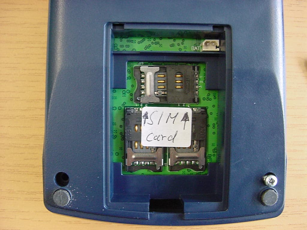
O2SNURIT8320S4
Jul 04, 2005PCS Payment Terminal
Equipment Class
PCB - PCS Licensed Transmitter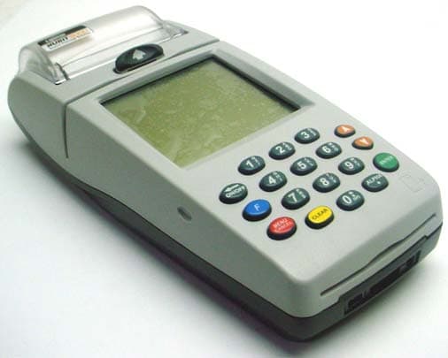
O2SNURIT8000SWD
Apr 04, 2004Hand Held Point of Sale Device
Equipment Class
TNB - Licensed Non-Broadcast Station Transmitter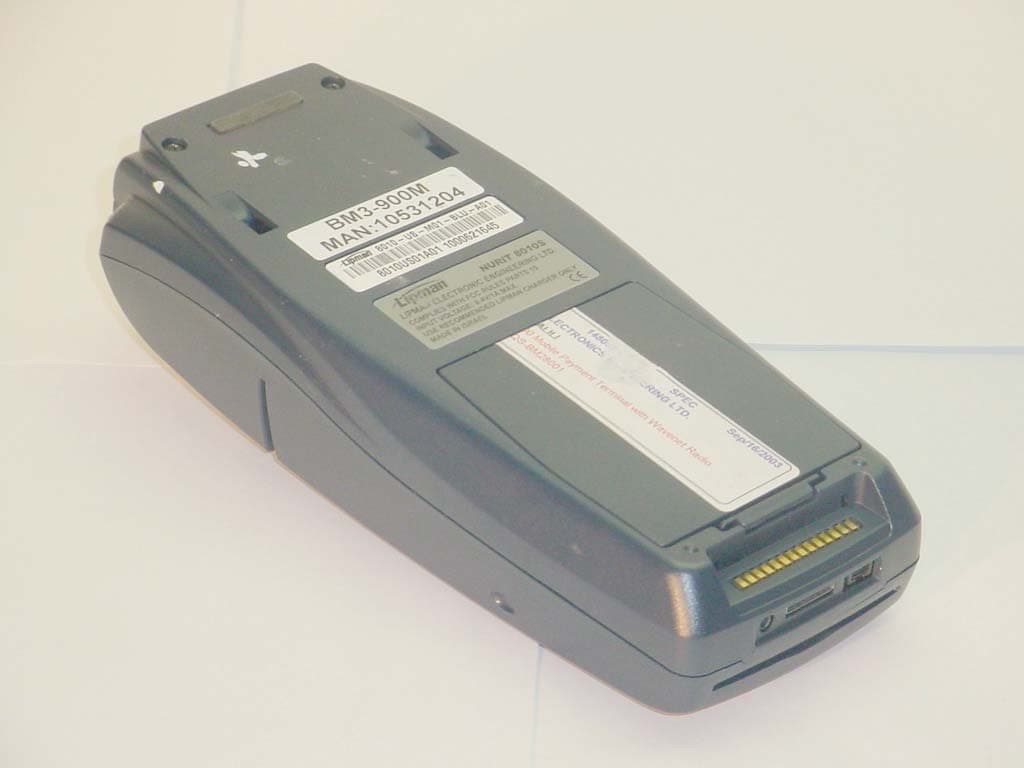
O2SNURIT8000SWM
Feb 12, 2004POINT OF SALE DEVICE
Equipment Class
TNB - Licensed Non-Broadcast Station Transmitter
O2SNURIT8000AI
May 30, 2002NURIT 8000
Equipment Class
TNF - Licensed Non-Broadcast Transmitter Held to Face