O34-CPEM-E1K6567CONTACTLESS PAYMENT EXPANSION MODULE
Ingenico
Click to zoom
Application Details
- Equipment Class
- DXX - Part 15 Low Power Communication Device Transmitter
- Date of Grant
- Aug 25, 2005
- Application Purpose
- Original Equipment
- Date of Application
- Aug 25, 2005
- Equipment Note
- CONTACTLESS PAYMENT EXPANSION MODULE
- Frequency Range
- 13.56000000 - 13.56000000
- Company
- Ingenico
- Country
- Canada
Documents & Files
Document Text
Text extracted from the exhibit documents filed with the FCC. Open a document above to read the original.
Users Manual
Contactless Payment Expansion Module for the e N -Touch 1000 Installation Guide Contactless Payment Expansion Module e N –Touch 1000 Installation Guide Contactless Payment Expansion Module for the e N –Touch 1000 Installation Guide Part Number DIV350403, Revision A Released July 2005 Copyright 2005, Ingenico Corp. All rights reserved. No part of this publication may be copied, distributed, stored in a retrieval system, translated into any human or computer language, transmitted, in any form or by any means, without the prior written consent of Ingenico. Ingenico and Ingenico logo are registered trademarks of Ingenico Corp. All other brand names and trademarks appearing in this guide are the property of their respective holders. Information in this document is subject to change without notice. Noncontractual document. INGENICO owns exclusive rights to this document. All distributions, copies, entire or partial production, by any process, made without the authorization of INGENICO will be considered illicit, and will form an infringement, penalized by the L.335-2 clause and following clauses of the Code of Intellectual Property. INGENICO reserves the right to modify the characteristics and the functions of this device without notice. INGENICO is not responsible for any use of this device which would be inconsistent with this document. Ingenico Inc. 1003 Mansell Road Atlanta, GA 30076 Tel: 770.594.6000 Fax: 770.594.6003 www.ingenico-us.com U.S. Help Desk: TotalCARE Tel: 800.435.3014 Fax: 770.594.6026 Ingenico Canada Ltd. 79 Torbarrie Road, Toronto, Ontario Canada M3L 1G5 Tel: 416.245.6700 Fax: 416.245.6701 www.ingenico-ca.com Canadian Help Desk: TotalCARE. Tel: 888.900.8221 Fax: 905.795.9343 Contactless Payment Expansion Module e N –Touch 1000 Installation Guide 1 Table of Contents 1 Overview .............................................. 1 2 Installation Components ....................... 1 3 Installation Procedure .......................... 2 3.1 Preparing the Terminal for the Installation ................................ 2 3.2 Expansion Module Installation Steps......................................... 3 4 Testing the Installation ......................... 6 5 Product Certification ............................ 7 1 Overview This document describes how to install the Contactless Payment Expansion Module on the e N -Touch 1000 terminal. The Expansion Module is based on RFID technology and enables the terminal to read contact-less smartcards. The e N -Touch 1000 is available in 2 models, Tyco/Loki and Thor that have different plastic feet. See Figure 1. Figure 1: Terminal Foot area for Thor and Tyco/Loki models This installation guide applies to both models. 2 Installation Components The Expansion Module package contains all the components required for upgrading either of the two e N -Touch 1000 models. The kit T yco/LokiThor 2 Contactless Payment Expansion Module e N –Touch 1000 Installation Guide includes the following: Card Reader Unit, Cable, Tyco/Loki Foot, Thor Foot, Wedge, Double sided tape and Plastic bag with one mounting screw and two self-adhesive rubber bumps Only the Expansion Module Foot for your terminal model is required! 3 Installation Procedure ! - Only upgrade terminals that are in working order. - This procedure requires a Philips screw driver. 3.1 Preparing the Terminal for the Installation 1. Disconnect the terminal from power. 2. Place the terminal on a flat surface with the bottom side facing up. 3. Remove the existing Foot from the terminal. Note different procedure for the two models: • Thor model only: Using a screwdriver remove the two mounting screws and detach the Foot. Retain the screws for the Expansion Module installation. • Tyco/Loki model only: Pinch the middle of the Foot to release the locking clip and then remove the Foot. See Figure 2. Figure 2: Removing the existing Tyco/Loki Foot 4. Disconnect any installed cables from the terminal. Contactless Payment Expansion Module e N –Touch 1000 Installation Guide 3 3.2 Expansion Module Installation Steps Step 1: Assemble the cable assembly into the Foot required for your installation as shown in Figure 3. Ensure that the cable is positioned in the cable retention feature of the Foot. Note that the cable is routed differently according to the model you have: for the Tyco/Loki model place the Minidin 9 cable under the RJ cable. Figure 3: Cable/Foot assembly Step 2: Insert the RJ connector from the assembled Cable/Foot into the Reader Unit jack, as shown in Figure 4. Figure 4: Connect RJ cable to the Reader Unit Step 3: Attach the Reader Unit to the Foot by using the two foot mounting tabs and the mounting screw. See Figure 5 Tyco/Loki Thor Reader Unit RJ Minidin 9 RJ Minidin 9 Screw hole Antenna 4 Contactless Payment Expansion Module e N –Touch 1000 Installation Guide Figure 5: Foot/Reader Unit assembly Step 4A-Tyco/Loki model only: Attach the Foot/Reader Unit assembly to the terminal by connecting first the Minidin 9 connector to the terminal jack, than placing the two bottom mounting tabs of the Foot into the terminal recesses and finally by squeezing in the top mounting tab of the Foot into matching locating hole of the terminal. Foot mounting screws are NOT required. See Figure 6. Figure 6: Attach Tyco/Loki Expansion Module to the terminal Step 4B-Thor model only: Same procedure as for Tyco/Loki model except the different position of the Foot mounting tabs, Foot mounting screws and of the Minidin 9 terminal jack. Foot mounting screws need to be applied. Use the screws removed from the terminal Foot. See Figure 7. Mounting screw Contactless Payment Expansion Module e N –Touch 1000 Installation Guide 5 Figure 7: Attach the Thor Expansion Module to the terminal Step 5: Apply the two self-adhesive rubber bumps to the Module Foot as shown in Figure 7. The orientation angle of the Card Reader antenna can be adjusted through 3 discrete positions. The optional Antenna Positioning Wedge included in the kit can be used…
Text truncated - open the document above for the full version.
External Photos
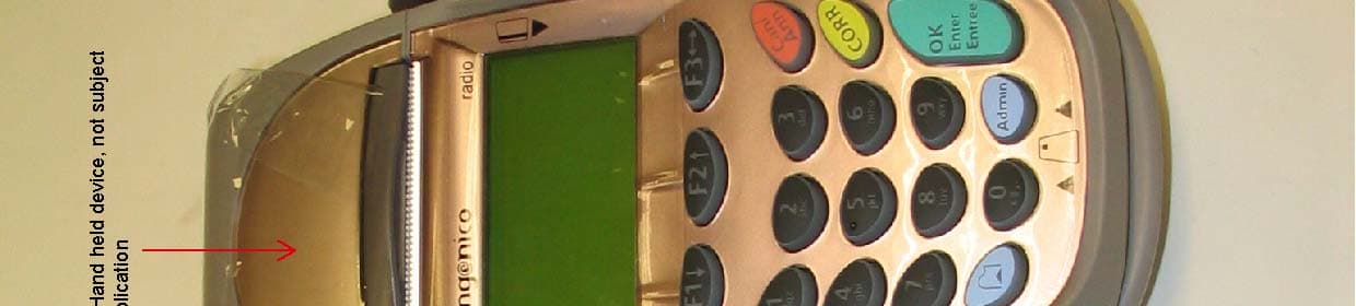
ANNEX 2 – EXTERNAL PHOTOGRAPHS Ingenico Contactless Payment Expansion Module FCC ID: O34-CPEM-E1K6567 IC: 2586B-CP1K6567 A2 - 1 ANNEX 2 – EXTERNAL PHOTOGRAPHS Ingenico Contactless Payment Expansion Module FCC ID: O34-CPEM-E1K6567 IC: 2586B-CP1K6567 A2 - 2 ANNEX 2 – EXTERNAL PHOTOGRAPHS Ingenico Contactless Payment Expansion Module FCC ID: O34-CPEM-E1K6567 IC: 2586B-CP1K6567 A2 - 3 ANNEX 2 – EXTERNAL PHOTOGRAPHS Ingenico Contactless Payment Expansion Module FCC ID: O34-CPEM-E1K6567 IC: 2586B-CP1K6567 A2 - 4
ID Label/Location Info
Size: 2 3/16” X 11/16” ( 55.6mm x 17.5mm) 0.04” (1mm) Corner Rad Label Colors: White Material Stock Ingenico 79 Torbarrie Road Toronto ON M3L 1G5 T (416) 245-6700 F (416) 245-6701 LABEL, CTLS PMT EXP MOD ETI350383 A Label Specifications: Material: Gloss White Polyester Thermal Transfer 3M 7816, Identco TT760, or Equivalent UL/CSA Approved LABEL - Scaled 200% (Identifiers and grey areas for representation only) LABEL - 100% Actual Size (Grey areas for representation only) TITLE DOC NUMBERREV REV DESCRIPTION DRWN ECO DATE A INITIAL RELEASE JL 2005/08/16 FILE NAME USED ON THIS DOCUMENT IS THE PROPRIETARY PROPERTY OF INGENICO. NO USE OR DISSEMINATION IN ANY FORM IS PERMITTED WITHOUT PRIOR WRITTEN AUTHORIZATION FROM INGENICO. ALL RIGHTS RESERVED. Notes: 1. Customer serial number to be defined by customer. 2. Refer to Ingenico label document LI-11005 for all numbering formats. Black Logos, Graphics, Text, Barcodes **Label outline, A,B,C,D,E identifiers and grey areas indicate barcode locations and are for graphic representation only. 2 3/16 1/32 TYP 11/16 1/32 TYP ETI350383-A_LABEL_CTLS PMT EXP MOD.PDF A - Manufacturer Serial Number (Barcode) Code 3 of 9 B - Manufacturer Serial Number (Human Readable) C - Manufacturing Location ( See Specification document for location) eg. Made in / Fabriqu é en Canada Made in Mexico . D - Revision Code Human Readable Information - Ht: 4 pt min. MFR FCC ID: ETI350383 CONTACTLESS PAYMENT EXPANSION MODULE PN: SEN350377 Made in / Fabriqué en Canada IC: SN: A B O34-CPEM-E1K6567 2586B-CP1K6567 C MFR FCC ID: ETI350383 CONTACTLESS PAYMENT EXPANSION MODULE PN: SEN350377 Made in / Fabriqué en Canada IC: SN: A B O34-CPEM-E1K6567 2586B-CP1K6567 MFR FCC ID: ETI350383 CONTACTLESS PAYMENT EXPANSION MODULE PN: SEN350377 Made in / Fabriqué en Canada IC: SN: D DD O34-CPEM-E1K6567 2586B-CP1K6567 Text Arial & Arial Black Font 1.5" 0.5" Font: Ariel All print to be in black and font scaled to fit the label as shown above. To be printed on Blank label P/N ETIxxxx (1.5" x 0.5") Print to be high quality and fully legible Label: White adhesive Polyester, UL/CSA approved ADOD25th Aug 05Origination of document RevInitialsDateComments Part Description: FCC LABEL PRINTING INSTRUCTION RFID Finish:Printing specification onlyDrawn By : DODChecked by :DOD Material: Print on P/N ETIxxxxDate: 25/08/2005SPECIFxxxxxxA 1/1 This device complies with Part 15 of the FCC Rules. Operation is subject to the following two conditions: (1) this device may not cause harmful interference and (2) this device must accept any interference received, including interference that may cause undesired operation. Product Label Location (Rear of the unit) FCC Label Location
Internal Photos
ANNEX 3 – INTERNAL PHOTOGRAPHS Ingenico Contactless Payment Expansion Module FCC ID: O34-CPEM-E1K6567 IC: 2586B-CP1K6567 A2 - 1 ANNEX 3 – INTERNAL PHOTOGRAPHS Ingenico Contactless Payment Expansion Module FCC ID: O34-CPEM-E1K6567 IC: 2586B-CP1K6567 A2 - 2 ANNEX 3 – INTERNAL PHOTOGRAPHS Ingenico Contactless Payment Expansion Module FCC ID: O34-CPEM-E1K6567 IC: 2586B-CP1K6567 A2 - 3 ANNEX 3 – INTERNAL PHOTOGRAPHS Ingenico Contactless Payment Expansion Module FCC ID: O34-CPEM-E1K6567 IC: 2586B-CP1K6567 A2 - 4 ANNEX 3 – INTERNAL PHOTOGRAPHS Ingenico Contactless Payment Expansion Module FCC ID: O34-CPEM-E1K6567 IC: 2586B-CP1K6567 A2 - 5 ANNEX 3 – INTERNAL PHOTOGRAPHS Ingenico Contactless Payment Expansion Module FCC ID: O34-CPEM-E1K6567 IC: 2586B-CP1K6567 A2 - 6 ANNEX 3 – INTERNAL PHOTOGRAPHS Ingenico Contactless Payment Expansion Module FCC ID: O34-CPEM-E1K6567 IC: 2586B-CP1K6567 A2 - 7
Test Report
Contactless Payment Expansion Module FCC ID: O34-CPEM-E1K6567 Applicant: Ingenico 76 Torbarrie Road Toronto, ON Canada, M3L 1G5 In Accordance With Federal Communications Commission (FCC) Part 15, Subpart C, Section 15.225 Unlicensed Low Power Transmitter Operating in the Band 13.110-14.010 MHz UltraTech's File No.: IVI-164F15C225 This Test report is Issued under the Authority of Tri M. Luu, Professional Engineer, Vice President of Engineering UltraTech Group of Labs Date: August 11, 2005 Report Prepared by: Anca Dobre Issued Date: August 11, 2005 Tested by: Hung Trinh, RFI Technician Test Dates: July 21-29 & August 5, 2005 The results in this Test Report apply only to the sample(s) tested, and the sample tested is randomly selected. This report must not be used by the client to claim product endorsement by NVLAP or any agency of the US Government. UltraTech 3000 Bristol Circle, Oakville, Ontario, Canada, L6H 6G4 Tel.: (905) 829-1570 Fax.: (905) 829-8050 Website: www.ultratech-labs.com , Email: [email protected], Email: [email protected] 2 31040/SIT C-1376 46390-2049 200093-0 SL2-IN-E-1119R 00-034 FCC Part 15, Subpart C, Section 15.225, Low Power Communication Device Transmitter Contents i Contactless Payment Expansion Module FCC ID: O34-CPEM-E1K6567 ULTRATECH GROUP OF LABS File #: IVI-164F15C225 3000 Bristol Circle, Oakville, Ontario, Canada L6H 6G4 August 11, 2005 Tel. #: 905-829-1570, Fax. #: 905-829-8050, Email: [email protected] , Website: http://www.ultratech-labs.com All test results contained in this engineering test report are traceable to National Institute of Standards and Technology (NIST) TABLE OF CONTENTS EXHIBIT 1: SUBMITTAL CHECK LIST ..........................................................................................................................................1 EXHIBIT 2: INTRODUCTION ............................................................................................................................................................2 2.1. SCOPE ............................................................................................................................................................................................2 2.2. RELATED SUBMITTAL(S)/GRANT(S) .......................................................................................................................................2 2.3. NORMATIVE REFERENCES .......................................................................................................................................................2 EXHIBIT 3: PERFORMANCE ASSESSMENT .................................................................................................................................3 3.1. CLIENT INFORMATION ..............................................................................................................................................................3 3.2. EQUIPMENT UNDER TEST (EUT) INFORMATION..................................................................................................................3 3.3. EUT’S TECHNICAL SPECIFICATIONS ......................................................................................................................................4 3.4. LIST OF EUT’S PORTS .................................................................................................................................................................4 3.5. ANCILLARY EQUIPMENT ..........................................................................................................................................................4 3.6. GENERAL TEST SETUP ...............................................................................................................................................................5 EXHIBIT 4: EUT OPERATING CONDITIONS AND CONFIGURATIONS DURING TESTS...................................................6 4.1. CLIMATE TEST CONDITIONS ....................................................................................................................................................6 4.2. OPERATIONAL TEST CONDITIONS & ARRANGEMENT FOR TESTS ..................................................................................6 EXHIBIT 5: SUMMARY OF TEST RESULTS..................................................................................................................................7 5.1. LOCATION OF TESTS ..................................................................................................................................................................7 5.2. APPLICABILITY & SUMMARY OF EMC EMISSION TEST RESULTS....................................................................................7 5.3. MODIFICATIONS INCORPORATED IN THE EUT FOR COMPLIANCE PURPOSES .............................................................7 EXHIBIT 6: MEASUREMENTS, EXAMINATIONS & TEST DATA FOR EMC EMISSIONS ..................................................8 6.1. TEST PROCEDURES.....................................................................................................................................................................8 6.2. MEASUREMENT UNCERTAINTIES...........................................................................................................................................8 6.3. MEASUREMENT EQUIPMENT USED ........................................................................................................................................8 6.4. ESSENTIAL/PRIMARY FUNCTIONS AS DECLARED BY THE MANUACTURER ................................................................8 6.5. COMPLIANCE WITH FCC PART 15 – GENERAL TECHNICAL REQUIREMENTS................................................................8 6.6. AC POWERLINE CONDUCTED EMISSIONS [§§ 15. 107(A) & 15.207].....................................................................................9 6.7. 26 dB BANDWIDTH [§ 2.1049]........................................…
Text truncated - open the document above for the full version.
Test Setup Photos
ANNEX 1 - TEST SETUP PHOTOGRAPHS Ingenico Contactless Payment Expansion Module FCC ID: O34-CPEM-E1K6567 A1 - 1 ANNEX 1 - TEST SETUP PHOTOGRAPHS Ingenico Contactless Payment Expansion Module FCC ID: O34-CPEM-E1K6567 A1 - 2 ANNEX 1 - TEST SETUP PHOTOGRAPHS Ingenico Contactless Payment Expansion Module FCC ID: O34-CPEM-E1K6567 A1 - 3
Contact Information
Applicant
Kandeepan K.
(416) 245-6700Fax: (416) 245-6701
Test Firm
UltraTech Engineering Labs Inc.Tri Luu
Technical Specifications
| # | Rule Parts | Frequency Range | Power Output |
|---|---|---|---|
| 1 | 15C | 13.56 MHz - 13.56 MHz | - |
Other Applications from Ingenico
O34-I7770RBBT2
Jun 16, 2005Point of Sale, Base Station
Equipment Class
DSS - Part 15 Spread Spectrum Transmitter
O34-I7770BT2
Jun 16, 2005Point of Sale, Hand held Terminal
Equipment Class
DSS - Part 15 Spread Spectrum Transmitter
O34-GPRS
Nov 01, 2004ELITE 790 GPRS POINT OF SALE TERMINAL
Equipment Class
PCT - PCS Licensed Transmitter worn on body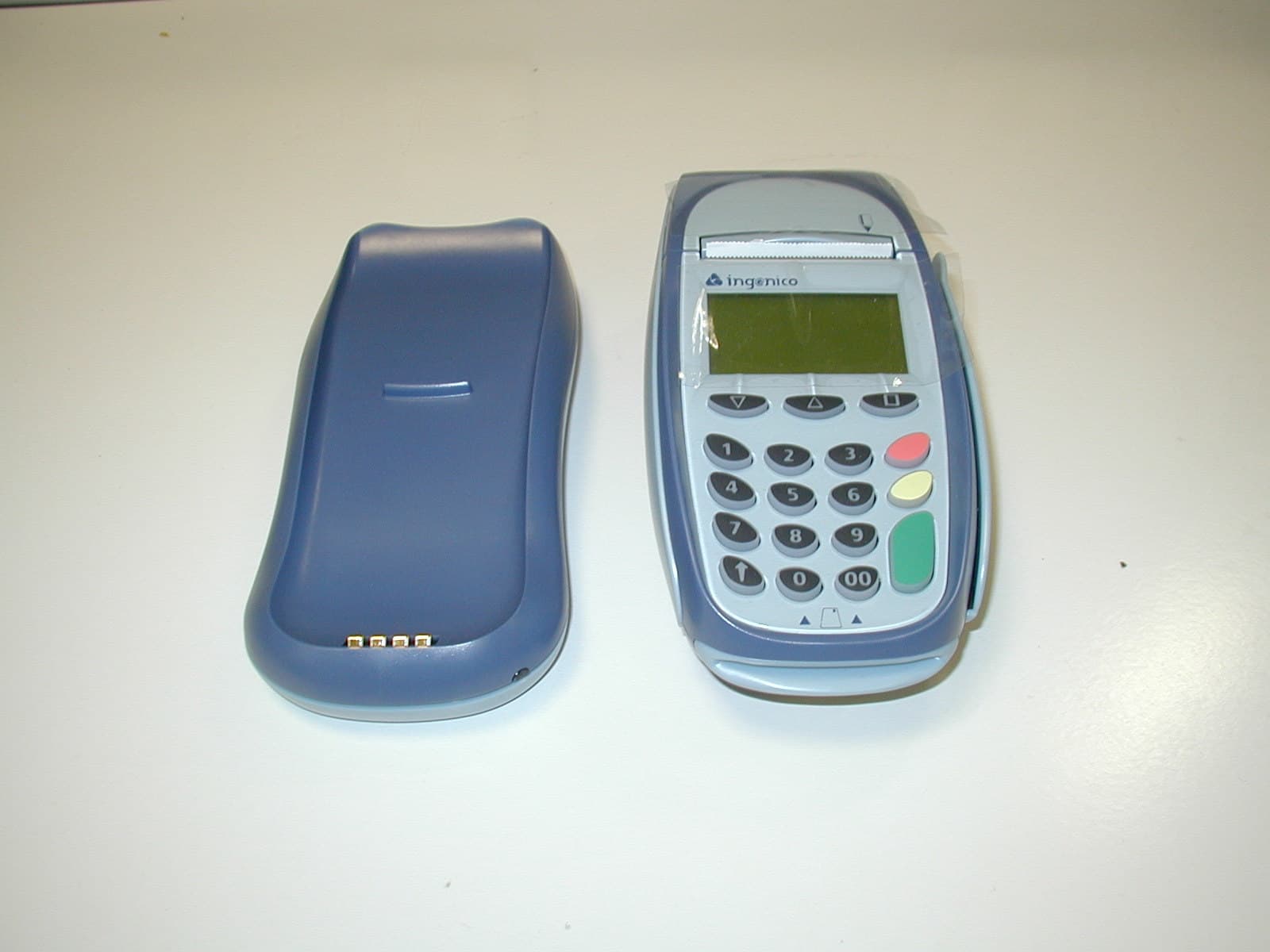
O34-I7770BASE
May 25, 2004Point of sale, base station
Equipment Class
DSS - Part 15 Spread Spectrum Transmitter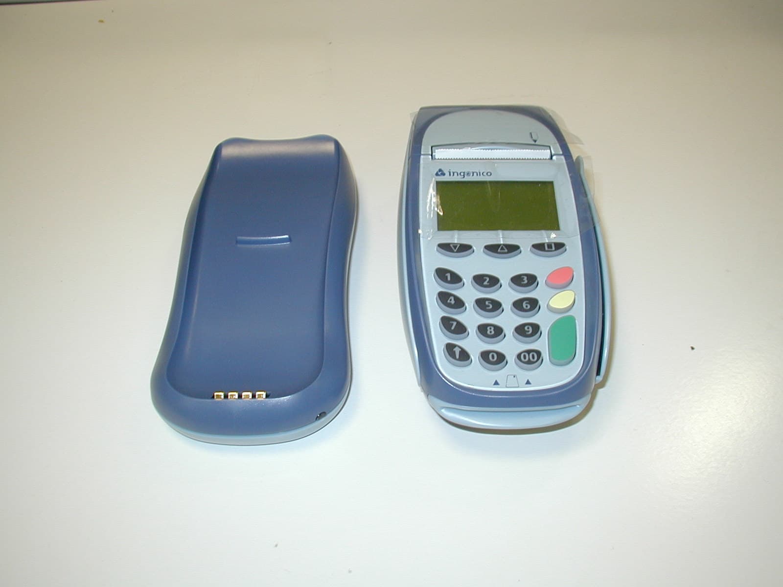
O34-I7770
May 05, 2004Point of sale hand held terminal
Equipment Class
DSS - Part 15 Spread Spectrum Transmitter