O34-I7770RBBT2Point of Sale, Base Station
Ingenico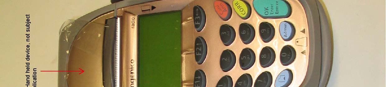
Click to zoom
Application Details
- Equipment Class
- DSS - Part 15 Spread Spectrum Transmitter
- Date of Grant
- Jun 16, 2005
- Application Purpose
- Original Equipment
- Date of Application
- Jun 16, 2005
- Equipment Note
- Point of Sale, Base Station
- Frequency Range
- 2402.00000000 - 2480.00000000
- Company
- Ingenico
- Country
- Canada
Documents & Files
Document Text
Text extracted from the exhibit documents filed with the FCC. Open a document above to read the original.
Users Manual
• DIAL LINE and PHONE CONNECTIONS The ports marked EXT LINE and are identical. Use either one of these ports to connect the i7770 modem to the telephone line: plug the one end of a telephone cable into the port, and connect the other end of the cable to a wall telephone jack. Use the remaining port to c onnect the phone, fax or other device that will share the same phone line with the i7770. Plug one end of a telephone cable into the i7770 port ( EXT LINE or ), and plug the other end of the cable in the device. • PERIPHERAL/HOST CONNECTION Unplug the i7770 radio base. Co nnect the serial cable to the base port marked COM2 or COM1/3 . Plug the other end of the serial cable to the device (PC, check reader etc.). For detailed instructions, ask the equipment supplier. • POWER CONNECTION Plug the power adapter radial jack into the i7770 base port marked . The green light on the front right hand side of the base indicates the power is on. Attach the cable securing plate and fix it with a screw. 3.5. Changing the printer paper: When the coloured stripe on the paper appears, replace the paper: Remove the i7770 from the base and wait till it turns off, do not touch the printer parts. Be aware of the sharp paper cutter. 1. Push the button on the paper compartment cover toward the back and lift the cover. 2. Remove the empty paper roll and insert the new roll ensuring the paper is protruding from UNDERNEATH the roll. 3. To close the cover, press it until it snaps. Press the “Paper feed” key to verify that paper feeds properly. 4. Normal Operation : To extend the battery life, the i7770 hand held terminal goes into a stand-by mode when it is not on its base. To quickly power on the hand held terminal: • Press the green <ENTER> key, or • Place the hand held briefly on the base. The symbol in the upper left hand corner of the screen indicates that the hand held terminal is assigned to its base and it is in the range (the s earch phase typically lasts less than 10s). The message - RANGE - appears when the Bluetooth radio link is not available: • The hand held terminal is out of range. • The terminal is scanning for the base while initiating communication. • The hand held terminal is configured with the wrong base serial number. Go to the SYSTEM MENU, select the “RADIO CONFIG” and run “MOD RADIO PARA”. • The radio base is not powered up. The message - BUSY - appears when the hand held terminal tries to connect to a base while it is communicating with another terminal. Wait until the base becomes available. The message FULL appears when the maximum number of terminals configured for a base is exceeded. Remove the extra terminals from the network, power off the radio base and turn it back on to reinitialize. 5. Cleaning procedure: The i7770 must be off for all cleaning operations. Do not clean the i7770 with water but with a dry or only slightly damp cloth. Do not use solvent, detergent or abrasive products. If the terminal has battery recharging or communication problems, clean the golden contact under the terminal with a damp cloth. Do not scratch or scrape the surface of the contacts. 6. Technical specifications: The i7770 uses a low power (20dBm, ≤ 100mW) Bluetooth technology with frequency hopping in the 2.45Ghz ISM band. The i7770 range is around 100 m (open field). 6.1. Power supply: The power adapter is mainly used for charging the internal battery. • INPUT ................ AC 120V 60Hz • OUTPUT . DC 18V 0.9A 16.2VA 6.2. Thermal Paper Specification: • Single ply thermal sensitive – POS or facsimile grade. • Basis Weight: (lb/rm 17 in s. X 22 ins. - 500) -- 14.5 ± 5% (GSM) -- 55 ± 5% • Caliper .......................... 2.4 ± 0.2 Mils or 60 ± 5 Microns • Brightness ......................................................... Min. 85% • Smoothness (Bekk Minimum) ..................................300 s • Roll Width ................. 2.28 ± 0.040 in (58 mm ± 1.0 mm) • Roll Diameter ........................ 1.97 in (50 mm) maximum • Roll Core ID ........................... 0.500 in (13 mm) nominal • Roll Core OD .......................... 0.625 in ( 16 mm) nominal Recommended brands: KANZAN .................... KF50 JUJO ....................AF50KS-E KOEHLER..........KT55HS01 MITSUBIS HI.............. P6402 Thermal paper should NOT be exposed to vinyl, plastics, adhesives, shrink-wraps, wet-toner copies or certain carbon papers, office light UV light, high humidity and temperature (above 65%, 25 ° C or 77 ° F) for long periods of time. 7. If you experience problems : Call one of the customer service centers listed below: In Canada: In the USA: TotalCARE Ingenico Inc. 6520 Gottardo Court TotalCARE Mississauga, Ontario 1003 Mansell Road L5T 2A2 Atlanta, GA 30076 1-888-900-8221 (905-795-8221) 1-800-435-3014 (770-594-6000) US Federal Communications Commission (FCC) Warnings: This equipment has been tested and found to comply with the limits for a Class B digital device, pursuant to Part 15 of the FCC Rules. These limits are designed to provide reas onable protection against harmful interference when this equipment is operated in a commercial environment. This equipment generates, uses, and can radiate radio frequency energy and, if not installed and used in accordance with th e installation guide, may cause harmful interference to radio communications. Operation of this equipment in a residential area is likely to cause harmful interference in which case the user will be required to correct the interference at his own expense. Warning: Changes or modifications not expressly approved by Ingenico could void the user’s authority to operate the equipment. Canadian Department of Communications (DOC) Warnings: This digital apparatus does not exceed the Class B limits for radio noise emissions from the digital apparatus as set out in the radio interference regulations of the Canadian Department of Communications. RF Exposure Warning : To comply with RF exposure requirements the base unit must be installed and…
Text truncated - open the document above for the full version.
Users Manual
• DIAL LINE and PHONE CONNECTIONS The ports marked EXT LINE and are identical. Use either one of these ports to connect the i7770 modem to the telephone line: plug the one end of a telephone cable into the port, and connect the other end of the cable to a wall telephone jack. Use the remaining port to c onnect the phone, fax or other device that will share the same phone line with the i7770. Plug one end of a telephone cable into the i7770 port ( EXT LINE or ), and plug the other end of the cable in the device. • PERIPHERAL/HOST CONNECTION Unplug the i7770 radio base. Co nnect the serial cable to the base port marked COM2 or COM1/3 . Plug the other end of the serial cable to the device (PC, check reader etc.). For detailed instructions, ask the equipment supplier. • POWER CONNECTION Plug the power adapter radial jack into the i7770 base port marked . The green light on the front right hand side of the base indicates the power is on. Attach the cable securing plate and fix it with a screw. 3.5. Changing the printer paper: When the coloured stripe on the paper appears, replace the paper: Remove the i7770 from the base and wait till it turns off, do not touch the printer parts. Be aware of the sharp paper cutter. 1. Push the button on the paper compartment cover toward the back and lift the cover. 2. Remove the empty paper roll and insert the new roll ensuring the paper is protruding from UNDERNEATH the roll. 3. To close the cover, press it until it snaps. Press the “Paper feed” key to verify that paper feeds properly. 4. Normal Operation : To extend the battery life, the i7770 hand held terminal goes into a stand-by mode when it is not on its base. To quickly power on the hand held terminal: • Press the green <ENTER> key, or • Place the hand held briefly on the base. The symbol in the upper left hand corner of the screen indicates that the hand held terminal is assigned to its base and it is in the range (the s earch phase typically lasts less than 10s). The message - RANGE - appears when the Bluetooth radio link is not available: • The hand held terminal is out of range. • The terminal is scanning for the base while initiating communication. • The hand held terminal is configured with the wrong base serial number. Go to the SYSTEM MENU, select the “RADIO CONFIG” and run “MOD RADIO PARA”. • The radio base is not powered up. The message - BUSY - appears when the hand held terminal tries to connect to a base while it is communicating with another terminal. Wait until the base becomes available. The message FULL appears when the maximum number of terminals configured for a base is exceeded. Remove the extra terminals from the network, power off the radio base and turn it back on to reinitialize. 5. Cleaning procedure: The i7770 must be off for all cleaning operations. Do not clean the i7770 with water but with a dry or only slightly damp cloth. Do not use solvent, detergent or abrasive products. If the terminal has battery recharging or communication problems, clean the golden contact under the terminal with a damp cloth. Do not scratch or scrape the surface of the contacts. 6. Technical specifications: The i7770 uses a low power (20dBm, ≤ 100mW) Bluetooth technology with frequency hopping in the 2.45Ghz ISM band. The i7770 range is around 100 m (open field). 6.1. Power supply: The power adapter is mainly used for charging the internal battery. • INPUT ................ AC 120V 60Hz • OUTPUT . DC 18V 0.9A 16.2VA 6.2. Thermal Paper Specification: • Single ply thermal sensitive – POS or facsimile grade. • Basis Weight: (lb/rm 17 in s. X 22 ins. - 500) -- 14.5 ± 5% (GSM) -- 55 ± 5% • Caliper .......................... 2.4 ± 0.2 Mils or 60 ± 5 Microns • Brightness ......................................................... Min. 85% • Smoothness (Bekk Minimum) ..................................300 s • Roll Width ................. 2.28 ± 0.040 in (58 mm ± 1.0 mm) • Roll Diameter ........................ 1.97 in (50 mm) maximum • Roll Core ID ........................... 0.500 in (13 mm) nominal • Roll Core OD .......................... 0.625 in ( 16 mm) nominal Recommended brands: KANZAN .................... KF50 JUJO ....................AF50KS-E KOEHLER..........KT55HS01 MITSUBIS HI.............. P6402 Thermal paper should NOT be exposed to vinyl, plastics, adhesives, shrink-wraps, wet-toner copies or certain carbon papers, office light UV light, high humidity and temperature (above 65%, 25 ° C or 77 ° F) for long periods of time. 7. If you experience problems : Call one of the customer service centers listed below: In Canada: In the USA: TotalCARE Ingenico Inc. 6520 Gottardo Court TotalCARE Mississauga, Ontario 1003 Mansell Road L5T 2A2 Atlanta, GA 30076 1-888-900-8221 (905-795-8221) 1-800-435-3014 (770-594-6000) US Federal Communications Commission (FCC) Warnings: This equipment has been tested and found to comply with the limits for a Class B digital device, pursuant to Part 15 of the FCC Rules. These limits are designed to provide reas onable protection against harmful interference when this equipment is operated in a commercial environment. This equipment generates, uses, and can radiate radio frequency energy and, if not installed and used in accordance with th e installation guide, may cause harmful interference to radio communications. Operation of this equipment in a residential area is likely to cause harmful interference in which case the user will be required to correct the interference at his own expense. Warning: Changes or modifications not expressly approved by Ingenico could void the user’s authority to operate the equipment. Canadian Department of Communications (DOC) Warnings: This digital apparatus does not exceed the Class B limits for radio noise emissions from the digital apparatus as set out in the radio interference regulations of the Canadian Department of Communications. RF Exposure Warning : To comply with RF exposure requirements the base unit must be installed and…
Text truncated - open the document above for the full version.
Users Manual
3.5. Connections: Turn the i7780 base off when connecting peripherals. The power supply must be c onnected last, only after all the other connections are made. VERSATILE BASE RADIO BASE Maximum cable length is 2.5m. • ETHERNET CONNECTION (versatile base only) Turn off the versatile base and connect the Ethernet cable (supplied with the terminal) to the port on the Ethernet Plug-It module. Plug the other end of the cable into the hub or router . • DIAL LINE CONNECTION Plug the one end of a telephone cable (supplied with the terminal) into the port, and connect the other end of the cable to a wall telephone jack. • PHONE CONNECTION (radio base only) Plug one end of a telephone cable into the radio base port , and plug the other end of the cable in the phone. • PERIPHERAL/HOST CONNECTION Unplug the i7780 base. Connect the serial cable to the base port marked COM2 or COM1/3 . Plug the other end of the serial cable to the device (PC, check reader etc.). For detailed instructions, as k the equipment supplier. • POWER CONNECTION Plug the power adapter radial jack into the i7780 base port marked . The green light on the front right hand side of the base indicates the power is on. Attach the cable securing plate and fix it with a screw. 3.6. Changing the printer paper: When the coloured stripe on the paper appears, replace the paper: 1. Remove the i7780 from the base and wait till it turns off, do not touch the printer parts, they can be very hot. Be aware of the sharp paper cutter. 2. Push the button on the paper compartment cover toward the back and lift the cover. 3. Remove the empty paper roll and insert the new roll. Ensure that the paper is protruding from UNDERNEATH the roll: 4. Close the cover, press it until it snaps. Press the “Paper feed” key to verify that paper feeds properly. 5. Normal Operation : Depending of the application installed in the terminals, the icons indicating battery charge level, Bluetooth signal strength and terminal docking status can be displayed. To extend the battery life, the i7780 hand held goes into a stand-by mode when it is not on its base. To quickly power on the hand held: • Press the green <ENTER> key, or • Place the hand held briefly on the base. 6. Cleaning procedure: • The i7780 must be off for all cleaning operations. • Do not clean the i7780 with water but with a dry or only slightly damp cloth. • Do not use solvent, detergent or abrasive products. • If the terminal has battery recharging or communication problems, clean the golden contact under the terminal with a damp cloth. • Do not scratch or scrape the surface of the contacts. 7. Technical specifications: The i7780 system uses Bluetooth technology: Type........................... 20 dB m hopping frequency Bandwidth ................. IS M 2.45 GHz Emitting power .......... ≤ 100mW (20dBm) Range......................... ≈ 200 meters (open field) The power supply : • INPUT ................ AC 120V 60Hz • OUTPUT . DC 18V 0.9A 16.2VA Thermal Paper Specification: • Single ply thermal sensitive – POS or facsimile grade. • Basis Weight: (lb/rm 17 ins. X 22 ins. - 500) --- 14.5 ± 5% (GSM) --- 55 ± 5% • Caliper ............................ 2.4 ± 0.2 Mils or 60 ± 5 Microns • Brightness ........................................................... Min. 85% • Smoothness (Bekk Minimum) ....................................300 s • Roll Width ................... 2.28 ± 0.040 in (58 mm ± 1.0 mm) • Roll Diameter .......................... 1.97 in (50 mm) maximum • Roll Core ID ............................. 0.500 in ( 13 mm) nominal • Roll Core OD ............................ 0.625 in ( 16 mm) nominal Recommended brands: KANZAN .................... KF50 JUJO ....................AF50KS-E KOEHLER..........KT55HS01 MITSUBIS HI.............. P6402 Thermal paper should NOT be exposed to vinyl, plastics, adhesives, shrink-wraps, wet-toner copies or certain carbon papers, office light UV light, high humidity and temperature (above 65%, 25 ° C or 77 ° F) for long periods of time. 8. If you experience problems : Call one of the customer service centers listed below: In Canada: In the USA: TotalCARE Ingenico Inc. 6520 Gottardo Court TotalCARE Mississauga, Ontario 1003 Mansell Road L5T 2A2 Atlanta, GA 30076 1-888-900-8221 (905-795-8221) 1-800-435-3014 (770-594-6000) US Federal Communications Commission (FCC) Warnings: This equipment has been tested and found to comply with the limits for a Class B digital device, pursuant to Part 15 of the FCC Rules. These limits are designed to provide reas onable protection against harmful interference when this equipment is operated in a commercial environment. This equipment generates, uses, and can radiate radio frequency energy and, if not installed and used in accordance with th e installation guide, may cause harmful interference to radio communications. Operation of this equipment in a residential area is likely to cause harmful interference in which case the user will be required to correct the interference at his own expense. Warning: Changes or modifications not expressly approved by Ingenico could void the user’s authority to operate the equipment. Canadian Department of Communications (DOC) Warnings: This digital apparatus does not exceed the Class B limits for radio noise emissions from the digital apparatus as set out in the radio interference regulations of the Canadian Department of Communications. RF Exposure Warning : To comply with RF exposure requirements the base unit must be installed and operated with a separation distance of 20 cm or more between the device and all person's body (excluding extremities of hands, wrist and feet). The terminal unit has been tested and meets RF exposure guidelines for hand held operation pursuant to FCC OET Bulletin 65 Supplement C ed. 01-01, IEEE 1528/D1.2 (2003) and Industry Canada RSS-102 (1999). The base and terminal units must not be co-located or operated in conjunction with any other antenna or transmitter. For body worn operation,…
Text truncated - open the document above for the full version.
Block Diagram
type: titre: Certification Documents Bluetooth modules V1 and V2 Page: Version: Date: 4 / 4 V1.0 03/05/05 block diagram BTv1.doc Copyright INGENICO 2 BLUETOOTH MODULE V2 2.1 Block diagram Flextronics BIC2102 Processor with internal RAM SiliconWave SW1701 Radio chip Xtal 32 MHz Xtal 32 MHz UART UART GPIO Power 3.3V Flash memory ELARA module 2.2 Schematics See Schema BTV1.2 + ECR.pdf 2.3 Pictures See BTV2.jpg See BTV2_backside.jpg
Block Diagram
87C52 Base – MER226 87C52 CPU UART RAM 16 Kb FLASH 128 Kb Address + Data Base contacts 22 External link (COM2) RS232 Radio Bluetooth (COM1) ITI MODULE (COM2) MODEM: V34 [ISDN] RS232 (COM2) RS232 (AUX) SLOT2 SLOT3SLOT4SLOT1 Modem ISDN External link (AUX) RS232 UART Controller T D M UART Controller NPT2 - COM3NPT2 - COM2 JG_TA_ARC 23-MAR-2004 Aux. Phone External power Supply 10-25 V / 2A 2/18/2005 6 / 87C52_base_MER226 I7xxx_PORTABLES
Block Diagram
Millennium base – MER605 (MSC - EPC) MSC module EPC module UNICAPT-32 1 / 2 Mb RAM 2 / 4 / 8 Mb Flash Pluggable module COM1 COM2/SW Base contacts 22 BBM Module Ethernet USB (Slave) RS 485 [RS 232] WIFI (IEEE 812.11) Bluetooth Controller External link (COM2) (SW downloading) RS232 Bluetooth (COM1) ITI MODULE (COM2) MODEM: V34 [GSM / GPRS - CDMA] [ISDN] GSM SIM Modem ISDN RS232 (COM2) ETHERNET USB RS485 IVI-LAN RS232 SLOT3 SLOT2SLOT1SLOT4 Aux. Phone RS232 (AUX)RS485 (AUX) IVI-LAN (AUX) External link (AUX) RS232 [RS485/IVILAN] UART Controller T D M JG_TA_ARC 23-MAR-2004 Beeper External power Supply 10-25 V / 2A 2/18/2005 7 / Millennium_base_MER605 I7 xxx_PORTABLES
ID Label/Location Info
Ingenico Canada Ltd., 79 Torbarrie Road, Toronto, Ontario, M3L 1G5, Canada ♦ Tel: (416) 245-6700 ♦ Fax: (416) 245-6701 The following diagrams show the format and location of the product label on the i7770 Radio Base with the Bluetooth module BTv2. Diagram 1: i7770 Radio Base product label format and text. Ingenico Canada Ltd., 79 Torbarrie Road, Toronto, Ontario, M3L 1G5, Canada ♦ Tel: (416) 245-6700 ♦ Fax: (416) 245-6701 Diagram 2: Position of the product label on i7770 Radio Base with BTv2. LOCATION OF THE LABEL ETI450021A
ID Label/Location Info
Ingenico Canada Ltd., 79 Torbarrie Road, Toronto, Ontario, M3L 1G5, Canada ♦ Tel: (416) 245-6700 ♦ Fax: (416) 245-6701 The following diagrams show the format and location of the product label on the i7780 Radio Base with the Bluetooth module BTv2. Diagram 1: i7780 Radio Base product label format and text. Ingenico Canada Ltd., 79 Torbarrie Road, Toronto, Ontario, M3L 1G5, Canada ♦ Tel: (416) 245-6700 ♦ Fax: (416) 245-6701 Diagram 2: Position of the product label on i7780 Radio Base with BTv2. LOCATION OF THE LABEL ETI450019A
ID Label/Location Info
Model: i7770 TM Modéle: i7770 TM Radio Base StationRadio Base Station P ower: 18 VDC/0.9AAlimentation: 18 VDC/0.9A This device complies with Part 15 of the FCC rules. Operation is subject to the following two conditions: (1) This device may not cause harmful interference, and (2) This device must accept any interference received, including interference that may cause undesired operation. This Class B digital apparatus meets all requirements of the Canadian Interference-Causing Equipment Regulations. Cet appareil numerique de la classe B respecte toutes les exigences du Reglement sur le materiel brouilleur du Canada. T his equipment complies with Part 68 of the FCC rules. C onnect to USOC type: RJ11C R EN FCC: 0.1BUS: INBMM01Bi7770 F CC ID: O34-I7770RBBT2IC: 2586C-I7770BT2 M ade in E.U. Part Number: ETI450021A Actual Size:53 mm (w) x 39 mm (h) Material:White vinyl T ext:Black Marcom # 2408 A pril 20, 2005 Fabrique en U.E. ETI450021A
ID Label/Location Info
Model: i7780 TM Modéle: i7780 TM Radio Base StationRadio Base Station P ower: 18 VDC/0.9AAlimentation: 18 VDC/0.9A This device complies with Part 15 of the FCC rules. Operation is subject to the following two conditions: (1) This device may not cause harmful interference, and (2) This device must accept any interference received, including interference that may cause undesired operation. This Class B digital apparatus meets all requirements of the Canadian Interference-Causing Equipment Regulations. Cet appareil numerique de la classe B respecte toutes les exigences du Reglement sur le materiel brouilleur du Canada. T his equipment complies with Part 68 of the FCC rules. C onnect to USOC type: RJ11C R EN FCC: 0.1BUS: INBMM01Bi7780 F CC ID: O34-I7770RBBT2IC: 2586C-I7770BT2 M ade in E.U. Part Number: ETI450019A Actual Size:53 mm (w) x 39 mm (h) Material:White vinyl T ext:Black Marcom # 2408 A pril 20, 2005 Fabrique en U.E. ETI450019A
Test Report
This document will not be reproduced otherwise than in full. Reports will only be legally valid with original signature or attested copies. This document consists of 32 pages of which 25 are annexes. Bellaterra : April 20th, 2005 File number : 5006132-M1 Petitioner’s reference: INGENICO BARCELONA, S.A. Via Augusta 71,73 08174 Sant Cugat del Vallès BARCELONA – SPAIN On its behalf: Mr. Josep Maria Galindo File number 5006132 from April 20 th , 2005 has been cancelled and substituted by file number 5006132-M1. Modifications performed: Test FCC subpart C section 15.247 b) 1 done again with new Bluetooth module. Only handset I7780 BTv2 s/n 8136416413 tested again. Federal Communications Commission: FRN:0007-0391-00 Industry Canada: File Number: IC 5766 TEST REQUESTED Electromagnetic compatibility FCC rules (CFR47 Part 15): 2004, subpart C; Information technology equipment. Radio disturbance characteristics. Limits and methods of measurement. Radio Standards Specification (RSS-210): 2001; Low Power Licence-Exempt Radiocommunication Devices (All Frequency Bands). INDEX 1.0 EQUIPMENT RECEIVED AND TESTED 1.1 Test configuration 1.2 Communication cables 2.0 TESTING PROCEDURE 2.1 Test procedures 2.2 Measuring equipment used 2.3 Measuring uncertainties 2.4Environmental conditions 3.0 RESULTS 3.0.1 Results after modifications 3.0.2 Results after modifications 3.1 Conformity to emissions standards 4.0 IDENTIFICATION PICTURES 4.1 TEST CONFIGURATION 5.0 ANNEX: DETAIL OF RESULTS 1.0 EQUIPMENT RECEIVED AND TESTED Payment terminal (hand held terminal + base station + power supply) brand INGENICO BARCELONA, model I7770+ 7770BAS+ ALI0075 BTv2, s/n 8136416413 + 8141404017 + 452003 (*) File Nº 5006132-M1 Page Nº 2/32 Modifications: Kitagawa ferrites ref: SFC-6 is added to the telephone cable Test product reception(*): 2005-01-17 Test initial date(*): 2005-01-17 Test final date(*): 2005-02-18 (*) This modified file also contains a hand held terminal brand INGENICO, model I7780 BTv2 s/n 8136416413 with new Bluetooth module; test product reception: 2005-06-08, test initial date: 2005-06-08 and test final date: 2005-06-08 File Nº 5006132-M1 Page Nº 3/32 1.1 Test configuration Power supply AC: 120v 60Hz. Set-up: on - table. For continuous interference: Automatic test mode: Burn-in test and charging battery when base and terminal tested as a system. (2,4GHz communication between base and terminal) Others: Automatic test mode: Burn-in test and charging battery when base and terminal tested as a system. 2,4GHz communication between base and terminal. Terminal locked with base and separated 20metres when base tested alone Terminal unlocked with base when terminal tested alone 1.2 Communication cables Two serial cables loaded with impedances Telephone cable 2.0 TESTING PROCEDURE APPLIED STANDARDS FOR EMISSIONS TESTS FCC CFR47 Part 15 rules subpart C Test: Å ̨ Radiated emissions RF (30-1000 MHz) Ç ̨ Radiated emissions RF (1-24 GHz) É ̨ Continuous interference (150 kHz-30 MHz) Class ® A ̨ B APPLIED STANDARDS FOR EMISSIONS TESTS FCC CFR47 Part 15 rules subpart C Test: Ñ ̨ Section 15.247 (operation within the bands 2400-2483,5 MHz) Ö ̨ Section 15.249 (operation within the bands 2400-2483,5 MHz) APPLIED STANDARDS FOR EMISSIONS TESTS Radio Standards Specification (RSS-210):2001 Test: o ̨ Section 6.6 (Transmitter AC Wireline Conducted Emissions) p ̨ Section 6.2.2 (m2): (Non-momentarily Operated Devices – 2400-2483.5MHz) q ̨ Section 6.2.2 (o): (Non-momentarily Operated Devices – 2400-2483.5MHz Spread Spectrum) 2.1 Test procedures Radiated emissions RF: PT-104029. Continuous conducted emissions: PT-104028. 2.2 Measuring equipment used Radiated emissions belove 1GHz - Semianechoic chamber EUROSHIELD model TC2 TEST CHAMBER. Cal. expiration date: 2006/10/01 - Bilogoperiodic antenna MESS-ELEKTRONIK model VULB 9165 s/n: 2010. Cal. expiration date: 2005/07/17 - Turntable HD model DS 430. - Informatic system HP model D4776N D2845 s/n: FR74350473. - Quasi Peak adaptor HP model 85650A s/n 2811A01184. Cal. expiration date: 2005/08/29 - Preselect HP model 85685A s/n 2837A00829 Cal. expiration date: 2005/08/29 - Spectrum analyzer HP model 8566B s/n 3138A08001 Cal. expiration date: 2005/08/29 - RF path of radiated emissions SAC2 (30M-1GHz) model W.L GORE (NC) Cal. expiration date: File Nº 5006132-M1 Page Nº 3/32 2005/07/29 - Radiated emissions SW (REMS) HP model 85879A Radiated emissions above 1GHz - Semianechoic chamber EUROSHIELD model TC2 TEST CHAMBER. Cal. expiration date: 2006/10/01 - Horn antenna EMCO model 3115 s/n 4240 Cal. expiration date: 2007/08/05 - Turntable HD model DS 430. - Informatic system HP model D4776N D2845 s/n: FR74350473. - Spectrum analyzer HP model 8566B s/n 3138A08001 Cal. expiration date: 2005/08/29 - RF path of radiated emissions SAC2 (1-12GHz) SUCOFLEX Cal. expiration date: 2005/09/09 - Radiated emissions SW (REMS) HP model 85879A Conducted emissions - Faraday chamber EUROSHIELD model RFSD-100 s/n: 1427/97. - Receiver EMI 9KHz to 230MHz R&S model ESHS-30 s/n: 830289/004 Cal. expiration date: 2005/08/18 - LISN 2x10A 50μΗ 50Ω R&S model ESH3-Z5 s/n: 843012/001 Cal. expiration date: 2007/09/14 - RF path Nº 4 conducted emissions FAC1 Cal. expiration date: 2006/02/07 - Informatic system HP model D4776N D2836 s/n: FR74350477. - Conducted emissions SW EMC AUTOMATION - External RF path FAC1 SUHNER model RG-223 Cal. expiration date: 2007/09/22 Operation within the bands 2400-2483.5MHz - Receiver EMI HP model 8546A. Cal. expiration date: 2005/11/23 2.3 Measuring uncertainties Radiated emissions in SAC: Function of the analyzed frequency ± 4,3 dB by default; when it is different, it is given in the result section. Conducted emissions: ± 2.1dB. In all cases, with a confidence level of 95%, k=2 2.4Environmental conditions See result sheets. 3.0 RESULTS 3.0.1 Results before modifications Test reference PRODUCT Emissions jklmn Üáà Payment terminal (hand held terminal + base station + power supply) brand INGENICO BARCELONA, model…
Text truncated - open the document above for the full version.
Test Report
This document will not be reproduced otherwise than in full. Reports will only be legally valid with original signature or attested copies. This document consists of 31 pages of which are 25 annexes. Bellaterra : May 26 th , 2005 File number : 4038322-M1 Petitioner’s reference: INGENICO BARCELONA, S.A. Via Augusta 71,73 08174 Sant Cugat del Vallès BARCELONA – SPAIN On its behalf: Mr. Josep Maria Galindo File number 4038322 from April 20 th , 2005 has been cancelled and substituted by file number 4038322-M1. Modifications performed: Test FCC subpart C section 15.247 b) 1 done again with new software (btagreement). Only handset I7780 BTv2 s/n 8102518540 tested again. Federal Communications Comission: FRN:0007-0391-00 Industry Canada: File Number: IC 5766 TEST REQUESTED Electromagnetic compatibility FCC rules (CFR47 Part 15): 2004, subpart C; Information technology equipment. Radio disturbance characteristics. Limits and methods of measurement. Radio Standards Specification (RSS-210): 2001; Low Power Licence-Exempt Radiocommunication Devices (All Frequency Bands). INDEX 1.0 EQUIPMENT RECEIVED AND TESTED 1.1 Test configuration 1.2 Communication cables 2.0 TESTING PROCEDURE 2.1 Test procedures 2.2 Measuring equipment used 2.3 Measuring uncertainties 2.4Environmental conditions 3.0 RESULTS 3.0.1 Results before modifications 3.0.2 Results after modifications 3.1 Conformity to emissions standards 4.0 IDENTIFICATION PICTURES 4.1 TEST CONFIGURATION 5.0 ANNEX: DETAIL OF RESULTS 1.0 EQUIPMENT RECEIVE…
Text truncated - open the document above for the full version.
Contact Information
Applicant
Kandeepan K.
(416) 245-6700Fax: (416) 245-6701
Technical Contact
Ingenico BarcelonaJosep Ribot
[email protected]+34935816749
Via Augusta 71-73, Sant Cugat del Valles · Barcelona · Spain
Test Firm
LGAI Technological CenterGeno Carrasco
Technical Specifications
| # | Rule Parts | Frequency Range | Power Output |
|---|---|---|---|
| 1 | 15C | 2.40 GHz - 2.48 GHz | 19.00 mW |
Other Applications from Ingenico

O34-CPEM-E1K6567
Aug 25, 2005CONTACTLESS PAYMENT EXPANSION MODULE
Equipment Class
DXX - Part 15 Low Power Communication Device Transmitter
O34-I7770BT2
Jun 16, 2005Point of Sale, Hand held Terminal
Equipment Class
DSS - Part 15 Spread Spectrum Transmitter
O34-GPRS
Nov 01, 2004ELITE 790 GPRS POINT OF SALE TERMINAL
Equipment Class
PCT - PCS Licensed Transmitter worn on body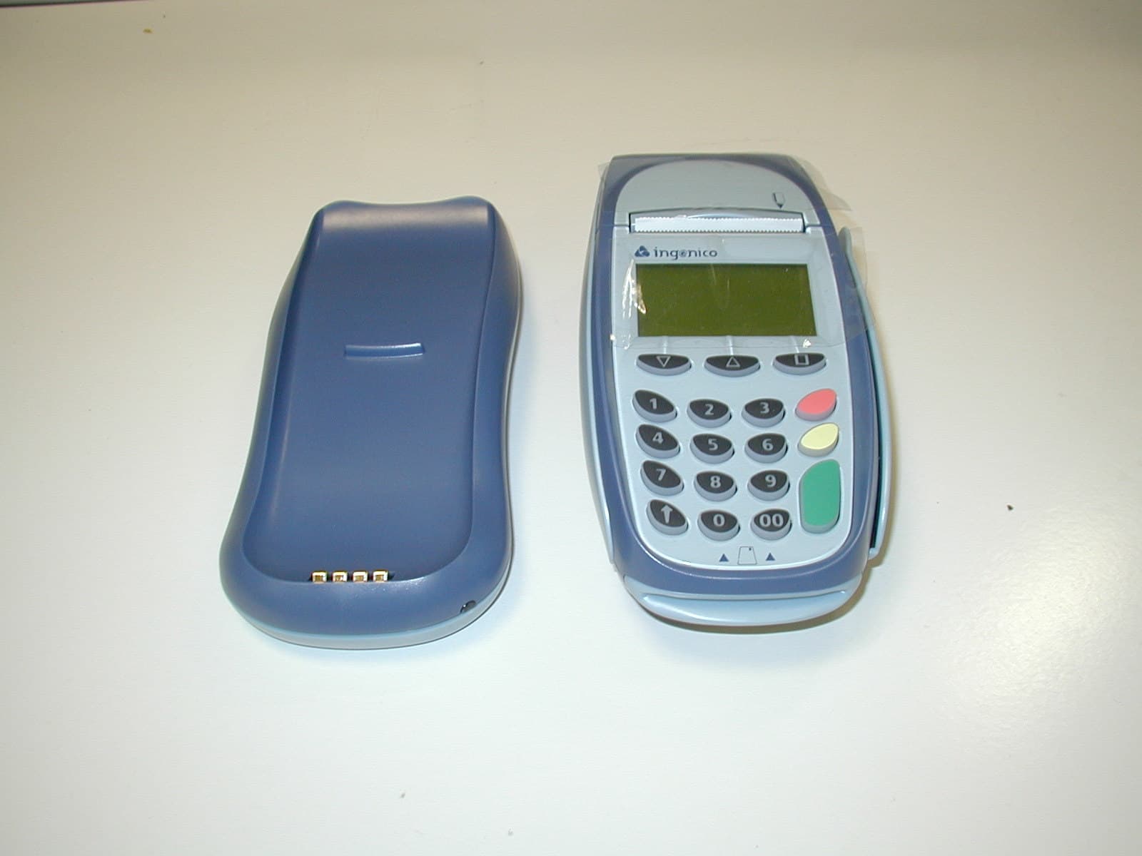
O34-I7770BASE
May 25, 2004Point of sale, base station
Equipment Class
DSS - Part 15 Spread Spectrum Transmitter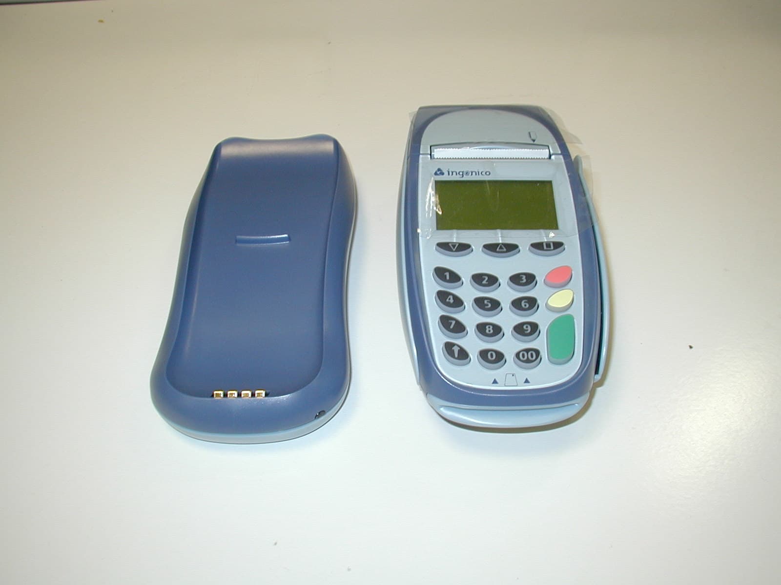
O34-I7770
May 05, 2004Point of sale hand held terminal
Equipment Class
DSS - Part 15 Spread Spectrum Transmitter