O34-ELITE780MXElite 780 MOBITEX
Ingenico
Click to zoom
Application Details
- Equipment Class
- TNB - Licensed Non-Broadcast Station Transmitter
- Date of Grant
- Mar 14, 2001
- Application Purpose
- Original Equipment
- Date of Application
- Dec 07, 2000
- Equipment Note
- Elite 780 MOBITEX
- Frequency Range
- 896.00000000 - 901.00000000
- Company
- Ingenico
- Country
- Canada
Documents & Files
Document Text
Text extracted from the exhibit documents filed with the FCC. Open a document above to read the original.
Users Manual
1003 Mansell Road ∑ Atlanta, GA 30076 tel: 770.594.6000 ∑ fax 770.594.6003 79 Torbarrie Road ∑ Toronto, Ontario, Canada M3L 1G5 tel:416.245.6700 ∑ fax: 416.245.6701 www.ivicheckmate.com 6.3 Power supply: The power adapter is mainly used for charging the internal NiCd battery. Power input voltage : 120V AC. Power input frequency : 60 Hz. Power output : 12V DC, 500mA. Figure 4: DC Plug 6.4 Operating environment Operating temperature : 5 to 40°C Humidity : 5% to 90% RH, with no condensation. 7.0 Thermal Paper Specification: The following specifications identify the thermal paper roll that is used with Elite 780 terminals: • Single ply thermal sensitive - POS or facsimile grade. • Thickness: .009 in (0.25 mm) maximum. • Roll Width: 2.25 +/- 0.020 in (58 mm +/- 0.5 mm). • Roll Diameter: 2.0 in (51 mm) maximum. • Roll Core ID: 0.500 in (13 mm) nominal. • Roll Core OD: 0.625 in (16 mm) nominal. 8. If you experience trouble : Call one of the customer service centers listed below: In Canada: In the USA: RBA Inc. IVI Checkmate Inc. 3190 Orlando Drive TotalCARE Mississauga, Ontario 1335 North Meadow L4V 1R5 Parkway, Suite 116 1-800-387-3938 Atlanta GA 30076 or (905) 672-1048 1-800 – 435-3014 US Federal Communications Commission (FCC) Warnings: This equipment has been tested and found to comply with the limits for a Class A digital device, pursuant to Part 15 of the FCC Rules. These limits are designed to provide reasonable protection against harmful interference when this equipment is operated in a commercial environment. This equipment generates, uses, and can radiate radio frequency energy and, if not installed and used in accordance with the instruction manual, may cause harmful interference to radio communications. Operation of this equipment in a residential area is likely to cause harmful interference in which case the user will be required to correct the interference at his own expense. Canadian Department of Communications (DOC) Warnings: This digital apparatus does not exceed the Class A limits for radio noise emissions from the digital apparatus as set out in the radio interference regulations of the Canadian Department of Communications. Elite 780 Installation Guide 0130-07056-0300 1. Terminal description: 1.1 Introduction: The Elite 780 is a fully self-contained RF EFTPOS terminal with an integrated printer and the functionality to process all smart card, debit and credit purchases. The terminal communicates with the bank using the RF data network. This network is similar to that used for mobile phones except that it is for data only. The terminal features a secure, multi-application operating system, which allows a number of different applications to run on the terminal independently, without jeopardizing software security. 1.2 The Terminal: The Elite 780 terminal has the following peripherals: 1.2.1 Display: Standard 4 line x 16 character LCD graphic display, with back lighting. 1.2.2 Keypad: • 18 keys, with back lighting, with the following special function keys: • F1, F2, and F3 keys: Programmable keys which permit access to terminal level functions and the system menu. • Paper Feed key: Performs a 20mm paper feed. • ENTER key: is used to confirm the data entered or displayed. • CAN key: is used to cancel the current function and return the terminal to the idle state. • CORR key: is used to correct any invalid data entry. • ADMIN key: is used to access the terminal administration function menu. 1.2.3 Magnetic Stripe Card Reader: This is a bi-directional reader capable of simultaneously reading Tracks 1&2, and is located just above the display. 1.2.4 Modem: The Modem facilitates data exchange over an RF network. 1.2.5 Printer: The built-in printer is a high-speed thermal printer (4 lines per second) and is graphics compatible. 1.2.6 Smart Card Reader: Complies with standard ISO 7816, Sync & Async. 1.3 Package contents are as follows: 1. The Elite 780 terminal. 2. RF antenna. 3. Wall mount power adapter for charging the NiCd battery. 4. Thermal printer paper, one roll. 5. Installation guide. 2. Installation procedure: A Important Note: The battery must be charged for 24 hours before using the terminal for any purpose including key injection, program loading or customer use. (See Paragraph 2.3) 2.1 Paper loading (If required): 1. Open the paper compartment cover. 2. Move the paper load lever forward to disengage the friction roller. 3. Remove the empty paper roll by pressing the roll release lever on the right hand side. 4. Position the paper roll with the end of the roll protruding from UNDERNEATH the roll. 5. Feed the paper under the printer’s roller until it protrudes from the top of the printer. 6. Fit the paper roll to the spindle and move the paper load lever back to engage the friction roller. 7. Close the cover and test the operation of the printer by pressing Paper Feed key. 2.2 Connecting the RF antenna: 1. Place the RF antenna connector over the coaxial screw mount located on the back panel. Make sure the wire within the connector fits into the small hole in the coaxial mount. 2. Tighten the connector by turning the antenna attachment clockwise. 2.3 Battery charging procedure: 2.3.1 At Installation: 1. After unpacking it is important to provide an initial charge. This conditioning cycle is required for the battery pack to reach full capacity quickly. 2. Connect the terminal to AC power using the supplied power pack designed for this terminal. You will know the terminal is receiving AC power when the display stays on continuously. The terminal must be charged continuously for 24 hours. A Make sure that you use the correct AC power adapter supplied with the terminal. Many adapters can appear similar and will plug into the terminal but will not work properly causing erratic behavior, poor charging or even damage to the unit. 2.3.2 Normal use: A 1. After a full charge the Terminal in normal usage is expected to provide 50 or more transactions before a recharge is required. Slow …
Text truncated - open the document above for the full version.
Cover Letter(s)
UltraTech Group of Labs Decembe 7, 2000 FEDERAL COMMUNICATIONS COMMISSION 7435 Oakland Mills Road Columbia, MD 21046 USA Subject: Type Acceptance Application under FCC CFR 47, Parts 2 and 90 (Subpart I) - Radio Services Transmitters Operating in the frequency band 896-901 MHz Applicant: IVI Checkmate Inc. Product: Elite 780 MOBITEX Model: Elite 780 MOBITEX FCC ID: O34-ELITE780MX Dear Sir/Madam, As appointed agent for IVI Checkmate Inc., we would like to submit the application to Federal Communications Commission for certification of the above product. Please review all necessary files uploaded to FCC OET site. The Elite 780 MOBITEX is a handheld Point of Sale, which incorporates the RIM 900 radio modem module Model R900-2 (FCC ID: L6AR900-2). The incorporated radio is identical in design and construction to the original. In this application an Elite 780 MOBITEX SAR test report is submitted for compliance. For information about the radio modem module please refer to RIM’s submission FCC ID L6AR900-2. If you have any queries, please do not hesitate to contact us by our TOLL FREE number: OUR TELEPHONE NO.: 1-877-765-4173 Yours truly, Tri Minh Luu, P. Eng., V.P., Engineering TML/AK 2 3000 Bristol Circle, Oakville, Ontario, Canada L6H 6G4 Telephone (905) 829-1570 Facsimile (905) 829-8050 IVI CHECKMATE Inc., 79 Torbarrie Road, Toronto, Ontario M3L 1G5 ♦ Tel: [416] 245-6700 ♦Fax: [416] 245-6701 Wednesday, November 23, 2000 FEDERAL COMMUNICATIONS COMMISSION 7435 Oakland Mills Road Columbia, MD 21046 U.S.A. Subject: Authority to Act as an Agent Applicant: IVI Checkmate Inc. Product: Elite 780 MOBITEX Model: Elite 780 MOBITEX FCC ID: O34-ELITE780MX Dear Sir/Madam, I hereby appoint UltraTech Engineering Labs Inc. (UltraTech) to act as my agent in preparation of this application to F.C.C. for authorization of equipment under F.C.C. Rules. I also certify that the information provided, properly described the device or system for which authorization is required. Regards By: Ayman Sydhom Engineering Technical Support
External Photos
EXTERNAL EUT PHOTOS IVI Checkmate Inc. Elite 780 MOBITEX, Model Elite 780 MOBITEX FCC ID: O34-ELITE780MX Photo 1 of 6 EXTERNAL EUT PHOTOS IVI Checkmate Inc. Elite 780 MOBITEX, Model Elite 780 MOBITEX FCC ID: O34-ELITE780MX Photo 2 of 6 EXTERNAL EUT PHOTOS IVI Checkmate Inc. Elite 780 MOBITEX, Model Elite 780 MOBITEX FCC ID: O34-ELITE780MX Photo 3 of 6 EXTERNAL EUT PHOTOS IVI Checkmate Inc. Elite 780 MOBITEX, Model Elite 780 MOBITEX FCC ID: O34-ELITE780MX Photo 4 of 6 EXTERNAL EUT PHOTOS IVI Checkmate Inc. Elite 780 MOBITEX, Model Elite 780 MOBITEX FCC ID: O34-ELITE780MX Photo 5 of 6 EXTERNAL EUT PHOTOS IVI Checkmate Inc. Elite 780 MOBITEX, Model Elite 780 MOBITEX FCC ID: O34-ELITE780MX Photo 6 of 6
ID Label/Location Info
IVI CHECKMATE Inc., 79 Torbarrie Road, Toronto, Ontario M3L 1G5 ♦ Tel: [416] 245-6700 ♦Fax: [416] 245-6701 The Following diagrams show the format and location of Elite 780 MOBITEX product label on the terminals. Model : ELITE 780-MOBITEX Modele: ELITE 780- MOBITEX Power: 12VDC / 500mA Alimentaiton: 12VDC / 500mA This device complies with Part 15 of the FCC rules. Operation is subject to The following two conditions: (1) This device may not cause harmful interference and (2) This device must accept any interference received, including interference That may cause undesired operation. This device contains a Research In Motion Wireless Modem registered as Follows: Model#: RIM PRD-01798-011 FCC ID: O34-ELITE780MX CANADA: Made in E.U. Fabrique en U.E Diagram 1: Format and text of Elite 780 MOBITEX Product Label Label Specifications: • IVI Part Number: 2416-00406-0200 • Size: 49mm x 47mm • Material: White vinyl • Text: Black Elite 780 MOBITEX product label Diagram 2: Position of Product label and Serial number barcoded label on Elite 780 MOBITEX unit. Printed Name: Ayman Sydhom Date: November 23, 2000 Signature: Engineering Technical Support
Internal Photos
INTERNAL EUT PHOTOS IVI Checkmate Inc. Elite 780 MOBITEX, Model Elite 780 MOBITEX FCC ID: O34-ELITE780MX Photo 1 of 14 INTERNAL EUT PHOTOS IVI Checkmate Inc. Elite 780 MOBITEX, Model Elite 780 MOBITEX FCC ID: O34-ELITE780MX Photo 2 of 14 INTERNAL EUT PHOTOS IVI Checkmate Inc. Elite 780 MOBITEX, Model Elite 780 MOBITEX FCC ID: O34-ELITE780MX Photo 3 of 14 INTERNAL EUT PHOTOS IVI Checkmate Inc. Elite 780 MOBITEX, Model Elite 780 MOBITEX FCC ID: O34-ELITE780MX Photo 4 of 14 INTERNAL EUT PHOTOS IVI Checkmate Inc. Elite 780 MOBITEX, Model Elite 780 MOBITEX FCC ID: O34-ELITE780MX Photo 5 of 14 INTERNAL EUT PHOTOS IVI Checkmate Inc. Elite 780 MOBITEX, Model Elite 780 MOBITEX FCC ID: O34-ELITE780MX Photo 6 of 14 INTERNAL EUT PHOTOS IVI Checkmate Inc. Elite 780 MOBITEX, Model Elite 780 MOBITEX FCC ID: O34-ELITE780MX Photo 7 of 14 INTERNAL EUT PHOTOS IVI Checkmate Inc. Elite 780 MOBITEX, Model Elite 780 MOBITEX FCC ID: O34-ELITE780MX Photo 8 of 14 INTERNAL EUT PHOTOS IVI Checkmate Inc. Elite 780 MOBITEX, Model Elite 780 MOBITEX FCC ID: O34-ELITE780MX Photo 9 of 14 INTERNAL EUT PHOTOS IVI Checkmate Inc. Elite 780 MOBITEX, Model Elite 780 MOBITEX FCC ID: O34-ELITE780MX Photo 10 of 14 INTERNAL EUT PHOTOS IVI Checkmate Inc. Elite 780 MOBITEX, Model Elite 780 MOBITEX FCC ID: O34-ELITE780MX Photo 11 of 14 INTERNAL EUT PHOTOS IVI Checkmate Inc. Elite 780 MOBITEX, Model Elite 780 MOBITEX FCC ID: O34-ELITE780MX Photo 12 of 14 INTERNAL EUT PHOTOS IVI Checkmate Inc. Elite 780 MOBITEX, Model Elite 780 MOBITEX FCC ID: O34-ELITE780MX Photo 13 of 14 INTERNAL EUT PHOTOS IVI Checkmate Inc. Elite 780 MOBITEX, Model Elite 780 MOBITEX FCC ID: O34-ELITE780MX Photo 14 of 14
RF Exposure Info
Elite 780 MOBITEX Model No.: Elite 780 MOBITEX Tested For IVI CHECKMATE Inc. 79 Torbarrie Road Toronto, Ontario Canada, M3L 1G5 In Accordance With SAR (Specific Absorption Rate) Requirements using guidelines established in IEEE C95.1-1991, FCC OET Bulletin 65 (Supplement C), Industry Canada RSS-102 (ssue 1) and ACA Radiocommunications (Electromagnetic Radiation – Human Exposure) Amendment Standard 2000 (No. 1) UltraTech's File No.: IVI-077-SAR This Test report is Issued under the Authority of Tri M. Luu, Professional Engineer, Vice President of Engineering UltraTech Group of Labs Date: December 1, 2000 Report Prepared by: Carolyn LuuTested by: JaeWook Choi Issued Date: December 1, 2000Test Dates: November 9, 2000 The results in this Test Report apply only to the sample(s) tested, which has been randomly selected. UltraTech 3000 Bristol Circle, Oakville, Ontario, Canada, L6H 6G4 Telephone (905) 829-1570 Facsimile (905) 829-8050 Website: www.ultratech-labs.com Email: [email protected] SPECIFIC ABSORPTION RATE (SAR)Page 1 IEEE C95.1-1991, FCC OET Bulletin 65 (Supplement C), Industry Canada RSS-102(Issue 1) and ACA Radiocommunications (Electromagnetic Radiation – Human Exposure) Amendment Standard 2000 (No. 1) Elite 780 MOBITEXModel No.: Elite 780 MOBITEX ULTRATECH GROUP OF LABS File #: IVI-077-SAR 3000 Bristol Circle, Oakville, Ontario, Canada L6H 6G4December 1, 2000 Tel. #: 905-829-1570, Fax. #: 905-829-8050, Email: [email protected], Website: http://www.ultratech-labs.com • Assessed by ITI (UK) Competent Body, NVLAP (USA) Accreditation Body & ACA/AUSTEL (Australia), VCCI (Japan) • Accredited by Industry Canada (Canada) under ACC-LAB (Europe/Canada MRA and APEC/Canada MRA) • Recognized/Listed by FCC (USA ) • All test results contained in this engineering test report are traceable to National Institute of Standards and Technology (NIST) TABLE OF CONTENTS EXHIBIT 1. INTRODUCTION.............................................................................................................................................. 3 1.1.SCOPE......................................................................................................................................................................... 3 1.2.REFERENCES ............................................................................................................................................................ 3 EXHIBIT 2. PERFORMANCE ASSESSMENT................................................................................................................... 4 2.1.CLIENT AND MANUFACTURER INFORMATION ............................................................................................... 4 2.2.DEVICE UNDER TEST (DUT) DESCRIPTION....................................................................................................... 4 2.3.SPECIAL CHANGES ON THE DUT’S HARDWARE/SOFTWARE FOR TESTING PURPOSES ........................ 5 2.4.ANCILLARY EQUIPMENT ...................................................................................................................................... 5 2.5.GENERAL TEST CONFIGURATIONS .................................................................................................................... 5 2.5.1.Equipment Configuration .................................................................................................................................... 5 2.5.2.Exercising Equipment .......................................................................................................................................... 5 2.6.S PECIFIC O PERATING C ONDITIONS ................................................................................................................................5 2.7.BLOCK DIAGRAM OF TEST SETUP ...................................................................................................................... 6 EXHIBIT 3. SUMMARY OF TEST RESULTS ................................................................................................................... 7 3.1.LOCATION OF TESTS .............................................................................................................................................. 7 3.2.APPLICABILITY & SUMMARY OF SAR RESULTS ............................................................................................. 7 EXHIBIT 4. MEASUREMENTS, EXAMINATIONS & TEST DATA .............................................................................. 8 4.1.TEST SETUP .............................................................................................................................................................. 8 4.2.P HOTOGRAPH OF EUT .................................................................................................................................................. 9 4.3.PHOTOGRAPHS OF EUT POSITION .................................................................................................................... 11 4.4.\MAXIMUM FIELD LOCATION (R EF . TO P . 14).................................................................................................... 13 4.5. PEAK SPATIAL - AVERAGE SAR MEASURED .................................................................................................................... 14 4.6. SAR M EASUREMENT DATA....................................................................................................................................... 14 EXHIBIT 5. SAR SYSTEM CONFIGURATION & TEST METHODOLOGY ............................................................. 15 5.1.M EASUREMENT S YSTEM S PECIFICATIONS .................................................................................................................. 15 5.2.T EST P ROCEDURES ..................................................................................................................................................... 15 5.3.P HANTOM ............................................…
Text truncated - open the document above for the full version.
RF Exposure Info
Answer to FCC Questions Q3: The original filing for the transmitter module and the cover letter provided by Research in Motion have not indicated this transmitter cannot operate at less than 100% duty factor and SAR has been tested at 100% duty factor. It is unclear whether the timing plots provided by the applicant are based on the Mobitex transmission protocol, where the duty factors are operation based therefore do not qualify for source- based time-averaging considerations, or if the timing plots are based on other considerations. Please clarify with more detailed explanations on how the timing sequences shown on the plots are derived in order for us to determine if they can be accepted for source-based time-averaging considerations. The applicant may want to consult with the transmitter module manufacturer (Research in Motion) regarding applicable source-based time-averaging considerations. A3: 1. IVICM’s handheld radio implements a duty cycle limiting algorithm to inhibit the radio from transmitting at all times when a fixed duty cycle limit could be exceeded. This duty cycle limiting algorithm is implemented in firmware which is permanently installed in the handheld during production process in the factory. Once installed in the handheld, the user cannot change, or disable this firmware algorithm. This firmware algorithm measures the transmit ON time, and the transmit OFF time. From these data, it calculates the current duty cycle by dividing the ON time by the sum of the ON time, and OFF time. Before it enables the radio to transmit, it first calculates the would-be duty cycle based on the total length of the packet it has to send. If this would-be duty cycle could exceed the fixed limit, it will not enable radio transmission until the transmit OFF time has accumulated so much that it can guarantee the would-be duty cycle will not exceed the fixed limit. Since this algorithm performs both real-time measurement, and advance duty cycle calculation, it can ensure that the operating duty cycle is less than the fixed limit at all times to provide a safety margin. The duty cycle limit is fixed at 15%, which is permanently stored in firmware, and cannot be modified, or disabled by the user. This 15% limit is less than the 20% that is required of IVICM’s handheld based on 100% duty cycle SAR measurement of the handheld. 2. IVICM has tested this firmware algorithm at UltraTech. The timing plots were part of the results from the testing, which were measurements based on the Mobitex transmission protocol. The timing plots serve the purpose of having verified that the measurement, and duty cycle calculation performed by this algorithm are valid. The testing at UltraTech also verified that no RF transmission was measured by the test equipment when this algorithm inhibited radio transmission at the point when the duty cycle could be exceeded. Q4: Please confirm that this device is designed for hand-held used only, to be operated in a person's hands, and there are no body-worn operating provisions. If the low duty cycle is not applicable, operating instructions should be included in the users manual to inform users of the specific hand-held operating requirements for meeting FCC RF exposure compliance. A4: This device is designed hand-held use only, and following is the sequence of steps required to process a transaction: 1. Hold the unit in the hand and press the <Enter> Key to power up the terminal (The terminal is automatically turned off when left in idle mode). 2. Start a transaction by swiping the customer card. 3. Hand the unit to the customer to enter TIPS and the PIN number if required. After the customer enters this information, transmission of information to the RF network begins. 4. As soon as the terminal receives transaction approval, it prints the receipt. 5. The operator turns off the terminal. If the operator does not, the terminal will automatically power down. - As mentioned above, the terminal needs human intervention to operate. There is no auto power up feature or background activity that would power up the terminal without operator intervention.
Test Report
CFR 47 Chapter 1 - Federal Communication Commission Rules Part 2 Required Measurement 2.985 (a,c)RF Power Output Part 90 Subpart I : Technical Standards 90.205RF Power Output (a)Request no more power than neccessary for satisfactory operation. (b)Maximum power output limit : reference to subpart S (896-901 MHz band). (c)exced by no more than 20% manufacturer’s rated output power. Part 90 - Subpart S : Use of Frequencies in 896-901 MHz Band 90.635Limitations on Output Power - 100W 20dbw (d)Mobile station maximum output power is 100 W (20dBW) We are requesting and rating the device as 2 W (33 dBm) output across a 50 ohm load. Limit on device output power would be 120% of 2 W which is 2.4 W (33.8 dBm). Calibrated power measurement using the following equipment: HP 437B Power MeterS/N 3125U10666 Cal due 19/05/96 HP 8482A Power SensorS/N 3318A24237 Cal due 23/05/96 HP 4396A Network Analyzer S/N 3241J00180 Cal due 23/05/96 HP 85046A S-Parameter Test SetS/N 3033A06051Cal due 23/05/96 HP 85033C Calibration KitS/N 2920A02997 Cal due 30/05/96 Omni Spectra 3082-6194-20 DC to 18 Ghz Coaxial Attenuator Procedure: These results were obtained using the test procedure described in document DOC-1547-013. The 4396A and 85046A were calibrated using the 85033C. The cable assembly and microwave attenuator used for the measurements were calibrated using the 4396A and the 85046A. The 437B and 8482A were calibrated using the internal power reference. The radio was tuned by the procedure as provided for sections 2.983(d)(5) and 2.983(d)(9). At three transmit frequencies the maximum radio output power level was measured after 1 minute of continuous operation using the 437B and 8482A. Output levels were measured for both modulated and unmodulated carrier. The calibrated insertion loss measured for the attenuator and cable assembly was added to the calibrated power measurements which produced the following results: Limit:2.4 W (33.8 dBm) Results:CarrierMeasuredCalibratedOutputOutput FrequencyLevelAttenuationPowerPower 896.000 MHz7.32 dBm25.67 dB32.99 dBm 1.991 W 899.000 MHz7.34 dBm25.67 dB33.01 dBm 2.000 W 902.000 MHz7.32 dBm25.67 dB32.99 dBm 1.991 W Identical output power levels were recorded for both modulated and unmodulated carrier CFR 47 Chapter 1 - Federal Communication Commission Rules Part 2 Required Measurement 2.983Frequency Stability - Procedures (a,c)Frequency Stability - Temperature Variation (d)Frequency Stability - Voltage Variation Part 90 Subpart I : Technical Standards 90.213Frequency Tolerance (a)Maintain the carrier frequency within 0.00015 % (1.5 ppm) of the assigned frequency. (b)Maximum power output used for measurement Frequency and power measurements were performed together with the same set up. Frequency and power data were both recorded across temperature and voltage. The set up used a cable assembly with a power splitter to allow concurrent measurements with the frequency counter and the power meter. The cable assembly was calibrated to allow compensation of the insertion loss between the transmitter and the power meter. Calibration for the Cable and Attenuator Loss: Place: RF Lab in RIM. Date: 18th July 95 Time: 0800 Hrs. Equipment: InstrumentSerial NumberCalibrated on Network Analyzer HP 4396A3241J0018023.05.95 Calibration Kit HP85033C2920A0299730.05.95 S-Parameter Test set HP85046A3033A0605123.05.95 Procedure: Full Two port Calibration of 4396A and 85046A using the 85033C was done. An assembly of Cables, Attenuator, power splitter, and connectors was made as shown below for making RF power measurements. Attenuator: 20dB, DC to 18 Ghz - Omni Spectra part no: 3082-6194-20 Power splitter: 3dBMCL part no: ZN2PD-920W 9401 02 The total loss of this cable assembly from the RF input to the RF output was measured to be 25.67 dB. at 899 +/- 3Mhz. Power and frequency measurements of RIM 900 Radio at different temperatures: Place: AIT Lab at COMDEV Date: 18th July 95 to 20th July 95 Equipment: InstrumentSerial numberCalibrated on DC Power supply HP E3610AKR30706270 Frequency Counter HP 5331A3325A0098819.05.95 RF Power meterHP 437B3125U1066619.05.95 RF Power sensorHP 8482A3318A2423723.05.95 Temperature Chamber: Manufacturer: Cincinnati Subzero Products Model: BZ-1.6-033-033-H/AC Serial No: ZA9211523 Calibrated on: May 95. Procedure: The RIM 900 Radio and the Interface board were placed in the Temperature chamber and connected to the instruments outside as shown in the figure below. Dry nitrogen was pumped inside the temperature chamber to maintain a back pressure during the test. The Radio was kept in the off condition at all times except when the measurements were to be made. The chamber was switched on and the temperature was set to +50 deg C. After the chamber stabilized at +50 deg C a 40 minute soak was given to ensure that all moisture is driven out. The temperature was then set to -30 deg C. After the temperature stabilized at -30degCa2Hrsoakwasgiven. The Radio was switched on and Frequency and power measurements were made as follows: The Power supply was adjusted to the required value. The RIM Radio test utility was run on the computer and the Type Testing Options window was used to set the frequency & power and to switch on / off the carrier. The software “gf” in the directory C:\01605 was run under DOS prompt to read the HP 5331A frequency counter using the HPIB Bus. The software timestamps the measurements for a period of 60 seconds and stores the data in a file. The RF power measurement was made manually. As the power varies with time, it was noted at the beginning and the end of each test The software utility produces tab delimited data files numbered sequentially. All data from this test has been formatted from the initial files into a single Spreadsheet. The temperature and soak times followed were as follows: After the soak of 2hrs at -30 deg C the measurements were made for 6.0 Volts operation at the 3 frequencies. Then a 15 minute soak was given and the measurements were repeated …
Text truncated - open the document above for the full version.
Test Report
Effective Radiated Power TEST METHOD ß The following shall be applied to the combination(s) of the radio device and its intended antenna(e). ß If the RF level is user adjustable, all measurements shall be made with the highest power level available to the user for that combination. ß The following method of measurement shall apply to both conducted and radiated measurements. ß The radiated measurements are performed at the Ultratech Calibrated Open Field Test Site. ß The measurement shall be performed using normal operation of the equipment with modulation. Test procedure shall be as follows: Step 1: Duty Cycle measurements ÿ Using a spectrum analyzer with the frequency span set to 0 Hz and the sweep time set at a suitable value to capture the envelope peaks and the duty cycle of the transmitter output signal; ÿ The duty cycle of the transmitter, x = Tx on / (Tx on + Tx off) with 0<x<1, is measure and recorded in the test report. For the purpose of testing, the equipment shall be operated with a duty cycle that is equal or more than 0.1. Step 2: Calculation of Peak and Average EIRP ÿ The peak output power of the transmitter shall be determined using a wideband, calibrated RF Peak Power Meter with the power sensor with an integration period that exceeds the repetition period of the transmitter by a factor 5 or more. The observed value shall be recorded as “P” (in dBm); ÿ The Average EIRP. shall be calculated from the above measured power output “A”, the observed duty cycle x, and the applicable antenna assembly gain “G” in dBi, according to the formula: Peak EIRP = P + G Average EIRP = Peak EIRP + 10log(1/x) Figure 1. Step 3: Substitution Method. See Figure 2 (a) The measurements was performed in the absence of modulation (un-modulated) (b) Test was performed at listed 3m open area test site (listed with FCC, IC, ITI, NVLAP, ACA & VCCI). (c) The transmitter under test was placed at the specified height on a non-conducting turntable (80 cm height) (d) The dipole test antenna was used and tuned to the transmitter carrier frequency. (e) The spectrum analyzer was tuned to transmitter carrier frequency. The test antenna was lowered or raised from 1 to 4 meters until the maximum signal level was detected. (f) The transmitter was rotated through 360 o about a vertic…
Text truncated - open the document above for the full version.
Contact Information
Applicant
Kandeepan K.
(416) 245-6700Fax: (416) 245-6701
Technical Contact
Ultratech Engineering Labs Inc.Tri M Luu
[email protected]1-877-765-4173
3000 Bristol Circle · Oakville, Ontario · Canada
Non-Technical Contact
Ultratech Engineering Labs Inc.Tri M Luu
[email protected]1-877-765-4173
Test Firm
UltraTech Engineering Labs Inc.Tri Luu
Technical Specifications
| # | Rule Parts | Frequency Range | Power Output | Emission | Tolerance |
|---|---|---|---|---|---|
| 1 | 90 | 896 MHz - 901 MHz | 1.07 W | 10K0F1D | 0.0001500000 % |
Other Applications from Ingenico

O34-CPEM-E1K6567
Aug 25, 2005CONTACTLESS PAYMENT EXPANSION MODULE
Equipment Class
DXX - Part 15 Low Power Communication Device Transmitter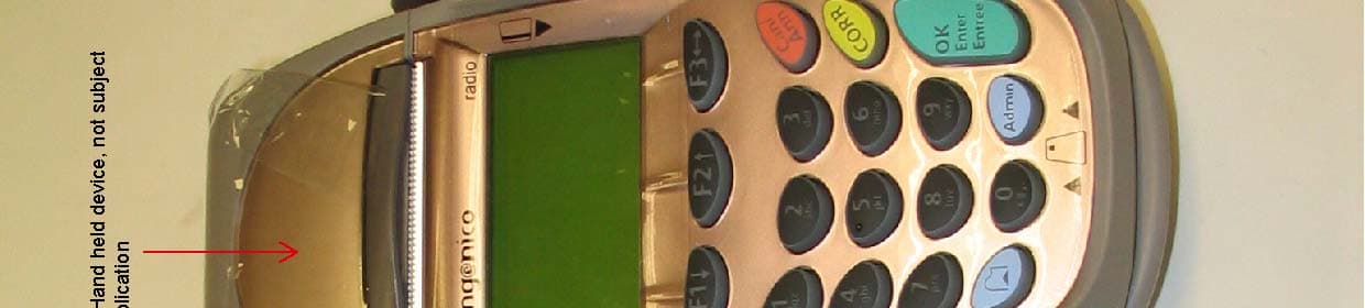
O34-I7770RBBT2
Jun 16, 2005Point of Sale, Base Station
Equipment Class
DSS - Part 15 Spread Spectrum Transmitter
O34-I7770BT2
Jun 16, 2005Point of Sale, Hand held Terminal
Equipment Class
DSS - Part 15 Spread Spectrum Transmitter
O34-GPRS
Nov 01, 2004ELITE 790 GPRS POINT OF SALE TERMINAL
Equipment Class
PCT - PCS Licensed Transmitter worn on body
O34-I7770BASE
May 25, 2004Point of sale, base station
Equipment Class
DSS - Part 15 Spread Spectrum Transmitter