O44J2000RTransceiver of Car Alarm/Remote Engine Starter
Youngshin Electronics Co., LTD.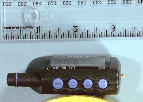
Click to zoom
Application Details
- Equipment Class
- DSR - Part 15 Remote Control/Security Device Transceiver
- Date of Grant
- Aug 31, 2000
- Application Purpose
- Original Equipment
- Date of Application
- Aug 31, 2000
- Equipment Note
- Transceiver of Car Alarm/Remote Engine Starter
- Frequency Range
- 447.70000000 - 447.70000000
- Country
- South Korea
Documents & Files
Document Text
Text extracted from the exhibit documents filed with the FCC. Open a document above to read the original.
Users Manual
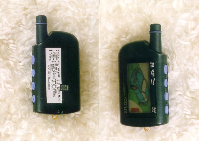
Page 1 of 8- 1 - CompuStar 2000AS USER’S GUIDE Firstech, Inc. 801 E. 82 nd Ave Suite 1 Anchorage AK. 99518 (907) 563-8648 This device complies with Part 15 of the FCC Rules. Operation is subject to the following two conditions: (1) This device ma y not ca use har mful interference, and (2) this device must accept any interference received, including interference that may cause undesired operation. CAUTION: Changes or modifications not expressly approved by the party responsible for compliance could void the user’s authority to operate this device. This equipment has been tested and found to comply with the limits for a Class B digital device, pursuant to Part 15 of the FCC Rules. These limits are designed to provide reasonable protection against harmful interference in a residential installation. This equipment generates, uses and can radiate radio frequency energy and, if not installed and used in accordance with the instructions, may cause harmful interference to radio communications. However, there is no guarantee that interference will not occur in a particular installation. If this equipment does cause harmful interference to radio or television reception, which can be determined by turning the equipment off and on, the user is encouraged to try to correct the interference by one or more of the following measures: • Reorient or relocate the receiving antenna. • Increase the separation between the equipment and receiver. • Connect the equipment into an outlet on a circuit different from that to which the receiver is connected. • Consult the dealer or an experienced radio/TV technician for help. Page 2 of 8- 2 - INTRODUCTION Thank you for choosing COMPUSTAR, a state-of-the-art TWO WAY alarm/remote start systems for your vehicle. We, at FIRSTECH, INC., are constantly researching and developing to make you and your vehicle safe and more comfortable. SECURITY & COMFORT, that’s what FIRSTECH, INC. is all about. TABLE OF CONTENTS 1. Transmitter Button functions ---------------------------------------------------Page 3 2. Alarm Function------------------------------------------------------------------------Page 3 3. Panic-------------------------------------------------------------------------------------Page 3 4. Start Function--------------------------------------------------------------------------Page 3 5. Safety Shutdown----------------------------------------------------------------------Page 4 6. VPS(Vehicle Paging System)------------------------------------------------------Page 4 7. Aux 1 and Aux 2-----------------------------------------------------------------------Page 4 8. Valet Mode and Valet Switch------------------------------------------------------Page 4 9. Shock Sensor--------------------------------------------------------------------------Page 4 10. Timer Start-----------------------------------------------------------------------------Page 4 11. 2 nd Car----------------------------------------------------------------------------------Page 4 12. Transmitter Learning Procedure-------------------------------------------------Page 4 13. Programming Options with Transmitter----------------------------------------Page 5 14. Warranty Statement-----------------------------------------------------------------Page 7 15. Registration Card---------------------------------------------------------------------Page 8 Page 3 of 8- 3 - 1. T ransmitter Button Functions Channel ButtonPress for FunctionFactory Setting 1.I1/2 secArm/Disarm; VPS on/off 2.II1/2 secAux 1 3.III1/2 secAux 2 4.IV1/2 secQuery 5.I -2 secPanic 6.II -2 secRemote Starting - On/Off 7.III-2 secTrunk 8.IV-2 secCompuGlo Back Light On/OffOn 9.(I+II)1/2 secSiren Chip - On/OffOn 10.(I+III)1/2 secValet Mode - On/OffOff 11.(I+IV)1/2 secShock Sensor On/OffOn 12.(II+III)1/2 secTransmitter Beep - On/OffOn 13.(II+IV)1/2 secTimer Mode 1.5 hour - On/OffOff 14.(III+IV)1/2 sec2 nd CarOff 15.(I+II)-2 secOption Programming 1 16.(I+III)-2 secOption Programming 2 2. Alarm Function Upon arming, yo ur alarm will be triggered by: • Light Impact (first stage shock sensor). The siren will chirp 4 times and the parking lights will flash for a few seconds. The transmitter will be paged and the vibratio n icon will appear in the LCD. • Heavy impacts (second stage shock sensor). The siren will go off and the parking lights flash for 60 Seconds. The transmitter will be paged and the Hammer in the LCD will appear. • Door opened. The siren will go off and the parking lights will flash for 60 Seconds. The transmitter will be paged and the door icon will appear in the LCD. • If you have installed the Optional starter kill functio n, your vehicle will not start with key when system is armed. Note: (Siren duratio n 30Sec. or 60Sec. refer to programming section) 3. Panic In Case of an emergence and you want to track attentio n. Press Button I for 2 Seconds and you will enter Panic Mode. The siren will go off and the parking light will start flashing. To disengage Panic Mode. Press Button I for ½ Second. Page 4 of 8- 4 - 4. Start Function Press Butto n II for 2 Seconds to start the engine. The engine will start and give you a confirmation on the Remote-pager. The engine will run 15 minutes (25 min for diesel) or 25 minutes (40 min for diesel) . If the engine has a problem starting the system will retry 2 more times. If the engine dose not start after the 3 rd attempt, please call yo u Authorized Dealer. Note: Runtime, please co nsult yo u Authorized Dealer. 5. Safety Shut Down System has several Shut Down inputs. That will shut down the engine or prevent from remote starting. • the Hood is opened, • the Brake is pressed, • the Valet is entered, or • the Valet switch is turned on. 6. VPS(Vehicle Paging System) VPS is turned on upon arming. If the VPS sensor is triggered by an impact such as knocking on the VPS module, the transmitter will be paged. 7. Aux 1 & Aux 2 The system has Aux 1 & Aux 2 output to be utilized with optional features. (Consult your Auth…
Text truncated - open the document above for the full version.
Block Diagram
1.1 Block Diagram (B1(BLOCK1)~B23(BLOCK23)) RX : B1~B8 (RF receiving block) TX : B9~B15 (RF transmitting block) Logic : B16~B23 ANTENNA(for RX/TX) B1. Classify RX/antenna B11. First Filter B9. Modulation B10. Output Oscillator B7. Second Local Oscillation B8. FM-Demodulation IC B6. First middle frequency filter B5. First mixxer and middle frequency amplify B3. High frequcncy Filter B2. Low noise high-frequency amplify B17. Micro-Controller(KS57P21208) B18. Rf-Output Power enable/disable B19. Real time clock B16. Rf-Input enable/disable B20. L.C.D.- Display B21. Button- ,α,β,χ B22. DC/DC up-converter B23. +DC1.5V Battery B4. First Local Oscillation B15. Classify TX/antenna B14. Second Amplify B13. Second Filter B12. First Amplify
Block Diagram
1.1 Block Diagram (B1(BLOCK1)~B23(BLOCK23)) RX : B1~B8 (RF receiving block) TX : B9~B15 (RF transmitting block) Logic : B16~B23 ANTENNA(for RX/TX) B1. Classify RX/antenna (447.7)ΜΗζ B11. First Filter (447.7/9)ΜΗζ B9. Modulation B10. Output Oscillator B7. Second Local Oscillation (20.945)ΜΗζ B8. FM-Demodulation IC B6. First middle frequency filter B5. First mixxer and middle frequency amplify (21.4)ΜΗζ B3. High frequcncy Filter B2. Low noise high-frequency amplify B17. Micro-Controller(KS57P21208) B18. Rf-Output Power enable/disable B19. Real time clock (4)ΜΗζ B16. Rf-Input enable/disable B20. L.C.D.- Display B21. Button- ,α,β,χ B22. DC/DC up-converter B23. +DC1.5V Battery B4. First Local Oscillation (469.1)ΜΗζ B15. Classify TX/antenna (447.7)ΜΗζ B14. Second Amplify B13. Second Filter (447.7/3)ΜΗζ B12. First Amplify
Cover Letter(s)
Youngshin Electronics Co., Ltd. 4FL Hirun Town Bldg 536-3. Unhaeng-Dong. Sihung, K yungki-Do, The Republic of Korea, 429-060 Phone 82-31-314-4133 Fax 82-31-314-4130 Ema il yo ungs hin@ ma gicar.co m LETTER OF AUTHORIZATION July 26, 2000 To whom it may concern: We the undersigned, hereby authorize CKC Laboratories, Inc., to act on our behalf in all manners relating to application for equipment authorization, including signing of all documents relating to these matters. Any and all acts carried out by CKC Laboratories, Inc., on our behalf shall have the same affect as acts of our own. This authorization is valid until further written notice from Youngshin Electronics Co., Ltd. Sincerely, Young Il Chang President Youngshin Electronics Co., Ltd.
Cover Letter(s)
Youngshin Electronics Co., Ltd. 4FL Hirun Town Bldg 536-3. Unhaeng-Dong. Sihung, K yungki-Do, The Republic of Korea, 429-060 Phone 82-31-314-4133 Fax 82-31-314-4130 Ema il yo ungs hin@ ma gicar.co m LETTER FOR FCC’s DRUG COMPLIANCE STATEMENT DATE: July 26, 2000 Federal Communications Commission 7435 Oakland Mills Road Columbia, MD 21046 We the undersigned, hereby certify that, in the case of individual applicant, he or she is not subject to a denial of federal benefits pursuant to section 5301 of the Anti-Drug Abuse Act of 1988, 21 USC 853a or in the case of non-individual applicant (e.g. corporation, partnership or other unincorporated association), no party to the applicant is subject to a denial of federal benefit pursuant to that action. Sincerely, Young Il Chang President Youngshin Electronics Co., Ltd.
Operational Description
REMOTE ANTENNA DESCRIPTION The Compustar2000AS-R, the remote unit, has an antenna permanently attached Omni- directional Antennas.
Operational Description
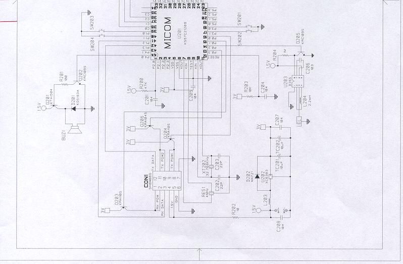
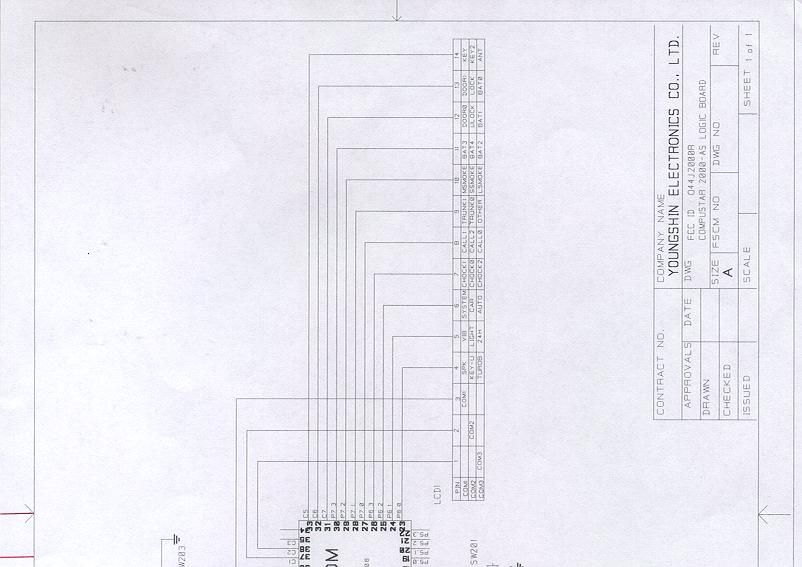
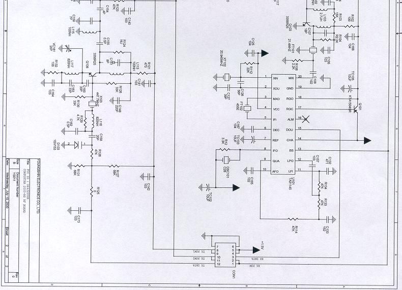
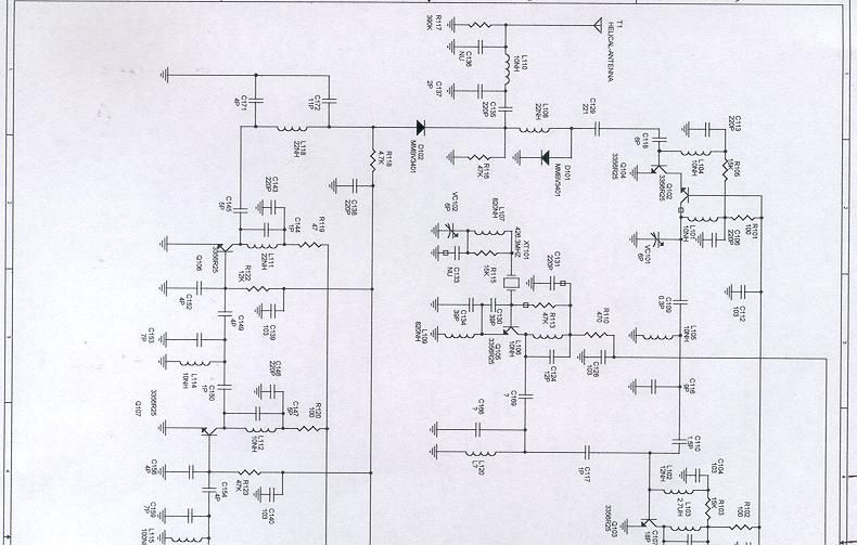
Description of the Electrical Circuitry Hand Held Transceiver O44J2000R A) When one or more of the buttons of the Transceiver is pressed: 1) When one or more of I, II, III or IV buttons is/are pressed, the button instruction is transferred to U201 (CPU). 2) U201 (CPU) transfers the ID code and button instruction to Q108 through R125. 3) Q108 generates the radio frequency carrier of 447.7 MHz that was modulated by the data from U201. 4) The signal from Q108 is amplified by the Transistor Q107, Q106, then sent to Antenna T1. B) When a signal enters from the antenna: 1) U201 (CPU) monitors the 447.7 MHz through Antenna T1. 2) When U201 receives 447.7 MHz signal, the signal is amplified by Transistor Q104, Q102, then sent to the Mixer Transistor Q103. 3) Q105 sends self-generated frequency 469.1 MHz to Mixer Transistor Q103. 4) Transistor Q103 heterodynes the signals from Q102 and Q105 to generate 21.4Mhz that is sent to Intermediate Frequency IC, U101. 5) Intermediate Frequency IC demodulate the signal to digital code and then send it to U201 (CPU). 6) The CPU recognizes the ID and instruction, then activates the Beeper Buz1 and indicates the information on the LCD1.
Operational Description
DESCRIPTION OF GROUND - REMOTE The remote uses AAA 1.4 volt batteres.
Test Report
Page 1 of 28 Report No: FC00-062 YOUNGSHIN ELECTRONICS CO., LTD. TEST REPORT FOR THE TRANSCEIVER OF CAR ALARM/REMOTE ENGINE STARTER, COMPUSTAR 2000AS-REMOTE (Only Transmitter Data In This Report) FCC PART 15 SUBPART C PART 15.231 COMPLIANCE DATE OF ISSUE: JULY 10, 2000 PREPARED FOR: Youngshin Electronics Co., LTD. 4 FL Hirun Town Bldg 536-3 Unhaeng-Dong Sihung, Kyungki-Do Korea 429-060 P.O. No: Wire transfer W.O. No: 74524 PREPARED BY: Joyce Walker CKC Laboratories, Inc. 5473A Clouds Rest Mariposa, CA 95338 Date of test: June 8-9, 2000 Report No: FC00-062 DOCUMENTATION CONTROL: _____________________________ Tracy Phillips Documentation Control Supervisor CKC Laboratories, Inc. APPROVED BY: _____________________________ Dennis Ward Director of Laboratories CKC Laboratories, Inc. This report contains a total of 28 pages and may be reproduced in full only. Partial reproduction may only be done with the written consent of CKC Laboratories, Inc. Page 2 of 28 Report No: FC00-062 TABLE OF CONTENTS Administrative Information ............................................................................................. 3 Summary Of Results........................................................................................................ 4 Equipment Under Test (EUT) Description...................................................................... 4 Measurement Uncertainty................................................................................................ 4 EUT Operating Frequency............................................................................................... 4 Peripheral Devices ........................................................................................................... 4 Report Of Measurements................................................................................................. 5 Table 1: Fundamental Radiated Emission Levels .............................................. 5 Table 2: Six Highest Radiated Emission Levels ................................................ 6 Table A : List Of Test Equipment ................................................................................... 7 EUT Setup .......................................................................................................................8 Test Instrumentation And Analyzer Settings................................................................... 8 Table B : Analyzer Bandwidth Settings Per Frequency Range........................... 8 Spectrum Analyzer Detector Functions............................................................... 9 Peak ......................................................................................................... 9 Quasi-Peak............................................................................................... 9 Average.................................................................................................... 9 Test Methods ................................................................................................................... 10 Radiated Emissions Testing................................................................................. 10 Transmit Times.................................................................................................... 10 Occupied Bandwidth ........................................................................................... 10 Sample Calculations ........................................................................................................ 11 Appendix A : Information About The Equipment Under Test........................................ 12 I/O Ports............................................................................................................... 13 Crystal Oscillators ............................................................................................... 13 Printed Circuit Boards ......................................................................................... 13 Required EUT Changes To Comply.................................................................... 13 Photograph Showing Radiated Emissions ........................................................... 14 Photograph Showing Radiated Emissions ........................................................... 15 Photograph Showing Radiated Emissions ........................................................... 16 Photograph Showing Radiated Emissions ........................................................... 17 Appendix B : Measurement Data Sheets ......................................................................... 18 Pulse Train Plot ................................................................................................... 19 On Time Plot ....................................................................................................... 20 Time Out Plot ...................................................................................................... 21 Total On Time Plot .............................................................................................. 22 Occupied Bandwidth Plot.................................................................................... 23 Occupied Bandwidth Plot.................................................................................... 24 Page 3 of 28 Report No: FC00-062 CKC Laboratories, Inc. has Certificates of Accreditation from the following agencies: DATech (Germany); A2LA (USA); FCC (USA); VCCI (Japan); BSMI (Taiwan); HOKLAS (Hong Kong). CKC Laboratories, Inc. has Letters of Acceptance through an MRA for the following agencies: ACA/NATA (Australia); SABS (South Africa); SWEDAC (Sweden); TUV Rheinland-Germany; TUV Rheinland- Korea; TUV Rheinland-Russia; Radio Communications Agency (RA); NEMKO (Norway). ADMINISTRATIVE INFORMATION DATE OF TEST: June 8-9, 2000 PURPOSE OF TEST: To demonstrate the compliance of the Transceiver of Car Alarm/Remote Engine Starter, Compustar 2000AS-Remote, with the requirements for …
Text truncated - open the document above for the full version.
Test Setup Photos
Test Setup photos on pages 14-17 of test report#FC00-062
Contact Information
Applicant
Young II Chang(President)
Technical Contact
CKC Laboratories Inc.Tracy Phillips
[email protected]1-800-500-4362
5473A Clouds Rest · Mariposa, California · United States
Non-Technical Contact
CKC Laboratories Inc.Joyce Walker
[email protected]1-800-500-4362
Test Firm
CKC Laboratories, Inc.Steve Behm
Technical Specifications
| # | Rule Parts | Frequency Range | Power Output |
|---|---|---|---|
| 1 | 15C | 447.7 MHz - 447.7 MHz | - |
Other Applications from Youngshin Electronics Co., LTD.
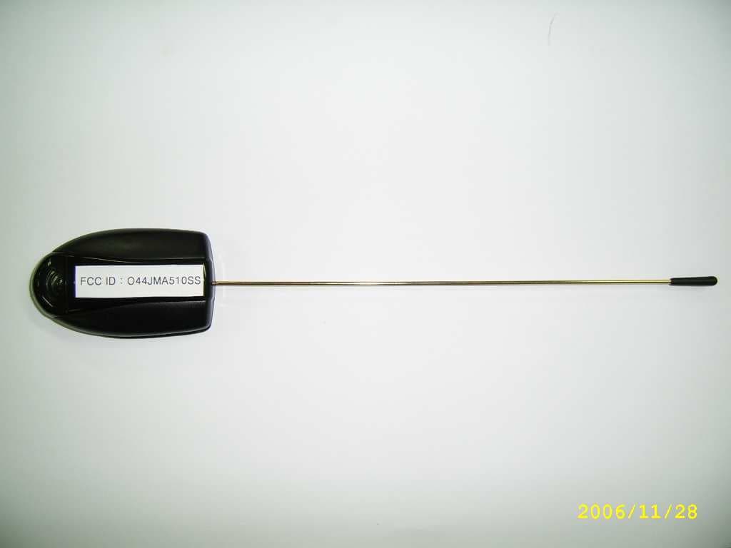
O44JMA510SS
Mar 27, 2007Car alarm
Equipment Class
DSS - Part 15 Spread Spectrum Transmitter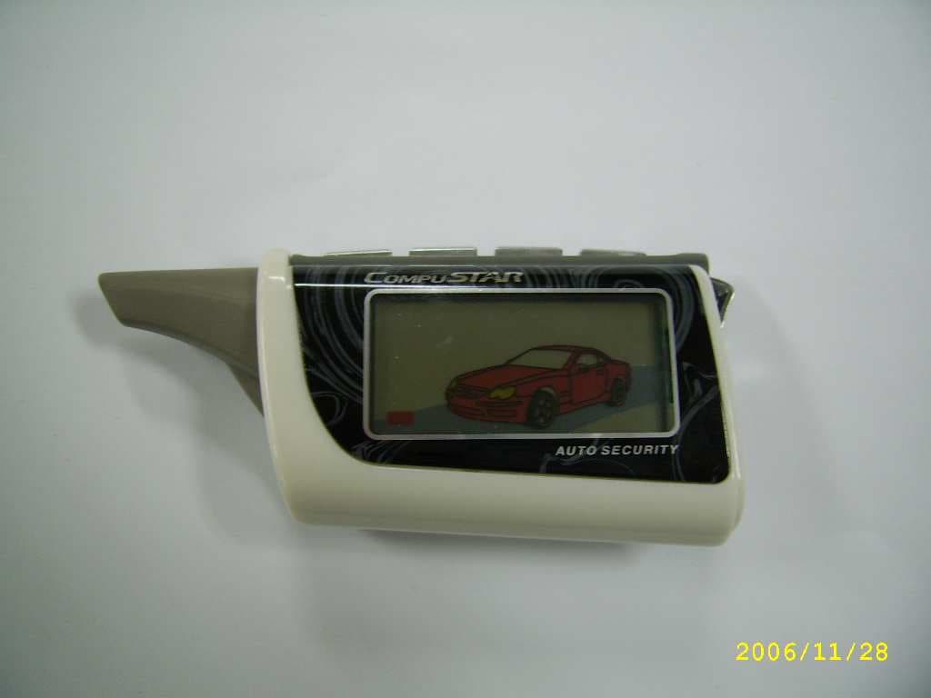
O44JMR600SS
Mar 22, 2007Car Alarm
Equipment Class
DSS - Part 15 Spread Spectrum Transmitter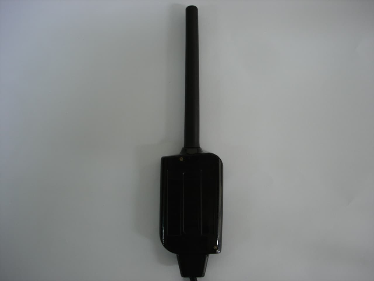
O44JMA580
Sep 11, 2006Two Way Car Alarm System
Equipment Class
DSR - Part 15 Remote Control/Security Device Transceiver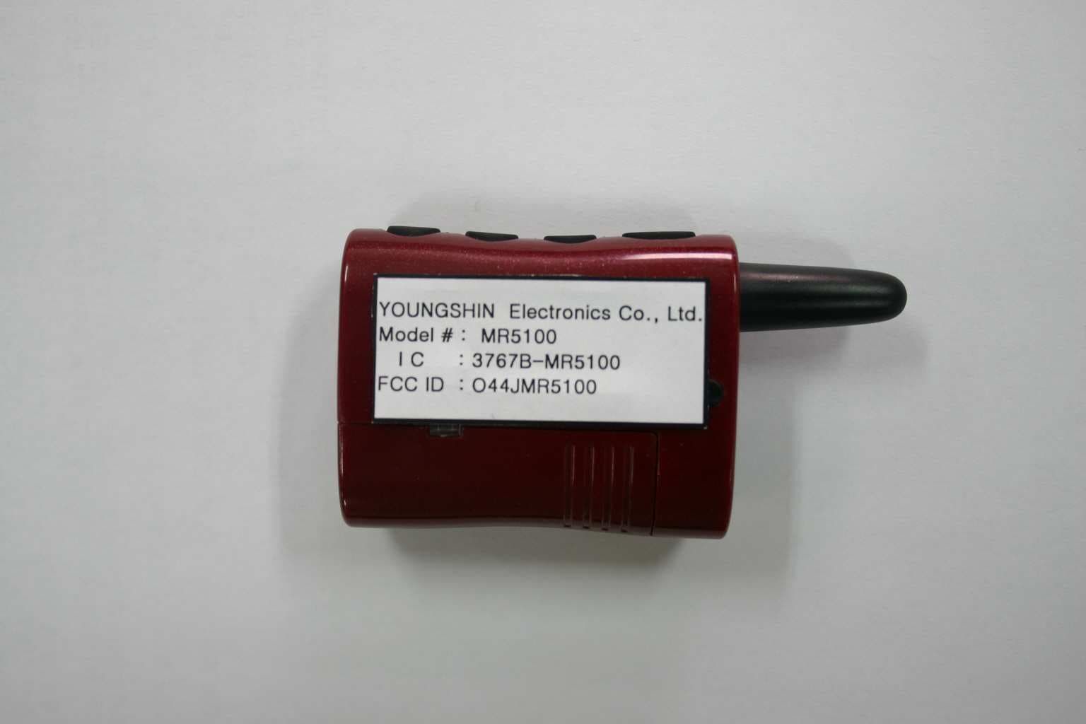
O44JMR5100
Sep 11, 2006Two Way Car Alarm System
Equipment Class
DSR - Part 15 Remote Control/Security Device Transceiver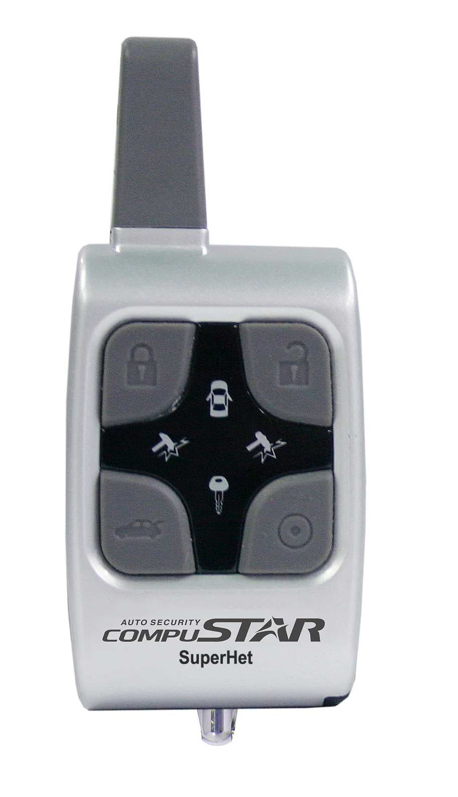
O44JMR540
Sep 11, 2006Two Way Car Alarm System
Equipment Class
DSR - Part 15 Remote Control/Security Device Transceiver