O44JMR540Two Way Car Alarm System
Youngshin Electronics Co., LTD.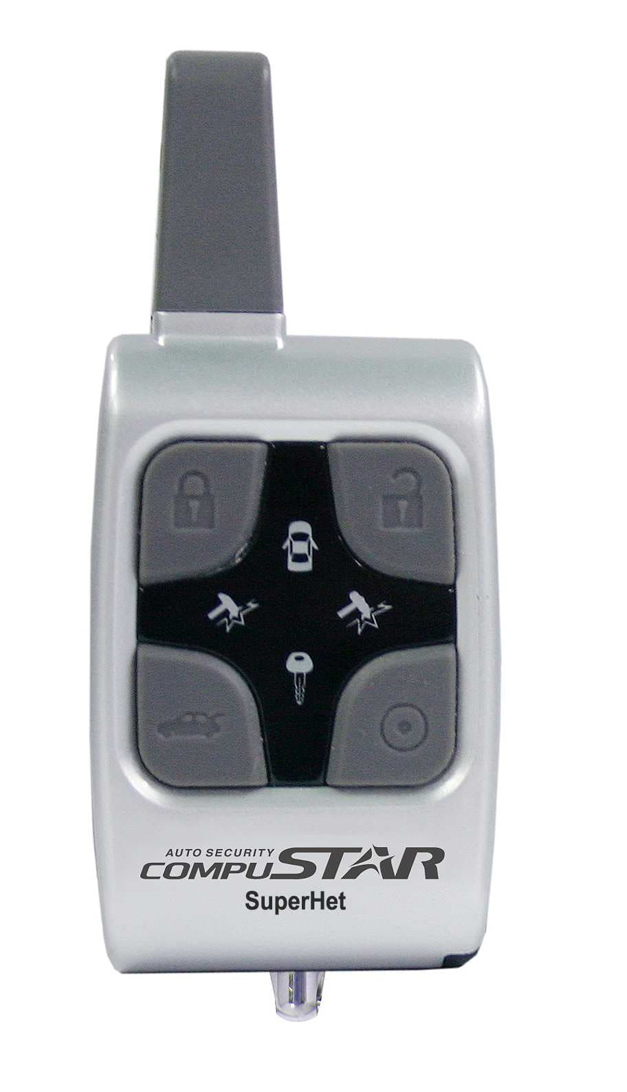
Click to zoom
Application Details
- Equipment Class
- DSR - Part 15 Remote Control/Security Device Transceiver
- Date of Grant
- Sep 11, 2006
- Application Purpose
- Original Equipment
- Date of Application
- Sep 11, 2006
- Equipment Note
- Two Way Car Alarm System
- Frequency Range
- 433.92000000 - 433.92000000
- Country
- South Korea
Documents & Files
Document Text
Text extracted from the exhibit documents filed with the FCC. Open a document above to read the original.
Users Manual
USER’S GUIDE 2WSHR LED FCC ID : O44JMR540This device complies with Part 15 of the FCC Rules. Operation is subject to the following two conditions : (1) This device may not cause harmful interference, and(2) This device must accept any interference received, including interference that maycause undesired operation. Caution : or modifications not expressly approved by the party responsible for compliance could void the user's authority to operate this device. # YoungShin Elc. www.magicar.com USER’S GUIDE 2WSHR LED IC : 3767B-MR540Statement : The term "IC:" before the radio certification number only signifies that Industry Canada technical specifications were met. Caution : The User that modifications to the unit may void the user's authority to operate the unit. # 2 1 Thank you. Thank you for your purchase of a MAGICAR alarm and/or remote-start system. MAGICAR alarms and remote-start systems are the most advanced systems on themarket with amazing features, incomparable ease of use, and breakthrough technologiesnever before used in the automotive environment. Please take time to read andunderstand this owner's manual so that you can fully use and enjoy you new Conpustarsystem. 1. Safety Information 2. Remote-Pager 2WSHR LED3. LED6. Remote-Page LED Functions7. Remote -Page Learn Routine8. Alarm Mode9. Dual Stage Shock Sensor 10.Trunk Release11.Query Function12. Panic Mode13. Valet Mode14. Safety Shutdown Features 15. R.P.S(Remote Paging System)16. Optional Programmable Features Ignition Lock Passive Arming 17. Optional Installation Features Optional Auxiliary 1 & Auxiliary 2 19. Limited Lifetime Consumer Warranty TABLE OF CONTENTS 3445667888999 101010111113 Remote-Pager : 2WSHR/LED LED 4 The model name, 2WSHR LED, stands for 2Way Super Heterodyne Remote. This transmitter that allows you to activate multiple functions by pressing a combination of the 4 the buttons on the unit in order to transmitsignals.The remote-pager comes with a unique LED display that visually tells the youthe security status of your car at all times. There are differing icons that willappear on your LED indicating what your vehicle is currently doing. 0.5 Sec 2 Sec I Lock Panic II III + IV I +II Siren Chips- On/Off Programming Menu 1 + II+III Valet Mode - On/Off Shock Sensor- On/Off AUX2 x Unlock x BUTTON PressFor FUCTION LED ICON Safety Information 3 Please take these safety precautions under the following conditions: 1. Servicing the vehicle When servicing (i.e. changing the oil, washing your car) your automobile, theMAGICAR system should be in Valet Mode. There is a safety shutdown switch under the hood that deactivates the remote starter function if the hood is open.However, if the switch has been damaged or the switch has been installedimproperly, the vehicle may start when the button is pressed for 2 seconds even if the hood is open. 2. Loaning your vehicle to othersWhenever you loan your vehicle to an individual who is not familiar withMAGICAR , please put the vehicle in Valet mode. This will prevent the vehicle loaner from accidentally activating the MAGICAR auto-security system. 3. For manual transmission vehiclesIf the MAGICAR 2WSHR LED is installed in a manual transmission vehicle, extra precautions are required because the system does not monitor the gear shift. Important! Under normal circumstances, Reservation Mode is cancelled when a door orhatchback opens. Please verify if the opening of any door or hatchback cancelsReservation Mode. If any of the doors or hatchback are not monitored byMAGICAR because of improper installation or a faulty dome light switch, do not use the MAGICAR and take your vehicle to the dealer immediately for repair. Do not set Reservation Mode when the window(s) are open or if there is anyoneinside of the vehicle including animals. AUX1 Trunk Open + I +III + I+IV x Programming Menu 2 Passive Locking-On/Off x + III+IV x Query 0.5 Sec 2 Sec 0.5 Sec 2 Sec 0.5 Sec 2 Sec 0.5 Sec 2 Sec 0.5 Sec 2 Sec 0.5 Sec 2 Sec 0.5 Sec 2 Sec 0.5 Sec 2 Sec The MAGICAR system will allow up to three remotes to be programmed to one vehicle. Please perform the following procedure to add or reprogram additionalremotes. Step1 : Activate Valet/Programming mode by manually turning the ignition on and off five times (between Acc and On) with car key within a 7 second period. The parking lights will flash once with successful completion of this step. Step2 : Within a 7 second period after cycling the ignition for the 5 th time, press the button . The car parking lights will flash once to confirm that the transmitter has been programmed. Continue program the additional remotes.The parking lights will flash two times when the programming mode is expired.You can arm by pressing the button for a 1/2 second. You can disarm by pressing the button for a 1/2 second. Press buttons for a 1/2second to make your car siren mute whenarming or disarming your vehicle. Keep in mind that your car siren will stillactivate for all other modes (i.e. panic, alarm, shock sensor) regardless ofwhether or not your car siren is in mute mode. The car siren will be mute onlywhen arming or disarming your vehicle. In alarm mode, the starter kill function (this maybe an optional feature provided by your installer) is activated. This feature disengages the starter mechanism on your car thatprevents you from starting your car even with a manual key when your vehicle s alarm mode is activated. 6 Alarm Mode Remote-Pager Learn Routine ( + ) 5 It a button is pressed, the LED Icon will be flashed rapidly. Also, if the signalwas sent successfully, the remote will beep and the LED icon will flash. If the signal fails, the remote will beep rapidly.Query( + 2 Sec) : When This function is activated, if any of the doors are still open, the Icon will be shown on the remote transmitter Query( + 2 Sec) : If the engine is still running, icon will be shown on the remote. Remote-Pager LED Functions Theft Paging Operation DISPLAY LED ICON DoorTrunkHood ShockSensor …
Text truncated - open the document above for the full version.
Cover Letter(s)
YoungShin Electonics Co.,LTD Date: 26th of July, 2006 Compliance Certification Services Certification Division 561F Monterey Road Morgan Hill, CA 95037 To whom it may concern: We, the undersigned, hereby authorize Korea Testing Laboratory, to act on our behalf in all manners relating to application for equipment authorization, including signing of all documents relating to these matters. Any and all acts carried out by Korea Testing Laboratory, on our behalf shall have the same effect as acts of our own. We, the undersigned, hereby certify that we are not subject to a denial of federal benefits, that includes FCC benefits, pursuant to Section 5301 of the Anti-Drug Abuse Act of 1988, 21 U.S.C. 853(a). In authorizing Korea Testing Laboratory as our agent, we still recognize that we are responsible to: a) comply with the relevant provisions of the certification program; b) make all necessary arrangements for the conduct of the evaluation, including provision for examining documentation and access to all areas, records (including internal audit reports) and personnel for the purposes of evaluation (e.g. testing, inspection, assessment, surveillance, reassessment) and resolution of complaints; c) make claims regarding certification only in respect of the scope for which certification has been granted; d) do not use our product certification in such a manner as to bring the Certification Division into disrepute and not make any statement regarding our product certification which the Certification Division may consider misleading or unauthorized; e) upon suspension or cancellation of certification, discontinue use of all advertising matter that contains any reference thereto and return any certification documents as required by the Certification Division; f) use certification only to indicate the products are certified as being in conformity with specified standards; g) endeavor to ensure that no certificate or report nor any part thereof is used in a misleading manner; h) ensure that any reference to our product certification in communication media such as documents, brochures or advertising, complies with the requirements of the Certification Division; i) keep a record of all complaints made known to the us relating to the product’s compliance with requirements of the relevant standard and to make these records available to the Certification Division when requested; j) take appropriate action with respect to such complaints and any deficiencies found in products or services that affect compliance with the requirements for certification; k) document the actions taken. This authorization is valid until further written notice from the applicant. Sincerely Yours, (Lim Hee Sup/ Research Engineer) (YoungShin Electronics Co.,LTD) REMARK: 1. This authorization letter will be sent along with your application when filing with the Certification Division. 2. Please follow the format and type it on company letterhead and send original to us.
Cover Letter(s)
YoungShin Electonics Co.,LTD C-7F, Bupyung Woolim Lion’s Vally 425, Cheongcheon-dong, Bupyeong-gu, Inchen, Korea(403-030) E-MAIL : [email protected] Federal Communications Commission 7435 Oakland Mills Road Columbia, MD 21046 Gentlemen: This letter is to comply with Section pertaining to confidential material YoungShin Electonics Co.,LTD would like the following documents regarding this submission for FCC ID : O44JMR540 : to be kept confidential. 1. Block Diagram 2. Schematic Diagram The above material contains trade secrets or technical data, which would customarily be guarded from competitors. We do not want these documents to be accessible to the general public. Sincerely, Date 26th of July , 2006 By Byung Hoon Title : Assistant Research Engineer ============================================================
Operational Description
O44J O44JO44J O44JMR540 MR540MR540 MR540 Circuit Descriptions. Circuit Descriptions. Circuit Descriptions. Circuit Descriptions. (Block1,2,3,4,5,6,14 is Logic part and another block is RF part) Block1 : The Battery supply the power of 1.5volts to the DC/DC step-up. Block2 : This is the 3volts DC/DC step-up circuit by U1,D1,L1,TC2,TC3 Block3 : The Buttons of this product. When Being pressed this remote starts to work. Block4 : This is the micro-controller U1(Micro-controller) reads the button and make the radio transmission circuits work. Block5 : This is the external oscillator. XT1 supply the clock to the U1. Block6 : This is the radio power control circuit by U1. U1 make radio frequency circuit (B8) enable by Block6. Block7 : This is the basic oscillation circuit to radiate the radio frequency. (Oscillator 433.92MHz by SAW2) And by switching (between 0V and 3V) at L13 the frequency modulation is done. Block8 : The basic frequency 433.92MHz of Block8 will be amplified at this by Q3. Besides 433.92MHz will be removed by filter (L9,C34,C35) Block9 : Besides 433.92MHz will be removed by filter (L11,C1,C2). Block10 : This is the Low Noise Amplify and SAW filter circuit by Q1,L4,C6,SAW1. Block 11 : This is the First local Frequency oscillator(423.22MHz) circuit by XT1,C16,C17,L5 Block 12 : This is the internal First mixer (10.7MHz) circuit by C9,CF1,U1. Block 13 : This is the internal ASK/FSK switch circuit by U1 Block 14 : This is the reception power control circuit by U1
Operational Description
Transmission Data Format Leading_A BIT0 BIT1 End Data Format 1Word Data Format Content - 1-Word Data Time Length : 64msec ~ 74msec - At One time press button to transmit data of 8-word - 8-Word Data Time Length : 512msec ~592msec E n d P u l se --- --- 10Bit0 Leading_A Total 35BIT Leading_A - - - - - 9msce 55msec ~ 65msec 64msec ~ 74msec 740usc 1480 / 1480us 1110/1110usc 740/740usc
Test Report
KTL Korea Testing Laboratory Page 1 of 15 TEST REPORT This test report only responds to the tested sample and shall not be reproduced except in full without written approval of the Korea Testing Laboratory. Tested and reported by Reviewed by Sung-Kyu Cho, Engineer Seok-Jin Kim , Telecommunication Team Manager KOREA TESTING LABORATORY FG101-01-02-00 222-13, Guro-Dong Guro-Gu Seoul Korea 152-053 http://www.ktl.re.kr Ref. Report No. 06-1341-026-01 Name and address of the applicant Youngshin Electronic Co., Ltd. C-7F, Bupyung Woolim Lion’s Vally 425, Cheongcheon- dong, Bupyeong-gu, Inchen, Korea Standard / Test regulation FCC Part 15, Subpart C IC RSS-210 Test result Pass Incoming date : August 01, 2006 Test item(s) ; Security/Remote Control Transmitter (Car Alarm System) Model/type ref. ; MR540 Manufacturer ; Youngshin Electronic Co., Ltd. Additional information ; -Required Authorization : Certification -FCC ID. : O44JMR540 -IC ID. : 3767B-MR540 Test date : August 16, 2006 Issue date : August 25, 2006 Ref. Report No. 06 - 1341 - 026 - 01 Page 2 of 15 Korea Testing Laboratory Telecommunication Team 222-13, Guro3-dong, Guro-gu, Seoul Korea 152-848 TABLE OF CONTENTS I. GENERAL INFORMATION 3 1. Grantee’s Name and Mailing Address 2. Manufacturer's Name and Mailing Address 3. Equipment Descriptions 4. Rules and Regulations 5. Measuring Procedure 6. Place of Measurement 7. Date of Measurement II. GENERAL REQUIREMENTS OF THE EUT 4 1. Labeling Requirement (FCC section 15.19 & IC RSS-Gen 7.1.5) 2. Information to User (FCC sections 15.21) 3. Special Accessories (FCC section 15.27) 4. Compliant Conditions (FCC section 15.231 & IC RSS-210) 5. Statement of Conformity III. STATEMENT OF CONFORMITY 6 IV. RADIATED EMISSION MEASUREMENT (FCC section 15.231& IC RSS-210) 7 1. Test Procedure 2. Photograph of the test configuration 3. Sample Calculation 4. Measurement Data V. OCCUPIED BANDWIDTH MEASUREMENT (FCC section 15.231 & IC RSS-210 A1.1.3) 14 VI. TEST EQUIPMENTS USED FOR MEASUREMENT 15 Ref. Report No. 06 - 1341 - 026 - 01 Page 3 of 15 Korea Testing Laboratory Telecommunication Team 222-13, Guro3-dong, Guro-gu, Seoul Korea 152-848 I. GENERAL INFORMATION 1. Grantee’s Name and : Youngshin Electronic Co., Ltd. Mailing Address C-7F, Bupyung Woolim Lion’s Vally 425, Cheongcheon-dong, Bupyeong-gu, Inchen, Korea 2. Manufacturer's Name and : Youngshin Electronic Co., Ltd. Mailing Address C-7F, Bupyung Woolim Lion’s Vally 425, Cheongcheon-dong, Bupyeong-gu, Inchen, Korea 3. Equipment Descriptions 3.1 Operating Frequency : 433.92 MHz 3.2 Type of Emission : Pulse Coded Signal 3.3 Power Supply : DC 1.5 V (Battery) 4. Rules and Regulations : FCC Part 15, Subpart C & IC RSS-RSS-210 5. Measuring Procedure : ANSI C63.4-2003 6. Place of Measurement : Absorber-lined Room (KTL) 7. Date of Measurement 7.1 Conducted Emission : Not Applicable 7.2 Radiated Emission : August 16, 2006 Ref. Report No. 06 - 1341 - 026 - 01 Page 4 of 15 Korea Testing Laboratory Telecommunication Team 222-13, Guro3-dong, Guro-gu, Seoul Korea 152-848 II. GENERAL REQUIREMENTS OF THE EUT 1. Labeling Requirement (FCC section 15.19 & IC RSS-Gen section 7.1.5) This device complies with Part 15 of the FCC Rules and with RSS-210 of the Industry Canada rules. Operation is subject to the following two conditions: (1) this device may not cause harmful interface, and (2) this device must accept any interference received, including interference that may cause undesired operation. 1.2 Location of Label : User’s Guide Manual 1.3 How Applied : Printed 2. Information to User (Section 15.21) The following or similar statements were provided in the manual for user instruction. Please refer page 1 of the attached manual for details. CAUTION : Any changes or modifications in construction of this device which are not expressly approved by the party responsible for compliance could void the user's authority to operate the equipment. 3. Special Accessories (Section 15.27) 3.1 Were the special Accessories provided? [ ] yes, [ x ] no 3.2 If yes, details for the special accessories are as follows : 3.3 If yes, were the appropriate instructions provided on the first page of the text concerned with the installation of the device? [ ] yes, [ ] no 3.4 Are these accessories provided of the type which can be readily obtained from multiple retail outlets ? [ ] yes, [ ] no And therefore does the manual specify what additional components or accessories are required to used in order to comply with the Rules? [ ] yes, [ ] no 4. Compliant Conditions (FCC Section 15.231 & IC RSS-210 section A.1) 4.1 Was the EUT used for continuous transmissions, voice or video, and the radio control of toys ? [ ] yes, [ x ] no Ref. Report No. 06 - 1341 - 026 - 01 Page 5 of 15 Korea Testing Laboratory Telecommunication Team 222-13, Guro3-dong, Guro-gu, Seoul Korea 152-848 4.2 Was the EUT manually operated ? [ x ] yes, [ ] no If yes, did the EUT employ a switch that would automatically deactivate the transmitter within not more than 5 seconds of being released ? [ x ] yes, [ ] no 4.3 Was the EUT automatically activated ? [ ] yes, [ x ] no If yes, did the EUT cease transmission within 5 seconds after deactivation ? [ ] yes, [ ] no 4.4 Was the EUT used for periodic transmissions at regular predetermined intervals ? [ ] yes, [ x ] no Ref. Report No. 06 - 1341 - 026 - 01 Page 6 of 15 Korea Testing Laboratory Telecommunication Team 222-13, Guro3-dong, Guro-gu, Seoul Korea 152-848 III. STATEMENT OF CONFORMITY The JMR540 has been found to conform with the following FCC part 15 & IC RSS-210 as detailed below. RSS-210 47 CFR Part # Comments A1.1.1 15.231 (a) Product complies with 15.231 (b) A1.1.2 15.231(b) Product complies with 15.231 (b) A1.1.3 15.231 (c) FCC : 20dB bandwidth of the emission is less than 0.25% of the center Frequency. IC : 99% bandwidth of the emission is less than 0.25% of the center Frequency. Ref. Report No. 06 - 1341 - 026 - 01 Page 7 of 15 Korea Testing Laboratory Telecommunication Team 222-13, G…
Text truncated - open the document above for the full version.
Contact Information
Applicant
Young II Chang(President)
Test Firm
Korea Testing LaboratoryJeong-Min Kim
Technical Specifications
| # | Rule Parts | Frequency Range | Power Output |
|---|---|---|---|
| 1 | 15.231 | 433.92 MHz - 433.92 MHz | - |
Other Applications from Youngshin Electronics Co., LTD.
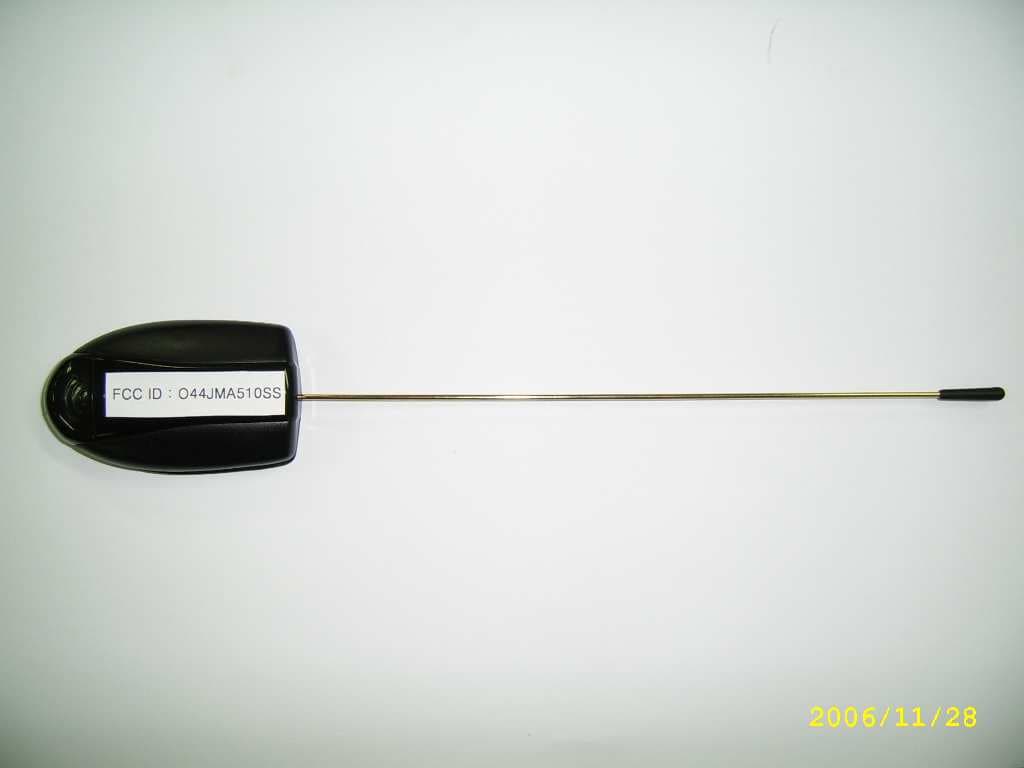
O44JMA510SS
Mar 27, 2007Car alarm
Equipment Class
DSS - Part 15 Spread Spectrum Transmitter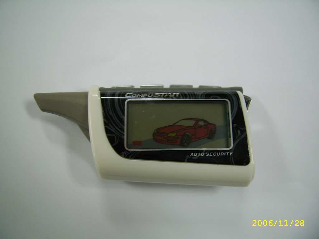
O44JMR600SS
Mar 22, 2007Car Alarm
Equipment Class
DSS - Part 15 Spread Spectrum Transmitter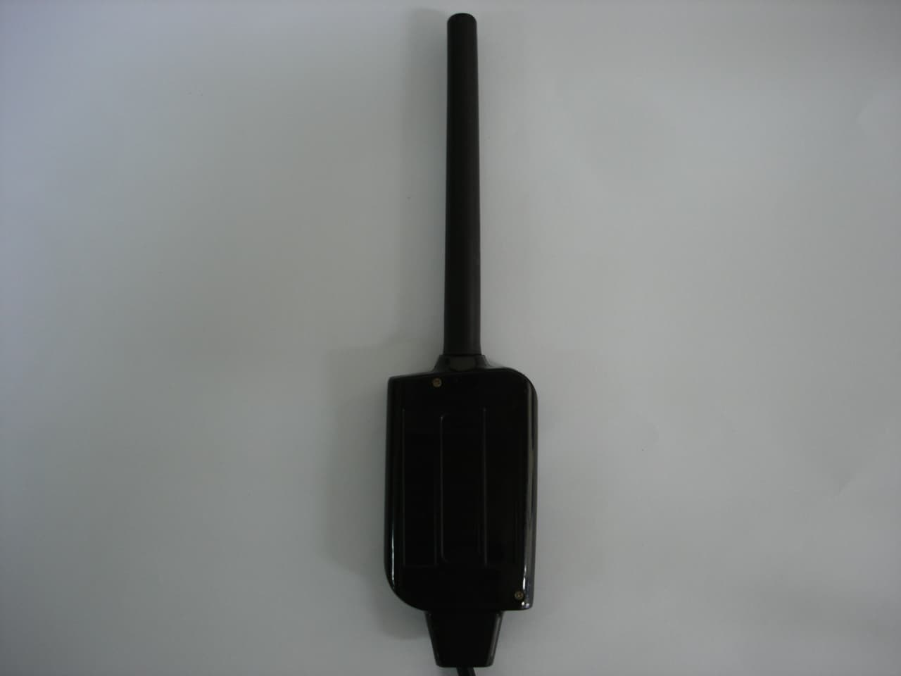
O44JMA580
Sep 11, 2006Two Way Car Alarm System
Equipment Class
DSR - Part 15 Remote Control/Security Device Transceiver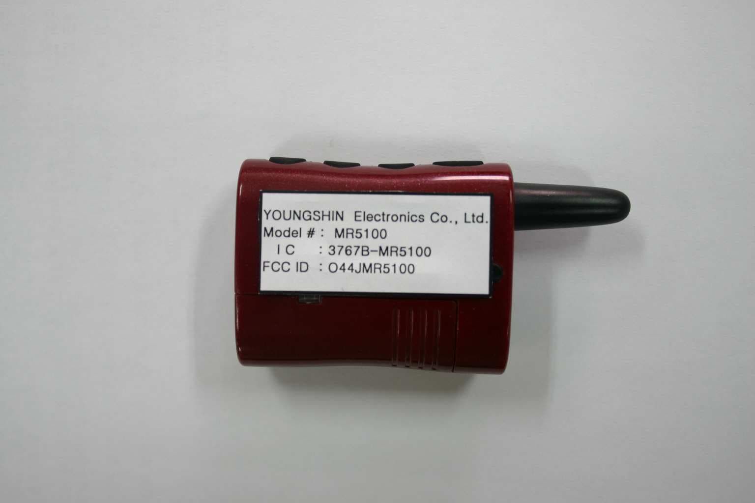
O44JMR5100
Sep 11, 2006Two Way Car Alarm System
Equipment Class
DSR - Part 15 Remote Control/Security Device Transceiver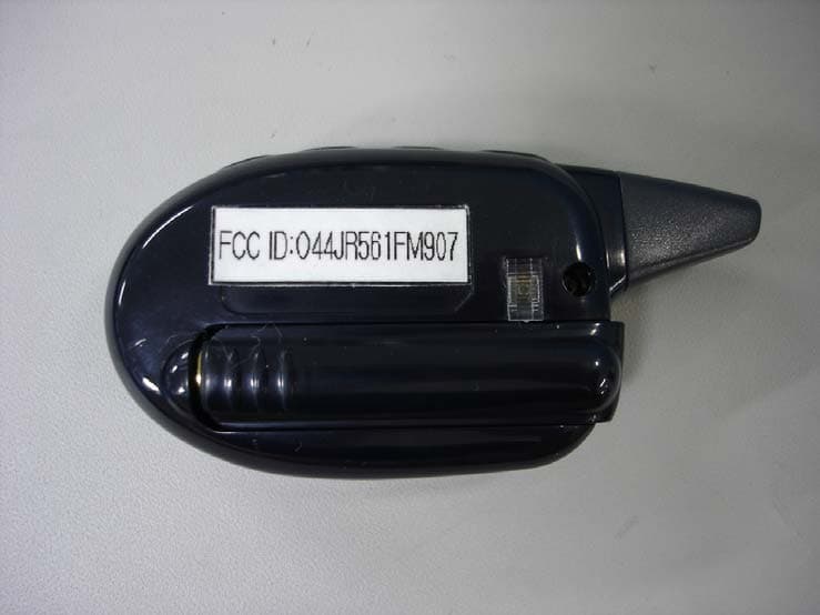
O44JR561FM907
Jul 12, 2006Two Way Car Alarm System
Equipment Class
DSR - Part 15 Remote Control/Security Device Transceiver