O44J2WAMANTCar Alarm System
Youngshin Electronics Co., LTD.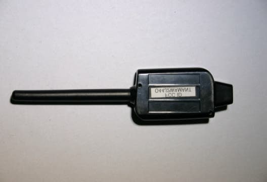
Click to zoom
Application Details
- Equipment Class
- DSR - Part 15 Remote Control/Security Device Transceiver
- Date of Grant
- Jan 09, 2005
- Application Purpose
- Original Equipment
- Date of Application
- Jan 09, 2005
- Equipment Note
- Car Alarm System
- Frequency Range
- 433.90000000 - 433.90000000
- Country
- South Korea
Documents & Files
Document Text
Text extracted from the exhibit documents filed with the FCC. Open a document above to read the original.
Users Manual
Young Shin Electronics, Inc. USER'S GUIDE USER'S GUIDE Young Shin Electronics,Inc. 2WAMANT This device complies with Part 15 of the FCC Rules. Operation is subject to the following two conditions : (1) This device may not cause harmful interference, and (2) This device must accept any interference received, including interference that may cause undesired operation. CAUTION : Changes or modifications not expressly approved by the party responsible for compliance could void the user s authority to operate this device. FCC ID : O44J2WAMANT Page 2Page 3 TABLE OF CONTENTS Wiring Diagram Notes for Wire Connection Switch and Jumper Setting Installation of Antennas Option Programming for Four Button Remotes for FM or SS Units Installation of AM Antennas Option Programming with Programming Button for AM Units Option Programming for Six Button Remotes Programming Menu Options Diagnosing Problems with Auto-Start Page 4 Page 6 Page 12 Page 12 Page 13 Page 14 Page 14 Page 16 Page 16 Page 19 Wiring Diagram Page 4Page 5 Orangehis is the Rearm wire. It provides you with a ( - ) pulse when armed, after remote start, and then again one second after remote start shuts down. As of August 2004, this wire’s output duration has been increased by 1.0 second. This has been done to provide the Dome Light Factory Rearm feature currently offered in the CM3000 controller module. Some vehicles require the door to be open while the door is locked for the factory security system to arm. Connecting this wire to the dome light circuit Page 7 Pin #2 : Red/ BlackThis wire is a (-) 2 nd Starter 200mA output. Normally the only vehicle this would be used on Nissan’s and older Ford’s. You may connect this wire to the purple pigtail of the additional relay on CN #1. This will result in a (+) trigger output for the 2 nd starter on the blue wire of the same relay. Pin #3 : Violet This wire is the (-) Negative when armed out.It will provide a (-) output anytime the unit is armed or remote started. This wire is pre-wired into the starter-kill. This wire could be used for adding a window roll-up. Pin #4 : Black This is the (-)Status Out wire (Ground when running). It provides you with a (-) 200mA output as soon as the remote start is activated. This is the wire you would connect to a Transponder Module or maybe a VATS module. Page 6 Pin #5 : Blue This wire will power (+)2 nd Starter, (+) 2 nd Accessory or (+) 2 nd Ignition depending on the jumper selection at JM1. Pin #6 :Yellow This wire is the (+) Starter Output. Pin #7: Green/ RedThis wire is used to power the (+) Ignition. This wire is also an input for the Young Shin Electronics,Inc. used to monitor the status of the vehicle and for programming. Pin #8 : Black This wire needs to be connected to a chassis (-)Ground. It is very important to make sure you have a good ground or the unit will not function correctly. Pin #1 : RedThis wire is used as the (+)Constant Powerinput for the unit. This wire must be connected for the unit to function correctly. Pin #2 :Green/ WhiteThis wire is the (+)Positive Parkinglight output. Connect this wire directly to the (+) trigger wire generally off the parking light switch or found at or behind the fuse box. Pin #3 :Red/ WhiteThis wire is used as the (+)Constant Power input for Starter and 2 nd Ignition. Pin #4 :White This wire is used to power the (+)Accessory, which activates the blower motor for the heater or A/C. Pin #1 :Green/ WhiteThis is the low voltage (-) Parking light output 200mA. Some newer vehicles require a (-) parking light output instead of the standard (+) output (reference connector #1) such as the new Jeeps and even some Fords. Pin #5 : Page 8Page 9 Pin #7 : White This is the (-) 250mA horn honk output wire. Pin #7 : Brown /BlackThis is the trigger input for a (-) glow plug wire. Pin #8 : Brown /WhiteThis is the trigger input for a (+) glow plug wire. Pin #9 : Yellow/ Black This wire serves as the Tachometer input or the Alternator input. Either way you use it, it is for engine sensing. This wire tells the Young Shin Electronics,Inc. when to quit cranking the starter of the vehicle. There are a couple of ways to find the correct voltage for either type of sensing. Please review the following tips on the next page. 1.You will need an Auto Ranging Digital Meter to test for the correct tach. 2.Most tach wires are located at the (-) side of the ignition coil. In some cases you may have to go to the ECU or Coil pack. 3.The Voltage will read (AC), so you will need to set you meter accordingly. 4. With the vehicle off the voltage should read 0.00 AC. 5. Start the vehicle and at this time the voltage should fluctuate between 1 and 8 volts AC. 6. Connect the tachometer wire to the yellow/black. 7. Make sure that the Dipswitch #1 is set to the On position. 8. While the vehicle is running press the small black button on the side of the brain, Parking Light will flash once if you have the correct Tach wire. 9. If the cars parking lights flash 3 times, there is a problem with the tachometer learning. Wait for 2 seconds and the cause for the error will be indicated by the number of times the parking lights flash. 10. Diagnosing Tach Learning Error Pin #4 : Violet/ BlackThis wire is the (-) trigger input,which may be connected to a trunk pin or trunk trigger as a buyer option. Pin #5 : Red/White This wire is the(-) trigger input for the door trigger. You would connect this to the trigger that shows (-) when the door is opened. Pin #6 : Red This wire is the (+) input for the door trigger. You would connect this to the trigger that shows (+) when the door is opened. Pin #1 : Light Blue This needs to be connected to theparking brake. This wire requires a (-) input to activate. This wire serves two functions: 1. To engage Reservation Mode for manual transmissions, reference the users or install guide. 2. To activate the Turbo Timer , reference the users or install guide. Pin #2 : Gray/ BlackThis is the (-) shutdown for the Hood Trigger. This wire …
Text truncated - open the document above for the full version.
Block Diagram
– –
Cover Letter(s)
1 Helen Zhao Subject:FW: Youngshin Electronics Co., Ltd., FCC ID: O44J2WAMANT, Assessment NO.: AN05T4457, Notice#1 IDLabel_2WAMANT .jpg Manual_O44J2WAM ANT.pdf SidePhoto_O44J2W AMANT.jpg From: jmkim Sent: Monday, January 10, 2005 2:15 AM To: Helen Zhao Subject: Re: Youngshin Electronics Co., Ltd., FCC ID: O44J2WAMANT, Assessment NO.: AN05T4457, Notice#1 Dear Helen; Thank you for your cooperation. > -----Original Message----- > From: Compliance Certification Services [mailto:[email protected]] > Sent: Wednesday, January 05, 2005 4:21 PM > To: Helen Zhao > Subject: Youngshin Electronics Co., Ltd., FCC ID: O44J2WAMANT, > Assessment NO.: AN05T4457, Notice#1 > > > Question #1: Based upon FCC2.925(a)(1) "The FCC Identifier shall be preceded by the term FCC ID in capital letters on a single line." Please revise the FCC ID label format accordingly. > > Question #2: The device shown on the first page of the user manual is totally different from the one in the External Photos exhibit. Please explain. Please provide additional external photos(side). > > Question #3: The user manual is talking about 2WAMR, (FCC ID: O44J2WAMR, Assessment No: AN05T4456). Please resubmit a user manual for 2WAMANT. > > Best Regards, > Helen Zhao > > The items indicated above must be submitted before processing can continue on the above referenced application. Failure to provide the requested information within 30 days of the original e-mail date may result in application dismissal and forfeiture of the filing fee. Also, please note that partial responses increase processing time and should not be submitted. Any questions about the content of this correspondence should be directed to the e-mail address listed below the name of the sender. > > > >
External Photos
[External Photos]
Internal Photos
[Internal Photos]
Test Report
KTL KTL Korea Testing Laboratory Page 1 of 14 Korea Testing Laboratory Page 1 of 14 TEST REPORTTEST REPORT Ref. Report No. 04-1341-032-01 Name and address of the applicant YoungShin Electronic Co., Ltd. 102-701, Bucheon Techno-park 364 Smajeong-dong, Ojeong-gu, Bucheon-si, Gyeonggi-do, 421-740 Korea Standard / Test regulation FCC Part 15, Subpart C Test result Pass Incoming date : November 15, 2004 Test item(s) ; Remote Control/Security Device Transceiver (Two Way Car Alarm System) Model/type ref. ; 2WAMANT Manufacturer ; Youngshin Electronic Co., Ltd. Additional information ; -Required Authorization : Certification -FCC ID. : O44J2WAMANT -Note : Test report(Verification) of Receiver portion of this unit is issued on Ref. Report No. 04-341-032-02. Test date : December 27, 2004 Issue date : January 04, 2005 This test report only responds to the tested sample and shall not be reproduced except in full without written approval of the Korea Testing Laboratory. Tested and reported by Reviewed by Jeong-Min Kim, Senior Engineer Won-Seo Cho , Telecommunication Team Manager KOREA TESTING LABORATORY FG101-01-02-00 222-13, Guro-Dong Guro-Gu Seoul Korea 152-053 http://www.ktl.re.kr Ref. Report No. 04 - 1341 – 032 - 01 Page 2 of 14 Korea Testing Laboratory Telecommunication Team 222-13, Guro3-dong, Guro-gu, Seoul Korea 152-848 TABLE OF CONTENTS I. GENERAL INFORMATION 3 1. Grantee’s Name and Mailing Address 2. Manufacturer's Name and Mailing Address 3. Equipment Descriptions 4. Rules and Regulations 5. Measuring Procedure 6. Place of Measurement 7. Date of Measurement II. GENERAL REQUIREMENTS OF THE EUT 4 1. Labeling Requirement (Section 15.19) 2. Information to User (Sections 15.21) 3. Special Accessories (Section 15.27) 4. Compliant Conditions (Section 15.231) III. RADIATED EMISSION MEASUREMENT (Section 15.231) 6 1. Test Procedure 2. Photograph of the test configuration 3. Sample Calculation 4. Measurement Data IV. OCCUPIED BANDWIDTH MEASUREMENT (Section 15.231) 13 V. TEST EQUIPMENTS USED FOR MEASUREMENT 14 Ref. Report No. 04 - 1341 – 032 - 01 Page 3 of 14 Korea Testing Laboratory Telecommunication Team 222-13, Guro3-dong, Guro-gu, Seoul Korea 152-848 I. GENERAL INFORMATION 1. Grantee’s Name and : YoungShin Electronics Co., Ltd. Mailing Address 102-701, Bucheon Techno-park, 364, Samjeong-dong, Ojeong-gu, Bucheon-si, Kyungki-Do, 421-740 Korea 2. Manufacturer's Name and : YoungShin Electronics Co., Ltd. Mailing Address 102-701, Bucheon Techno-park, 364, Samjeong-dong, Ojeong-gu, Bucheon-si, Kyungki-Do, 421-740 Korea 3. Equipment Descriptions 3.1 Operating Frequency : 433.92 MHz 3.2 Type of Emission : Pulse Code Signal 3.3 Power Supply : DC 12 V (Car Battery) 4. Rules and Regulations : FCC Part 15, Subpart C 5. Measuring Procedure : ANSI C63.4-2001 6. Place of Measurement : Absorber-lined Room (KTL) 7. Date of Measurement 7.1 Conducted Emission : Not Applicable 7.2 Radiated Emission : December 27, 2004 Ref. Report No. 04 - 1341 – 032 - 01 Page 4 of 14 Korea Testing Laboratory Telecommunication Team 222-13, Guro3-dong, Guro-gu, Seoul Korea 152-848 II. GENERAL REQUIREMENTS OF THE EUT 1. Labeling Requirement (Section 15.19) This device complies with Part 15 of the FCC Rules. Operation is subject to the following two conditions: (1) this device may not cause harmful interface, and (2) this device must accept any interference received, including interference that may cause undesired operation. 1.1 Location of Label : User’s Guide Manual 1.2 How Applied : Printed 2. Information to User (Section 15.21) The following or similar statements were provided in the manual for user instruction. Please refer page 1 of the attached manual for details. CAUTION : Any changes or modifications in construction of this device which are not expressly approved by the party responsible for compliance could void the user's authority to operate the equipment. 3. Special Accessories (Section 15.27) 3.1 Were the special Accessories provided? [ ] yes, [ x ] no 3.2 If yes, details for the special accessories are as follows : 3.3 If yes, were the appropriate instructions provided on the first page of the text concerned with the installation of the device? [ ] yes, [ ] no 3.4 Are these accessories provided of the type which can be readily obtained from multiple retail outlets ? [ ] yes, [ ] no And therefore does the manual specify what additional components or accessories are required to used in order to comply with the Rules? [ ] yes, [ ] no Ref. Report No. 04 - 1341 – 032 - 01 Page 5 of 14 Korea Testing Laboratory Telecommunication Team 222-13, Guro3-dong, Guro-gu, Seoul Korea 152-848 4. Compliant Conditions (Section 15.231) 4.1 Was the EUT used for continuous transmissions, such as voice or video, and data transmission ? [ ] yes, [ x ] no 4.2 Was the EUT manually operated ? [ x ] yes, [ ] no If yes, did the EUT employ a switch that would automatically deactivate the transmitter within not more than 5 seconds of being released ? [ x ] yes, [ ] no 4.3 Was the EUT automatically activated ? [ ] yes, [ x ] no If yes, did the EUT cease transmission within 5 seconds after deactivation ? [ ] yes, [ ] no 4.4 Was the EUT used for periodic transmissions at regular predetermined intervals ? [ ] yes, [ x ] no Ref. Report No. 04 - 1341 – 032 - 01 Page 6 of 14 Korea Testing Laboratory Telecommunication Team 222-13, Guro3-dong, Guro-gu, Seoul Korea 152-848 III. RADIATED EMISSION MEASUREMENT (Section 15.231) 1. Test Procedure 1.1 Preliminary Testing for Reference Preliminary testing was performed in a KTL absorber-lined room to determine the emission characteristics of the EUT. The EUT was placed on the wooden table which has dimensions of 0.8 meters in height, 1 meter in length and 1.5 meters in width. Receiving antenna (Biconi-Log antenna : 30 to 1000 MHz or Horn Antenna : 1 to 18 GHz) was placed at the distance of 1 meter from the EUT. An attempt was made to maximize the emission level with the various configurations of the EUT. Emission levels f…
Text truncated - open the document above for the full version.
Test Setup Photos
[Test Photo]
Contact Information
Applicant
Young II Chang(President)
Test Firm
Korea Testing LaboratoryJeong-Min Kim
Technical Specifications
| # | Rule Parts | Frequency Range | Power Output |
|---|---|---|---|
| 1 | 15.231 | 433.9 MHz - 433.9 MHz | - |
Other Applications from Youngshin Electronics Co., LTD.
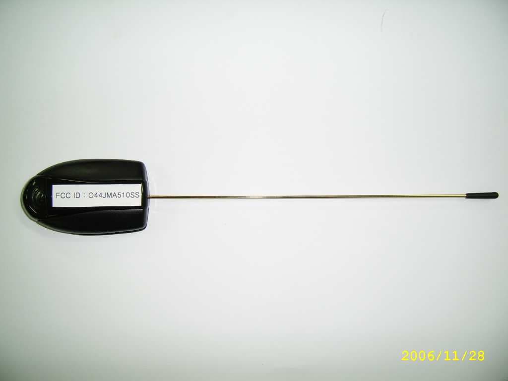
O44JMA510SS
Mar 27, 2007Car alarm
Equipment Class
DSS - Part 15 Spread Spectrum Transmitter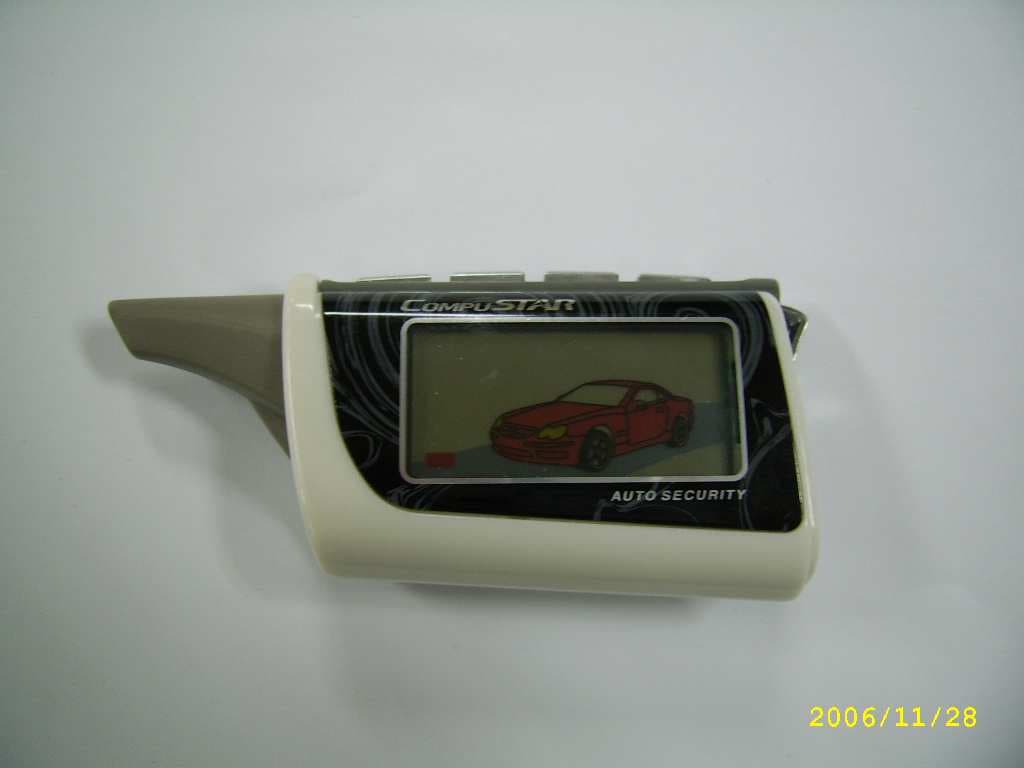
O44JMR600SS
Mar 22, 2007Car Alarm
Equipment Class
DSS - Part 15 Spread Spectrum Transmitter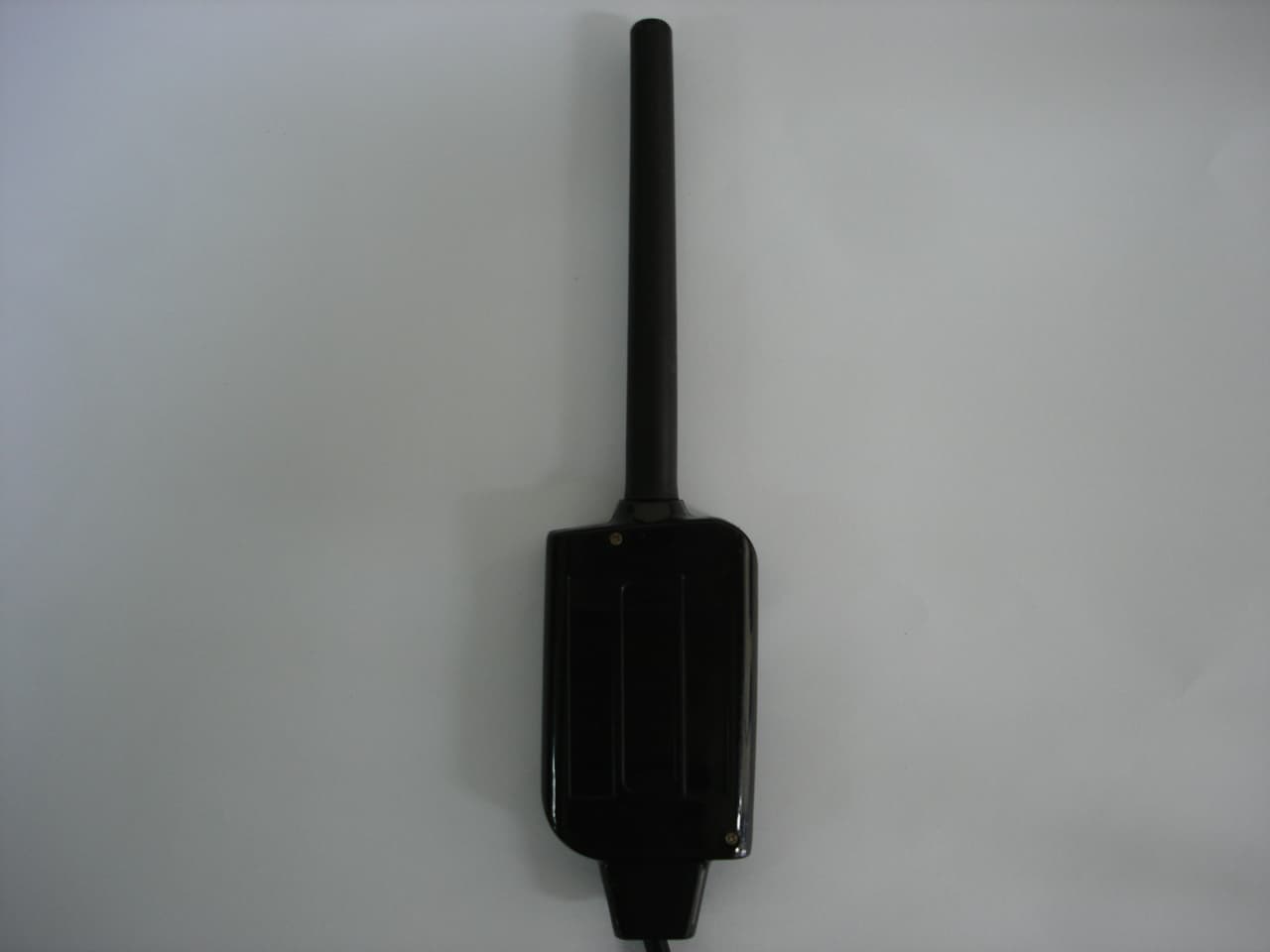
O44JMA580
Sep 11, 2006Two Way Car Alarm System
Equipment Class
DSR - Part 15 Remote Control/Security Device Transceiver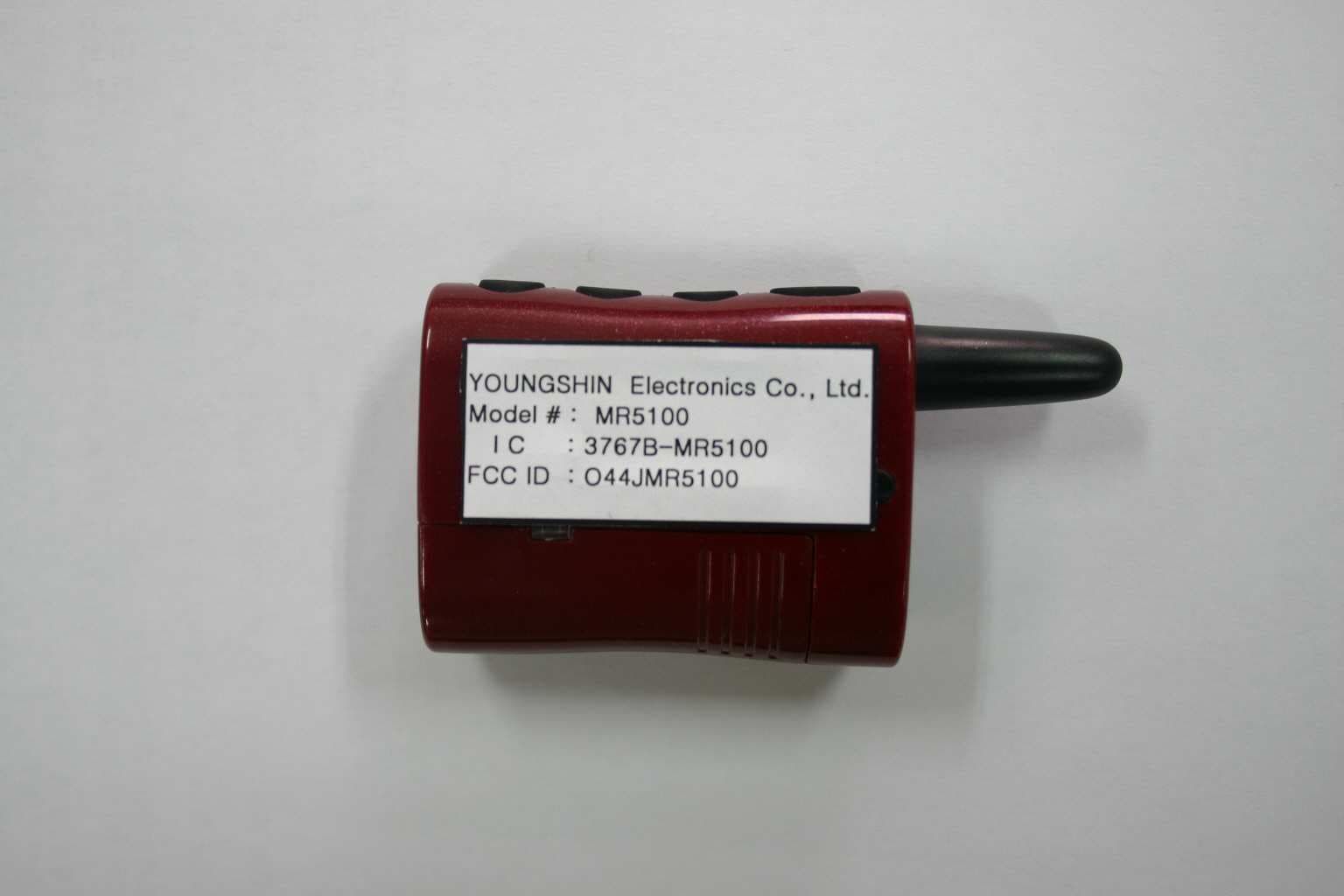
O44JMR5100
Sep 11, 2006Two Way Car Alarm System
Equipment Class
DSR - Part 15 Remote Control/Security Device Transceiver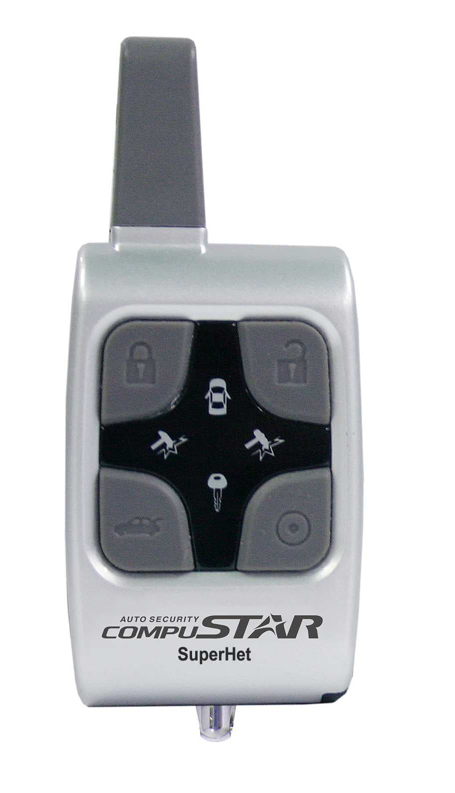
O44JMR540
Sep 11, 2006Two Way Car Alarm System
Equipment Class
DSR - Part 15 Remote Control/Security Device Transceiver