O5VRB715AMarine Radar RA41C
Koden Electronics Co., Ltd
Click to zoom
Application Details
- Equipment Class
- MRD - Marine Radar
- Date of Grant
- Dec 11, 2000
- Application Purpose
- Original Equipment
- Date of Application
- Jul 29, 2000
- Equipment Note
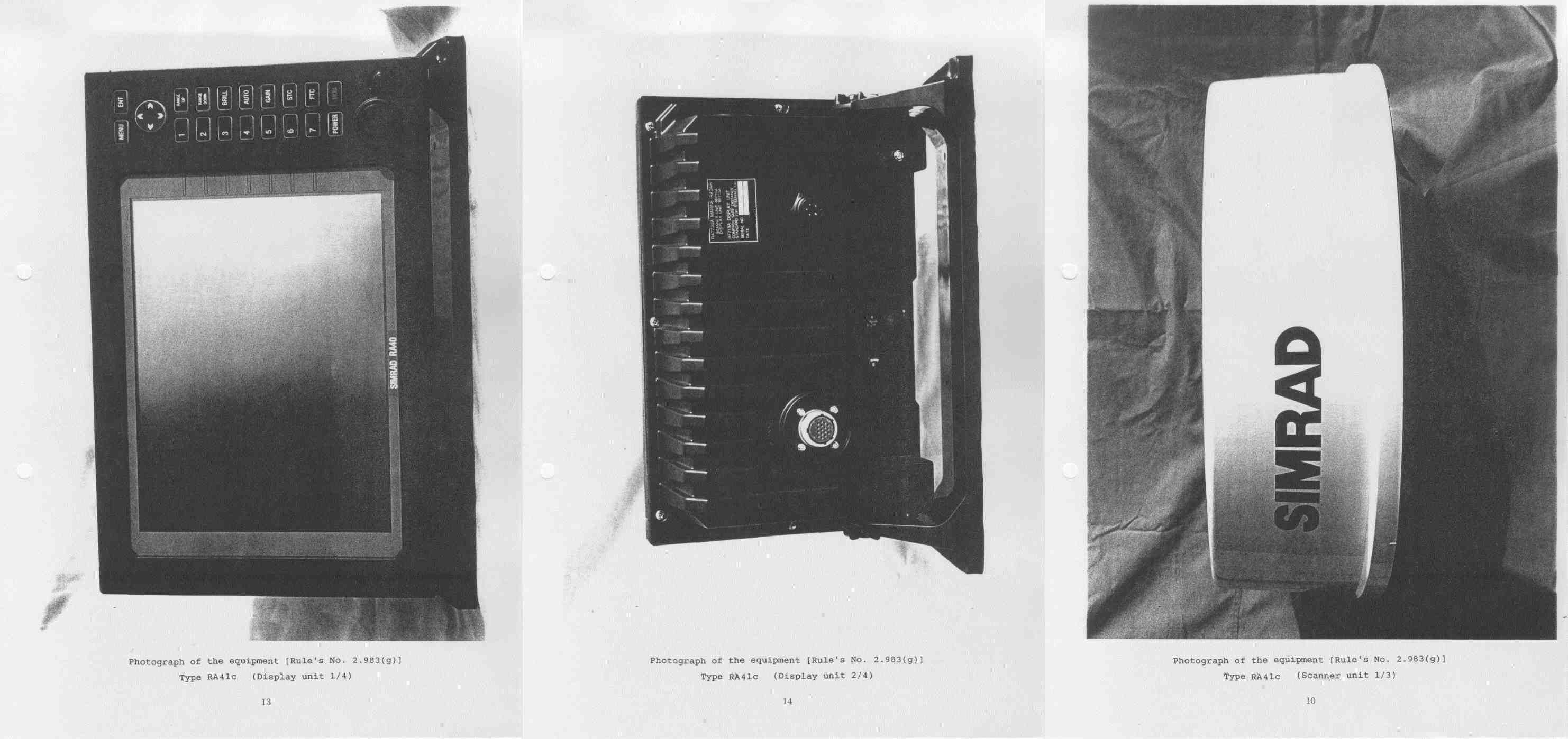
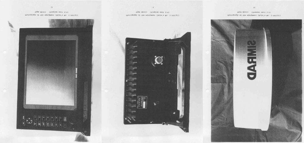
- Marine Radar RA41C
- Frequency Range
- 9300.00000000 - 9500.00000000
- Company
- Koden Electronics Co., Ltd
- Country
- Japan
Documents & Files
Document Text
Text extracted from the exhibit documents filed with the FCC. Open a document above to read the original.
Users Manual
RA40C/RA41C/RA42C Marine Radar Instruction Manual 1st Edition • Read this manual before using the equipment. Kthil
Users Manual
Index A Adjustment Distance ............................... 75 Angle.................................... 75 Tuning ................................. 76 Antenna height ..................... 77 Automatic gain...................... 78 Automatic STC...................... 78 ALL PPI Screen .............................. 64 ALL PPI/PPI Screen ........................ 65 B Bearing scale ................................. 26 Brightness ..................................... 29 Brightness of Panel ............... 29 Buzzer........................................... 71 C Changing setting (CUSTOM)............ 68 Continual variable range (VAR RNG) 38,50 Course error (XTE) ......................... 28 Cross cursor (+).............................. 26 D Display modes (MODE) ................... 38,52 E EBL ............................................ 35,46 Bearing of EBL (EBL BRG) ..... 71 Echo Menu .................................... 56 F False echoes .................................. 5 FL VRM, FL EBL ............................ 36,47 FTC ............................................ 33,57 G Gain ............................................ 32,56 Guard zone (GZ)............................. 38,53 Guard zone mode (GZ MODE) 73 Guard zone level (GZ LVL)...... 73 H Heading marker ............................. 6 Heading Off (HDG OFF)......... 38,49 Heading blink (HM FLSH) ...... 71 Heading information (HEAD) .. 28 Hold (HOLD) .................................. 73 L Language....................................... 73 M Mark Line ...................................... 51 Menu bar....................................... 45 Man Over Board (MOB)................... 34 MOB Screen .................................. 65 Monitor operation (DISPLAY)........... 73 N Nav (Navigation) Menu.................... 52 Navigation screen........................... 28 North mark (NORTH M) .................. 6,71 O Off-center (OFF-C) ..........................39,54 Option............................................87 P Parallel cursor (///CSR)..................38,49 PPI Screen......................................62 PPI/NAV Screen .............................64 PPI/PPI Screen ...............................63 PPI/SEMI3D Screen........................63 Pulse table (P TABLE)......................71 R Radar interference ..........................6 Radar screen ..................................26,27 Range ............................................31 Range rings (RINGS) .......................38,50 Range ring interval.................50 Reverse screen ...............................42,66 S Semi-3D.........................................43,63 Sleep (SLEEP) .................................54 Speed (SPEED, SPD SET) ................73 ST'BY ............................................29 ST'BY NAV screen...........................71 STC ............................................32,57 Stern marker (STERN M).................71 Stretch (ST) ....................................41,58 Switching the screen (SEL WIN) .......42,65 System check ................................66 T Target (TARGET).............................51 Track (TRACK)................................41,58 Tune ............................................40,57 Tune meter ...................................26 V VAR RNG .......................................38,50 VRM ............................................35,47 Unit of VRM (RM UNIT) ..........71 W Way point (WAYP) ...........................28 Bearing of Way point (WP BRG)... 71 X XTE ............................................28,44 Z Zoom (ZOOM) .................................41,59
Users Manual
i To prevent the risk of personal injury or damage to the equipment, the following safety symbols are used to indicate safety-related information. Insure that you clearly understand the meanings of the symbols BEFORE using the equipment. Symbols Used in Manual This indicates a very dangerous procedure that could result in serious injury or death if not performed properly. This indicates a hazardous procedure that could result in serious injury or death if not performed properly. This indicates a hazardous procedure or danger that could result in light-to-severe injury, or that might damage the equipment, if proper precautions are not taken. Safety Symbols Used on Equipment The following safety symbols are used inside or on the equipment near operation lo- cations to provide information about safety items and operation precautions. Insure that you clearly understand the meanings of the symbols and take the necessary pre- cautions BEFORE using the equipment. This indicates high voltages with a risk of serious electric shock if the part is touched. NEVER touch the part with bare hands, etc. The symbol prohibits the operation show n inside the symbol. (The ex- ample in the left prohibits disassembly.) The symbol indicates that the operation inside the symbol is potentially hazardous. (The example on the left indicates that the plug should be held when disconnecting it from the AC outlet.) This indicates the ground (earth) terminal. If the equipment cannot be grounded via the power cord, connect this terminal to ground. There is a risk of serious electric shock if the equipment is not grounded. RA40C/RA41C/RA42C Marine Radar Instruction Manual 21st Jul. 2000 (1st Edition) Document: E-A40C/41C/42C-2-00 Safety Symbols DANGER ! WARNING ! CAUTION ! ii • DO NOT OPEN T HE CO VER EXCEPT SERVICE PERSO NNEL. YO U MAY G ET AN ELECTR IC SHOCK. • SWITCH OFF SHIPS MAIN AND PULL OFF MOTOR FUSE BEFORE MAINTENANCE. ROTATING ANTENNA MAY HIT YOU. • KEEP OFF DUR ING TRANSMISSIO N. RADIATION LEVEL: 100W/m 2 DISTANCE : 0.8m RADIATION LEVEL: 10W/m 2 DISTANCE : 8m • DO NOT DROP COVER. IT MAY HIT SOMEBODY. • •••••••••••••••••••••• ••••••••••••• • •••••••••••••••••••••••• •••••••• ••••••••••••••••••••••••• • ••••••••••••••• ••••• : 100W/m 2 •• : 0.8m ••••• : 10W/m 2 •• : 8m • •••••••••••••••••• ••••••••••• • DO NOT PAINT T HE RADO ME. PERFORMANCE WILL DOWN. • •••••••••••••••••••• •••••••• WARNING and CAUTION for Scanner Unit and Antenna ; ! There is a risk of receiving electric shock if these parts are to uched by accident. Only qualified perso nnel sho uld remove covers on these parts. " To avoid accidental antenna rotation, turn off ship’s main and pull off out the motor fuse during repair inspect, or maintenance. When repairing or inspecting the scanner unit wear a safety harness and provide a secure platform so that there is no danger of falling even when the vessel lists or when there is an unexpected incident such as an earth quake. # Do not approach the antenna while it is transmitting. In additio n, at inspection never look into the wave guide during trans- mission. $ When remove the scanner cover etc., do not drop it. It may endanger people below. % Do not paint the RADOME. Antenna performance will be do wn. For Safety WARNING / • • CAUTION / • • • • • • • iii • SEE INSTR UCT IO N MANUALS BEFORE CONNECTING POWER. SAFETY INFOR MATIO N IS WR ITTEN IN. • EARTH CO NNECTIO N ESSENTIAL BEFORE CO NNECT ING POWER. YOU MAY GET AN ELECTR IC SHOCK. • DO NOT OPEN T HE COVER EXC EPT SERVICE PERSO NNEL. HIG H VOLTAGE IS INSID E. YOU MAY GET AN ELECTR IC SHOCK. • ••••••••••••• •••••••••••• •••••••••••••• • •••••••••••••• ••••••••• •••••••••••• • ••••••••••••• •••••••••• •••••••••••••• •••••• WARNING for Display Unit ; ! See instructio n manuals before connecting power. Safety information is written i n. " Earth connection essential before connecting supply. There is a risk of serious electric shock if the equipment is not grounded. # There is a risk of receiving electric shock if these parts are to uched by accident. Only qualified perso nnel sho uld remove covers on these parts. WARNING / • • • • • iv Installation Radio laws dictate that this radar may only be installed by properly licensed personnel. Licensing You must obtain a license as prescribed by the Radio Law to operate this unit. To Customers * To use this equipment effectively, the operation and maintenance procedure in this manual must be followed properly. Note that this equipment is only a navigational instrument hav- i ng no w arrant for navigatio n safety. No n-e xec utio n of funda me ntal na vi gatio n req uire- ments such as the ship location check or lookout is not allowed. * If some abnormality occurs in this equipment, immediately turn off the equipment POWER switch and the radar main switch in the power distribution board and notify our mainte- nance section or dealer. * This instrument uses oscillator and LCD backlight. They are easy to be broken. Do not subject the instrument to excessive force or drop it. * The mercury (Hg) is used in LCD backlight. When you discard your radar, it is due to laws or regulations of your nations.
Users Manual
Contents For safety CHAPTER 1 OVERVIEW .................................................................... 1 1.1 Introduction ................................................................................................. 1 1.2 Organization of This Manual ....................................................................... 1 CHAPTER 2 USING RADAR FOR THE FIRST TIME .............................. 2 2.1 What is a radar ? ......................................................................................... 2 2.2 Characteristics of Radar Wave .................................................................... 3 2.3 Terms Specific to Radars ............................................................................. 6 CHAPTER 3 INSTALLATION ............................................................... 10 3.1 Checking Contents of Your Package ........................................................... 10 3.2 Checking Power Supply Voltage .................................................................. 11 3.2.1 Power Supply Requirement.................................................................... 12 3.2.2 Fuse Replacement .................................................................................. 12 3.3 Determining Place of Installation ................................................................ 12 3.3.1 Scanner unit........................................................................................... 12 3.3.2 Display unit ............................................................................................ 12 3.3.3 Shifting away from obstacles ................................................................. 13 3.4 Installing Scanner Unit............................................................................... 14 3.5 Installing Antenna Unit............................................................................... 15 3.6 Installing Display Unit................................................................................. 16 3.7 Connecting Cables ....................................................................................... 17 3.7.0 Interconnecting cable (RA40C Radome scanner)............................................17 3.7.1 Interconnecting cable (RA41C Radome scanner) .................................. 17 3.7.2 Interconnecting cable (RA42C Open scanner) ....................................... 20 3.7.3 Grounding wire....................................................................................... 21 3.7.4 Power supply cable ................................................................................. 22 3.8 Adjustment .................................................................................................. 22 3.9 Connecting External Equipment to Display Unit ....................................... 23 3.10 Countermeasure for Electromagnetic Interference .................................. 23 3.11 When Discarding Your Radar.................................................................... 24 CHAPTER 4 FUNCTIONS AND NAMES ............................................... 25 4.1 Key layout .................................................................................................... 25 4.2 Rear panel.................................................................................................... 26 4.3 Radar screen (Single screen) ....................................................................... 26 4.4 Radar screen (Dual screen) ......................................................................... 27 4.5 Radar screen (All PPI screen) ...................................................................... 27 4.6 Radar screen (All PPI/PPI screen) ............................................................... 28 4.7 Navigation screen ........................................................................................ 28 CHAPTER 5 OPERATION ................................................................... 29 Basic operation of Radar ................................................................................... 29 5.1 Powering On and Off.................................................................................... 29 5.2 Adjusting brilliance of screen and key-backlight........................................ 29 5.3 Basic Operations ......................................................................................... 30 5.3.1 Powering On and Off...............................................................................30 5.3.2 Transmitting ...........................................................................................30 5.3.3 Adjusting brilliance of screen and key-backlight...................................31 5.3.4 Changing Distance Range (RANGE UP, RANGE DOWN) .......................31 5.3.5 Automatic adjustment (AUTO) ...............................................................31 5.3.6 Sensitivity adjustment (GAIN) ................................................................ 32 5.3.7 Removing sea clutter (STC)..................................................................... 32 5.3.8 Removing rain and snow clutter (FTC)................................................... 33 5.3.9 Man Over Board (MOB) ..........................................................................34 5.4 Functions of Soft Keys .................................................................................35 5.4.1 Bearing measurement (EBL1).................................................................35 5.4.2 Bearing measurement (EBL2).................................................................35 5.4.3 Distance measurement (VRM1) ..............................................................35 5.4.4 Distance measurement (VRM2) ..............................................................36 5.4.5 Measuring the angle between two points (FL EBL2) ..............................36 5.4.6 Measuring the distance between two points (FL VRM2) ........................36 5.4.7…
Text truncated - open the document above for the full version.
Users Manual
1 CHAPTER 1 OVERVIEW 1.1 Introduction The RA40C/41C/42C represents a compact, high-performance color marine radar that delivers a peak power output of 2 kW(RA40C) or 4 kW(RA41C/42C) from the an- tenna and uses an 10-inch color liquid crystal display. In addition to a microcomputer, it incorporates a video signal processing LSI and a newly developed LSI chip exclusively designed for radars, thus providing versatile func- tionality and high performance. Features 1. A thin display unit incorporating a liquid crystal display. 2. Easy operation using only a few keys and menu screens. 3. A position of key and its function can be set in position ( Selectable soft func- tion key). 4. Easy operation by the rotary knob. Gain, STC, FTC, EBLs, VRMs etc. can be controlled by the rotary knob. 5. A short and a long range echo can be seen at a time ( Dual range radar). 6. Semi-3D screen display for easy identification of targets in noise. 7. Capable of continuous distance range changes (Continual variable range). 8. Waterproof construction of display allows installation at any desired location. 1.2 Organization of This Manual This manual provides a wide range of information necessary to operate the RA40C/41C/42C radar ranging from the basic knowledge on radars to the methods of operating, installing, and maintaining the radar. The manual also provides rather detailed technical informa- tion on how to adjust video display to obtain clear images. You are requested to read this manual thoroughly from beginning to end in order to understand the various functions of the radar so you can take full advantage of its advanced functions. If you are using a radar for the first time, refer to the basic data on radars in CHAPTER 2. This manual consists of the following chapters: USING RADAR FOR THE FIRST TIME...................... CHAPTER 2 INSTALLATION...................... CHAPTER 3 FUNCTIONS AND NAMES...................... CHAPTER 4 OPERATION...................... CHAPTER 5 INSPECTION AND MAINTENANCE...................... CHAPTER 6 TROUBLESHOOTING ...................... CHAPTER 7 PRODUCT SPECIFICATIONS...................... CHAPTER 8 If you are an experienced user of radars, skip CHAPTER 2 and begin from CHAPTER 3.
Users Manual
2 CHAPTER 2. USING RADAR FOR THE FIRST TIME This chapter describes basic information on radars and explains technical terms used in radar operation for those who is using a radar for the first time. 2.1 What is a radar ? A marine radar is one of the navigation equipment installed on a ship. It emits a radio wave in very high frequency called a microwave from its antenna and receives the reflected radio wave from objects on the sea (e.g., other ships, buoys, and lands). The received radio wave is converted into an electric signal which is displayed on a display screen to indicate the presence of such objects. Although it is very difficult to find other ships or the destina- tion coast with human eyes at night or in thick fog, a radar helps you detect objects on the sea helping you avoid danger when sailing. The antenna turns 360 degrees as it radiates waves, allowing you to grasp ambient conditions around your ship at a glance. The radio wave radiated from the antenna is called a pulse wave and the radar performs transmission and reception alternately. Several hundred to several thousand pulse waves generally are transmitted while the antenna rotates one turn. Antenna There are many types of antennas generally used for a radar. For example, these include a parabolic antenna and a slotted-array antenna. The performance of the antenna determines that of the radar. The dominant factors are the antenna's beam width and side lobe level. The narrower the beam width, the higher the resolution of the angle direction. The lower the side lobe level, the fewer the effect of a false echo. Side lobe A beam in one direction in which the strongest radio wave is radiated from the antenna is called the main lobe and beams in other directions are called "side lobes". The side lobe level refers to the differ- ence in level between the largest side lobe and the main lobe. Buoy Other ship Radar wave Your ship Antenna (Rotating) Radar display Fig.2-1 What is a radar? Beam width Side lobe level Main beam Side lobe Antenna Fig.2-2 Antenna pattern 3 Beam width A beam width is defined as the width of the main lobe at an angle where the radi- ated power is halved as measured from the position from which the strongest radio wave is radiated. 2.2 Characteristics of Radar Wave Radio waves from the radar propagate while bending slightly along the terrestrial sur- face. This characteristic varies dependent on the density of the atmospheric air. The sight distance D of a radar generally is said to be approximately 6% longer than the optical sight distance and is calculated using the equation below : D (NM) = 2.22 ( h1 + h2 ) where,h1= antenna height in meters h2= target height in meters Fig.2-3 Radar wave Targets difficult to display on screen The intensity of the reflected wave from a target depends on the distance, height, and size of the target, as well as its material and shape. Targets constructed with FRP, wood, or other low-reflectance materials or those that have a small incident angle are difficult to display on a screen. Therefore, FRP and wooden ships, sandy beaches, and sandy or muddy shallows all are difficult to catch and require attention when monitoring on the screen. Especially, coast lines on the radar image appear to be pre- sent more apart from the ship than they are actually located. Therefore, it is important not to misinterpret the available data. Shadow zones of radar Radar waves are characteristic in that they propagate straight ahead. Therefore, if the ship's smokestack or mast is located near the antenna or there is a tall ship or mountain at the side of the ship, such an object generates a shadow behind it. In this Apparent coastline Actual(invisible) coastline Invisible Visible 3 1 HU Fig.2-4 Targets difficult to display on screen h1h2 Line of sight Radar Radio Wave Earth 4 case, some objects produce a complete shadow and some produce a partial shadow. In an extreme case, the shadow of an object may extend to a position far away and can- not be displayed on the screen at all. Since these shadows can be discovered when in- stalling an antenna, the problem can be avoided by changing the place of antenna in- stallation to minimize the shadow. Targets in shadow zones are difficult to display on the screen. False echoes A false echo of an actually nonexistent object may sometimes appear on the screen when sailing. The following explains the cause of each of such phenomena. A. Ghost echoes It sometimes happens that one large object near the ship appears at two different bearings. One is the actual echo and other is a ghost echo generated as the wave is re- reflected from the ship's own smokestack or mast. The former appears at the correct distance and bearing on the screen and the latter appears behind the smokestack or mast. This type of false echo is also generated by re-reflection of waves from bridges and quay walls other than the ship itself. B. Multiple echoes If there is a large vertical reflecting plane near the ship as in the case when your ship passes alongside a large ship, the wave is repeatedly reflected back and forth between your ship and the other object. For this reason, two to four images appear on the screen at equal intervals in the same bearing. A false echo that is generated by such multiple reflections is called multiple echoes. In this case, an image appearing at the nearest position is the real echo. Multiple echoes disappear as the ship moves away from the reflecting object or its bearing changes. Therefore, it is not difficult to determine the correct image. Target Direct reflection path Secondary reflection path Mast etc. Real echo Ghost echo Direction of ghost echo 3 1 HU Fig.2-5 False echoes of radar (Ghost echoes) 5 C. False echoes caused by side lobe The radiant beam emitted from an antenna contains side lobes in directions other than that of the main beam. Since the side lobe level is low, it in no way affects distant targets. However, if there is a strong reflectin…
Text truncated - open the document above for the full version.
Users Manual
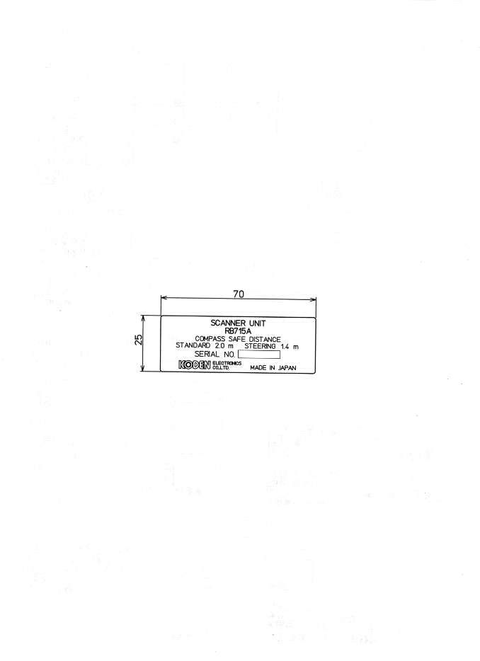
10 CHAPTER 3. INSTALLATION This chapter describes procedures for installing the RA40C/41C/42C radar in your ship and precautions to be observed during installation. Follow the procedure below to in- stall the radar. 3.1 Checking Contents of Your Package First, unpack your package and see if all of the following items are included. RA40C RA41C RA42C ItemQ'TY Q'TY Q'TY Display unit 1 (RF719A) 1 (RF719A) 1 (RF719A) Scanner unit1 (RB714A) 1 (RB715A) 1 (RB716A) Display cover1 1 1 Fuse2 2 4 Interconnecting cable1 (10 m) 1 (10 m) 1 (10 m) Power supply cable1 (2 m) 1 (2 m) 1 (2 m) M10 hexagonal bolt4 sets 4 sets 0 M12 hexagonal bolt0 0 4 sets Carbon brush0 0 2 Checking contents of your package Checking power supply voltage Determining place of installation Installing scanner unit Installing display unit Connecting cables Adjustment Connecting external equipment When discarding Your radar 11 The package contains a 10m interconnecting cable as an accessory. Longer cable is also available as an option as listed in Tab.3-1. Tab.3-1 Optional Interconnecting Cable In addition to the above components included with your package, the following items are also required. Please prepare them separately. ItemQTYRemarks Tapping screw or M5 bolt and nut6 setsTo install display unit Grounding wire1Earth line for display unit Grounding wire and crimp terminal1 setEarth line for scanner unit 3.2 Checking Power Supply Voltage 3.2.1 Power Supply Requirements For the RA40C/41C/42C radar to be operated normally, the power supply (battery) detailed in Tab.3-2 is required. Note also that if the battery is discharged, its voltage may fluctuate greatly, causing the radar to malfunction. When start up the radar system or start transmitting, an additional rush current is required on the power line. Carefully check the power supply system including wiring by using a circuit tester. Tab.3-2 Power Supply Requirements *A.C. power cannot be used 3.2.2 Fuse Replacement For the RA40C/41C/42C radar to be operated safely, proper rating fuses must be used. Tab.3.3 and Tab.3.4 are fuse rating tables for RA40C/41C and RA42C. Check them and replace to the fuse in the package. Tab.3-3 Supply Voltage to Fuse Table for RA40C/41C Tab.3-4 Supply Voltage to Fuse Table for RA42C RA40CRA41CRA42C Cable length Product No. Product No. Product No. 15m242J160680B24Y159099B24Y159169B 20m242J160680C24Y159099C24Y159169C 25m24Y159099D24Y159169D 30m242J160680D Supply voltage used Maximum current Allowable range of voltage DC12V5A10.2-41.6V DC24V2.5A10.2-41.6V Supply voltage used Main FuseMotor Fuse DC12V8A/250V or 125V * (6.3 • x 32mm) T3.15A/250V or 125V * (5 • x 20mm) DC24V8A/250V or 125V (6.3 • x 32mm) T3.15A/250V or 125V (5 • x 20mm) 12 ••• Note: Marked * fuses are in the set as standard. 3.3 Determining Place of Installation 3.3.1 Scanner unit A radar's target detection capacity varies greatly depending on the fitted position of the scanner. An ideal fitting position is a location high above the ship's keel line where there is no obstacle all around the scanner. In an actual ship, such an ideal location is limited by various factors. Therefore, consider the following suggestions when you determine the place to install the scanner: (a) Install scanner at a position as high as possible. The higher the installation position, the longer the radio ranging distance. Install the scanner at a position as high as possible after considering the ship's hull structure and radar maintainability. (b) Install scanner away from smoke-stack and mast If the scanner is installed at the same height as the smoke-stack or mast, radar waves may be blocked, creating shadow zones or generating false echoes. Therefore, do not install the scanner at such a position. (c) Install scanner forward away from obstacle. To avoid creating shadow zones or generating false echoes, install the scan- ner at a position nearer to the ship's bow away from obstacles. When installing the scanner on a mast, position it in front of the mast. (If obstacles cannot be avoided for the ship's structural reasons, refer to "Shifting away from obstacles" described Page 13.) (d) Do not install the scanner near hot or heat-generating items. Do not install the scanner at a position where it may be subjected to smoke or hot air from smokestacks or heat from lamps. (e) Install the scanner away from antennas of other equipment. Install the scanner as much away from the antennas of a direction finder, radio transceiver, etc. as possible. To eliminate the interference, install the scanner away from the antenna of radio transceivers. (f) Make the cable length as short as possible. Keep the distance from the scanner to the display unit within the standard cable length of 10 m. If you use longer cable for unavoidable reasons, limit the cable length to a maximum of 30 m for RA40C and 100 m for RA41C/42C. 3.3.2 Display unit The display unit can be installed on desktop, wall surface, or ceiling. Determine the place to install the display unit that is convenient for navigation and radar operation after considering the following suggestions: Supply voltage used Main FuseMotor Fuse DC12V10A/250V or 125V (6.3 • x 32mm) 5A/250V or 125V (5 • x 20mm) DC24V 8A/250V or 125V * (6.3 • x 32mm) T3.15A/250V or 125V * (5 • x 20mm) ! CAUTION 13 (a) A place where you can see the ship's bow when you raise your face from the radar screen. (b) A place where there is no direct sun-light to avoid display temperature up. (c) A place where there is good ventilation and minimum vibration. (d) A place where the display unit is apart more than the minimum safe dis- tance from a magnet compass as listed in Tab.3-5 below. Tab.3-5 Minimum Safe Distance from Magnetic Compass 3.3.3 Shifting away from obstacles ! !! ! Shifting from keel line By shifting the scanner position from the keel line to the starboard side of the ship, it is possible to move shadow zones to the port side which makes it possible to keep clear vision in the bow direction. The…
Text truncated - open the document above for the full version.
Users Manual
29 CHAPTER 5. OPERATION Basic operation of radar The RA40C/41C/42C radar has several fixed-function keys on the front panel. These functions can be controlled by simply pressing the key. Also, special functions can be customized to soft-keys by user-setting. The followings explain the operation of each keys. 5.1 Powering On and Off (1) Powering On Press the "POWER" key. Buzzer sounds "pi" and starts the radar system. Screen brilliance is set to the level that of the radar system has been powered off. (2) Powering off Keep pressing the "POWER" key more than 3 seconds, then the radar system will power off. 5.2 Adjusting brilliance of screen and key-backlight (1) Press the "BRILL" key. (Bar and figure indicating brilliance, and figure indicating key- backlight appear on the screen.) (2) Adjust each items with the control knob. Items can be selected by up-down cursor…
Text truncated - open the document above for the full version.
Contact Information
Applicant
Kazuhiro Moriguchi(General Manager, Engineering Department)
Technical Contact
Koden Electronics Co., LtdHiroyuki Iida
[email protected]+81-554-20-5868
1500 Northwest 1st Street, Suite 1-M · Yamanashi, Florida · United States
Non-Technical Contact
Simrad Inc.Brian G Vlad
954-922-7700
Technical Specifications
| # | Rule Parts | Frequency Range | Power Output | Emission |
|---|---|---|---|---|
| 1 | 80 | 9.30 GHz - 9.50 GHz | 4000 W | 54M4P0N |
Other Applications from Koden Electronics Co., Ltd
O5VRB715L
Oct 21, 2003MODEL RA41C RADAR
Equipment Class
MRD - Marine Radar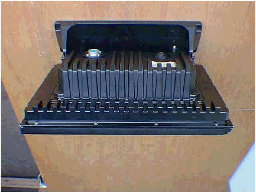
O5VRB719A
Nov 24, 2002Marine Radar RA55
Equipment Class
MRD - Marine Radar
O5VRB717A
Oct 02, 2001Marine Radar RA53
Equipment Class
MRD - Marine Radar
O5VRB718A
Oct 02, 2001Marine Radar RA54
Equipment Class
MRD - Marine Radar
O5VRB714A
Dec 11, 2000Marine Radar RA40C
Equipment Class
MRD - Marine Radar