O5VRB715LMODEL RA41C RADAR
Koden Electronics Co., Ltd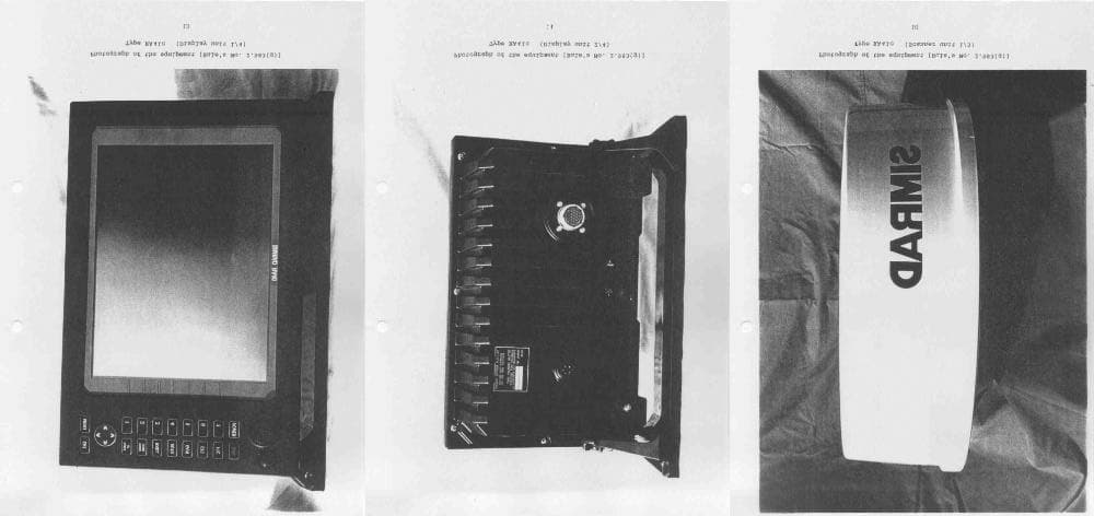
Click to zoom
Application Details
- Equipment Class
- MRD - Marine Radar
- Date of Grant
- Oct 21, 2003
- Application Purpose
- Original Equipment
- Date of Application
- Oct 21, 2003
- Equipment Note
- MODEL RA41C RADAR
- Frequency Range
- 9300.00000000 - 9500.00000000
- Company
- Koden Electronics Co., Ltd
- Country
- Japan
Documents & Files
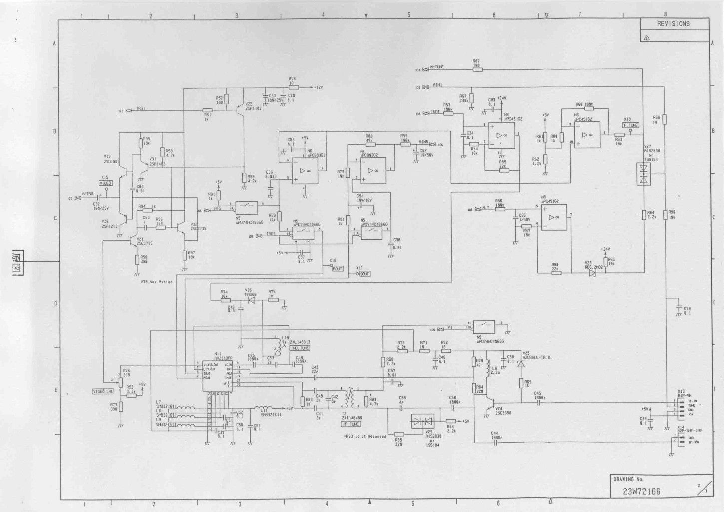
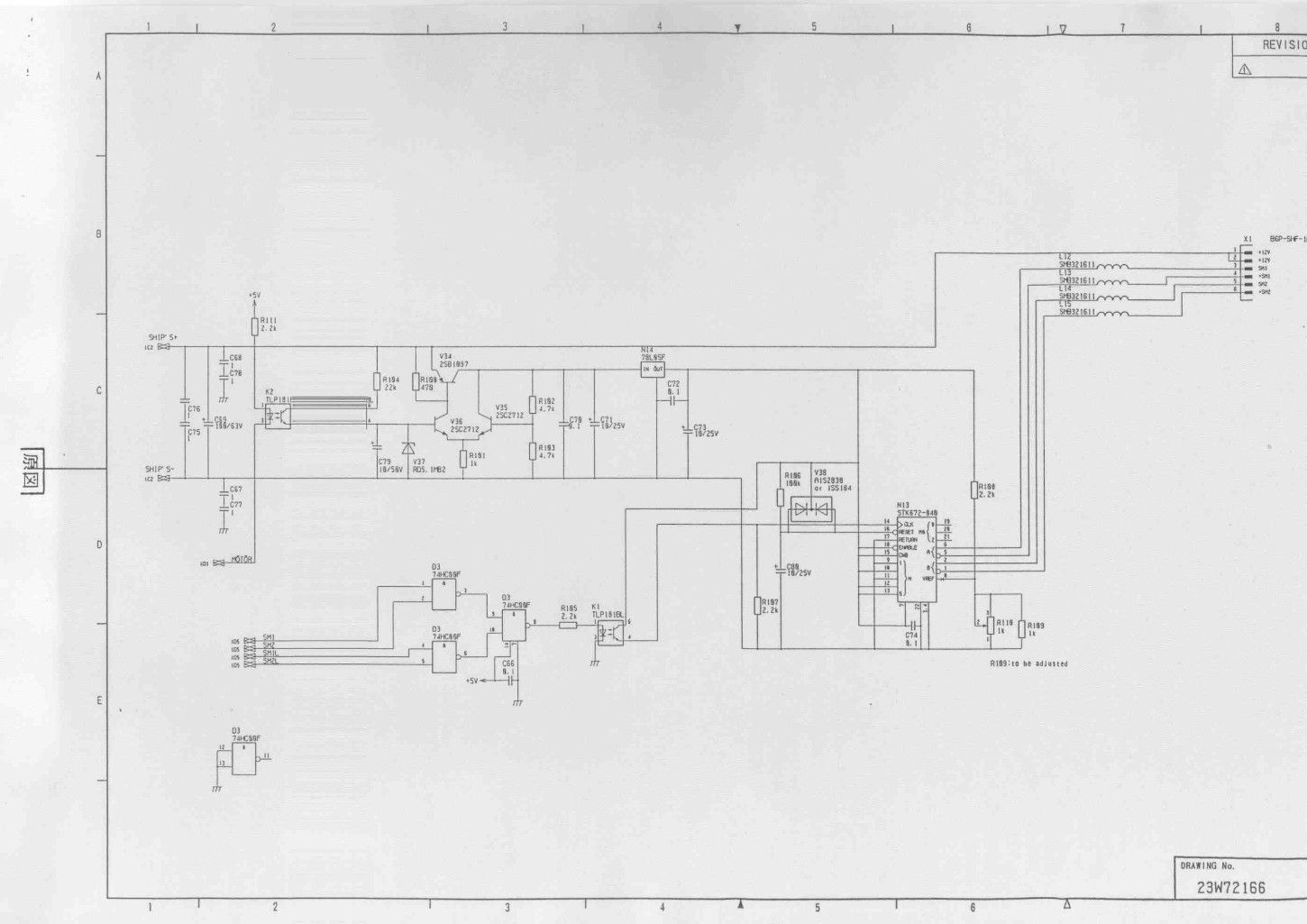
Document Text
Text extracted from the exhibit documents filed with the FCC. Open a document above to read the original.
Users Manual
RA40C/RA41C/RA42C Marine Radar Instruction Manual 1st Edition • Read this manual before using the equipment. Kthil Index A Adjustment Distance ............................... 75 Angle.................................... 75 Tuning ................................. 76 Antenna height ..................... 77 Automatic gain...................... 78 Automatic STC...................... 78 ALL PPI Screen .............................. 64 ALL PPI/PPI Screen ........................ 65 B Bearing scale ................................. 26 Brightness ..................................... 29 Brightness of Panel ............... 29 Buzzer........................................... 71 C Changing setting (CUSTOM)............ 68 Continual variable range (VAR RNG) 38,50 Course error (XTE) ......................... 28 Cross cursor (+).............................. 26 D Display modes (MODE) ................... 38,52 E EBL ............................................ 35,46 Bearing of EBL (EBL BRG) ..... 71 Echo Menu .................................... 56 F False echoes .................................. 5 FL VRM, FL EBL ............................ 36,47 FTC ............................................ 33,57 G Gain ............................................ 32,56 Guard zone (GZ)............................. 38,53 Guard zone mode (GZ MODE) 73 Guard zone level (GZ LVL)...... 73 H Heading marker ............................. 6 Heading Off (HDG OFF)......... 38,49 Heading blink (HM FLSH) ...... 71 Heading information (HEAD) .. 28 Hold (HOLD) .................................. 73 L Language....................................... 73 M Mark Line ...................................... 51 Menu bar....................................... 45 Man Over Board (MOB)................... 34 MOB Screen .................................. 65 Monitor operation (DISPLAY)........... 73 N Nav (Navigation) Menu.................... 52 Navigation screen........................... 28 North mark (NORTH M) .................. 6,71 O Off-center (OFF-C) ..........................39,54 Option............................................87 P Parallel cursor (///CSR)..................38,49 PPI Screen......................................62 PPI/NAV Screen .............................64 PPI/PPI Screen ...............................63 PPI/SEMI3D Screen........................63 Pulse table (P TABLE)......................71 R Radar interference ..........................6 Radar screen ..................................26,27 Range ............................................31 Range rings (RINGS) .......................38,50 Range ring interval.................50 Reverse screen ...............................42,66 S Semi-3D.........................................43,63 Sleep (SLEEP) .................................54 Speed (SPEED, SPD SET) ................73 ST'BY ............................................29 ST'BY NAV screen...........................71 STC ............................................32,57 Stern marker (STERN M).................71 Stretch (ST) ....................................41,58 Switching the screen (SEL WIN) .......42,65 System check ................................66 T Target (TARGET).............................51 Track (TRACK)................................41,58 Tune ............................................40,57 Tune meter ...................................26 V VAR RNG .......................................38,50 VRM ............................................35,47 Unit of VRM (RM UNIT) ..........71 W Way point (WAYP) ...........................28 Bearing of Way point (WP BRG)... 71 X XTE ............................................28,44 Z Zoom (ZOOM) .................................41,59 i To prevent the risk of personal injury or damage to the equipment, the following safety symbols are used to indicate safety-related information. Insure that you clearly understand the meanings of the symbols BEFORE using the equipment. Symbols Used in Manual This indicates a very dangerous procedure that could result in serious injury or death if not performed properly. This indicates a hazardous procedure that could result in serious injury or death if not performed properly. This indicates a hazardous procedure or danger that could result in light-to-severe injury, or that might damage the equipment, if proper precautions are not taken. Safety Symbols Used on Equipment The following safety symbols are used inside or on the equipment near operation lo- cations to provide information about safety items and operation precautions. Insure that you clearly understand the meanings of the symbols and take the necessary pre- cautions BEFORE using the equipment. This indicates high voltages with a risk of serious electric shock if the part is touched. NEVER touch the part with bare hands, etc. The symbol prohibits the operation show n inside the symbol. (The ex- ample in the left prohibits disassembly.) The symbol indicates that the operation inside the symbol is potentially hazardous. (The example on the left indicates that the plug should be held when disconnecting it from the AC outlet.) This indicates the ground (earth) terminal. If the equipment cannot be grounded via the power cord, connect this terminal to ground. There is a risk of serious electric shock if the equipment is not grounded. RA40C/RA41C/RA42C Marine Radar Instruction Manual 21st Jul. 2000 (1st Edition) Document: E-A40C/41C/42C-2-00 Safety Symbols DANGER ! WARNING ! CAUTION ! ii • DO NOT OPEN T HE CO VER EXCEPT SERVICE PERSO NNEL. YO U MAY G ET AN ELECTR IC SHOCK. • SWITCH OFF SHIPS MAIN AND PULL OFF MOTOR FUSE BEFORE MAINTENANCE. ROTATING ANTENNA MAY HIT YOU. • KEEP OFF DUR ING TRANSMISSIO N. RADIATION LEVEL: 100W/m 2 DISTANCE : 0.8m RADIATION LEVEL: 10W/m 2 DISTANCE : 8m • DO NOT DROP COVER. IT MAY HIT SOMEBODY. • •••••••••••••••••••••• ••••••••••••• • •••••••••••••••••••••••• •••••••• ••••••••••••••••••••••••• • ••••••••••••••• ••••• : 100W/m 2 •• : 0.8m •••…
Text truncated - open the document above for the full version.
ID Label/Location Info
Page 1 of 1 10/16/03http://corinth.gothicsoftware.net/exchange/timco-summer/Inbox/SITEX%20Marine%20-%20Job#1293UT3.EML/1_multipart_xF8FF_2_RB715L.JPG...
Operational Description
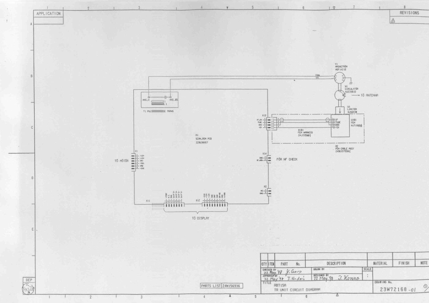
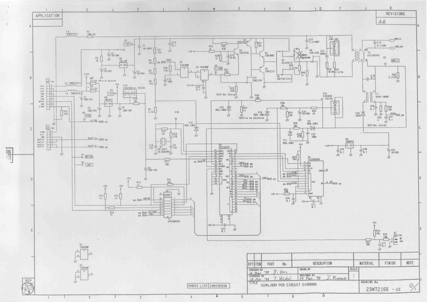
Operational Description MARINE RADAR RA41C 1. A description of all circuitry and devices provided determining and stabilizing frequency. Rule's No. 2.983(d)-(10) 1.1 The oscillating frequency stability of pulsing magnetron depends upon the load characteristics. In this radar, the load of the magnetron consists of a duplexer, a waveguide feeder and an antenna, and the load is matched to the magnetron. The VSWR of the load is better than 1.25 within the specified frequency range. 1.2 Receiver The oscillating frequency stability of FET local oscillator depends upon the supply voltage and ambient temperature. For obtaining the desired frequency stability of oscillator, following means are provided. In addition this radar equips an automatic tuning circuit to coincide the receiver frequency with the transmission frequency. 1.2.1 Temperature compensation High Q strip line of the oscillator circuitry is employed in the Front-End module due to temperature compensation. 1.2.2 Stabilizing the power supply DC voltage supplied to the FET local oscillator is stabilized by the regulator. DC voltage across the varactor diode for tuning is supplied from a D/A converter. The voltage across the D/A converter is made by dividing the regulated 24 volts DC. The regulated voltage is generated by regulator on power supply unit. Therefore stable oscillation can be obtained. 2. A description of any circuits or devices employed for suppression of spurious radiation , for limiting modulation, and for limiting the operating power. Rule's No. 2.983(d)-(11) 2.1 Circuits or devices employed for suppression of spurious 1 radiation. 2.1.1 Suppression of spurious radiation from antenna A duplexer, a waveguide feeder and an antenna perform the narrow band-pass filter and all the spurious signals outside the radar frequency band are suppressed -50dB lower than main radiation level. 2.1.2-1 Line filters The line filters are provided on the ship's power supply line as follows; Line filter L4 and capacitors C1-C4,C18-C19,C68-C69 and C77 on POWER PCB in the display unit. 2.1.2-2 Special interunit connection cable A special 12 cores cable shielded by the metal braid is employed for the interunit connection and the grounding of the braid are made surely at both ends. 2.2 Circuits or devices for limiting the modulation and operating power Transmitting tube, pulsing magnetron, operates with negative going high voltage pulse in the modulator. DC 250 volts as the modulator source generated by the DC-DC converter with voltage regulator(power supply unit) is supplied to the modulator to generate the modulating pulse with constant amplitude. Accordingly, modulation and transmitter power level are maintained constant.
RF Exposure Info
Evaluating Compliance with FCC-Specified Guidelines for Human Exposure to Radio frequency Radiation Radar Type: RA41C FCC ID: O5VRB715A Manufacturer: Koden Electronics Co., Ltd Reference: Sec. 1.1310 Radio frequency radiation exposure limits Table 1--Limits for Maximum Permissible Exposure (MPE) (B) Limits for General Population/Uncontrolled Exposures 1500-100,000MHz 1mW/cm 2 Calculation: (1) Average Output Power (Pav) -1 Pulse duty factor Peak Output Power 4kW (4000W) Repetition Frequency 600Hz Pulse Width 0.8 us (0.0000008s) Average Output Power = 4000(W) x 600(Hz) x 0.0000008(s) Po = 1.92 (W) -2 Mechanical scanning duty factor Horizontal Beam Width 3.9 deg. (Continuously Rotating with 360 deg.) Pav = Po x 3.9(deg.) / 360(deg.) = 1.92 x 3.9 / 360 = 0.0208 (W) (2) Antenna Gain (Ga) 24.1dB ( 257 ) (3) Power Density Limit (Plim) 10 (W) ; 1mW/cm 2 = 10W/m 2 (4) K (Factor of Ground Reflection) 4 Range of Limits (m) = (( Pav x Ga x K )/( 4 x x Plim )) = (( 0.0208 x 257 x 4 )/( 4 x x 10 )) = 0.413 (m) According to above calculation, this radar is comply with " Sec. 1.1310 Radio frequency radiation exposure limits ". 001020 /Hiroyuki Iida/Koden Electronics Co., Ltd
RF Exposure Info
3.3 Determining Place of Installation 3.3.1 Scanner unit A radar's target detection capacity varies greatly depending on the fitted position of the scanner. An ideal fitting position is a location high above the ship's keel line where there is no obstacle all around the scanner. In an actual ship, such an ideal location is limited by various factors. To comply with FCC RF exposure requirements, the radar antenna for this scanner must be installed to provide a separation distance of 50 cm or more from all persons. Therefore, consider the following suggestions when you determine the place to install the scanner: (a) Install scanner at a position as high as possible. The higher the installation position, the longer the radio ranging distance. Install the scanner at a position as high as possible after considering the ship's hull structure and radar maintainability. (b) Install scanner away from smoke-stack and mast If the scanner is installed at the same height as the smoke-stack or mast, radar waves may be blocked, creating shadow zones or generating false echoes. Therefore, do not install the scanner at such a position. (c) Install scanner forward away from obstacle. To avoid creating shadow zones or generating false echoes, install the scanner at a position nearer to the ship's bow away from obstacles. When installing the scanner on a mast, position it in front of the mast. (If obstacles cannot be avoided for the ship's structural reasons, refer to "Shifting away from obstacles" described Page 13.) (d) Do not install the scanner near hot or heat-generating items. Do not install the scanner at a position where it may be subjected to smoke or hot air from smokestacks or heat from lamps. (e) Install the scanner away from antennas of other equipment. Install the scanner as much away from the antennas of a direction finder, radio transceiver, etc. as possible. To eliminate the interference, install the scanner away from the antenna of radio transceivers. 12-1 ! CAUTION (f) Make the cable length as short as possible. Keep the distance from the scanner to the display unit within the standard cable length of 10 m. If you use longer cable for unavoidable reasons, limit the cable length to a maximum of 30 m for RA40C and 100 m for RA41C/42C. 3.3.2 Display unit The display unit can be installed on desktop, wall surface, or ceiling. Determine the place to install the display unit that is convenient for navigation and radar operation after considering the following suggestions: (a) A place where you can see the ship's bow when you raise your face from the radar screen. (b) A place where there is no direct sun-light to avoid display temperature up. (c) A place where there is good ventilation and minimum vibration. (d) A place where the display unit is apart more than the minimum safe distance from a magnet compass as listed in Tab.3-5 below. Tab.3-5 Minimum Safe Distance from Magnetic Compass 12-2 Master compass Steering compass Scanner unit 2.0m 1.4m Display unit 2.0m 1.4m
Test Report
9 Exhibit 2 TEST RESULT Modulation Characteristics (Detected Pulse) (1) Short Pulse Pulse width (-3 dB) = 124 ns Pulse repetition Frequency = 2008 Hz 50 ns/div. 10 Exhibit 2 TEST RESULT Modulation Characteristics (Detected Pulse) (2) Middle Pulse Pulse width (-3 dB) = 244 ns Pulse repetition Frequency = 1473 Hz 50 ns/div. 11 Exhibit 2 TEST RESULT Modulation Characteristics (Detected Pulse) (3) Long Pulse Pulse width (-3 dB) = 773 ns Pulse repetition Frequency = 583 Hz 100 ns/div. 14 Exhibit 3 TEST RESULT Transmission Spectrum of 110 ns × 2000 Hz Center frequency : 9.4179GHz Frequency span : 20.0 MHz/div. Level : 10 dB/div. Resolution band width : 300 kHz/div. Video band width : 1 MHz/div. Sweep time : 200 msec/div. Occupied band width : 54.4 MHz 15 Exhibit 3 TEST RESULT Transmission Spectrum of 250 ns × 1500 Hz Center frequency : 9.4179GHz Frequency span : 10.0 MHz/div. Level : 10 dB/div. Resolution band width : 300 kHz/div. Video band width : 1 MHz/div. Sweep time : 200 msec/div. Occupied band width : 27.6 MHz 16 Exhibit 3 TEST RESULT Transmission Spectrum of 800 ns × 600 Hz Center frequency : 9.4179GHz Frequency span : 5.0 MHz/div. Level : 10 dB/div. Resolution band width : 100 kHz/div. Video band width : 300 kHz/div. Sweep time : 200 msec/div. Occupied band width : 8.2 MHz
Contact Information
Applicant
Kazuhiro Moriguchi(General Manager, Engineering Department)
Test Firm
Timco Engineering, Inc.S Sanders
Technical Specifications
| # | Rule Parts | Frequency Range | Power Output | Emission | Tolerance |
|---|---|---|---|---|---|
| 1 | 80,90 | 9.30 GHz - 9.50 GHz | 4000 W | 54M4P0N | 3191.0000000000 ppm |
Other Applications from Koden Electronics Co., Ltd
O5VRB719A
Nov 24, 2002Marine Radar RA55
Equipment Class
MRD - Marine Radar
O5VRB717A
Oct 02, 2001Marine Radar RA53
Equipment Class
MRD - Marine Radar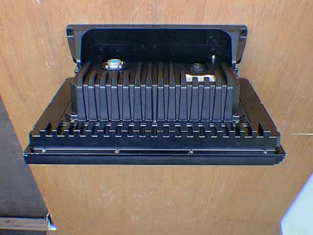
O5VRB718A
Oct 02, 2001Marine Radar RA54
Equipment Class
MRD - Marine Radar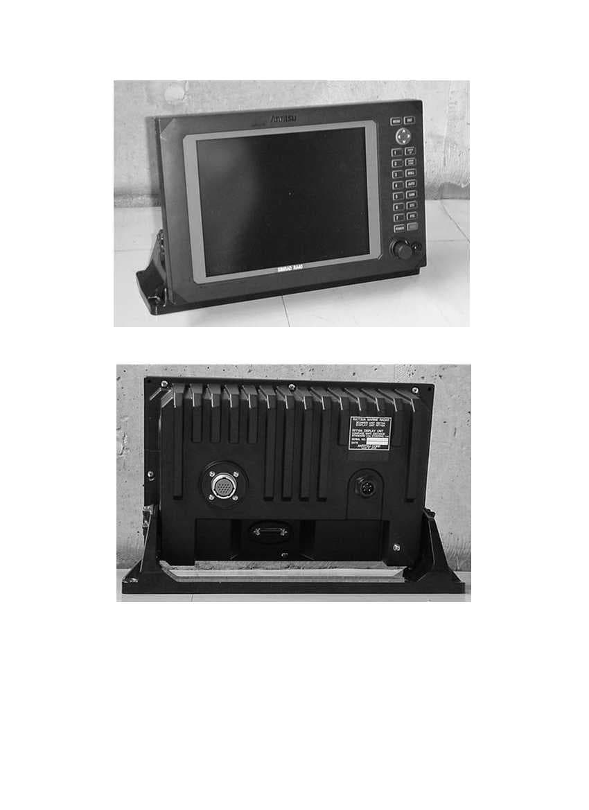
O5VRB714A
Dec 11, 2000Marine Radar RA40C
Equipment Class
MRD - Marine Radar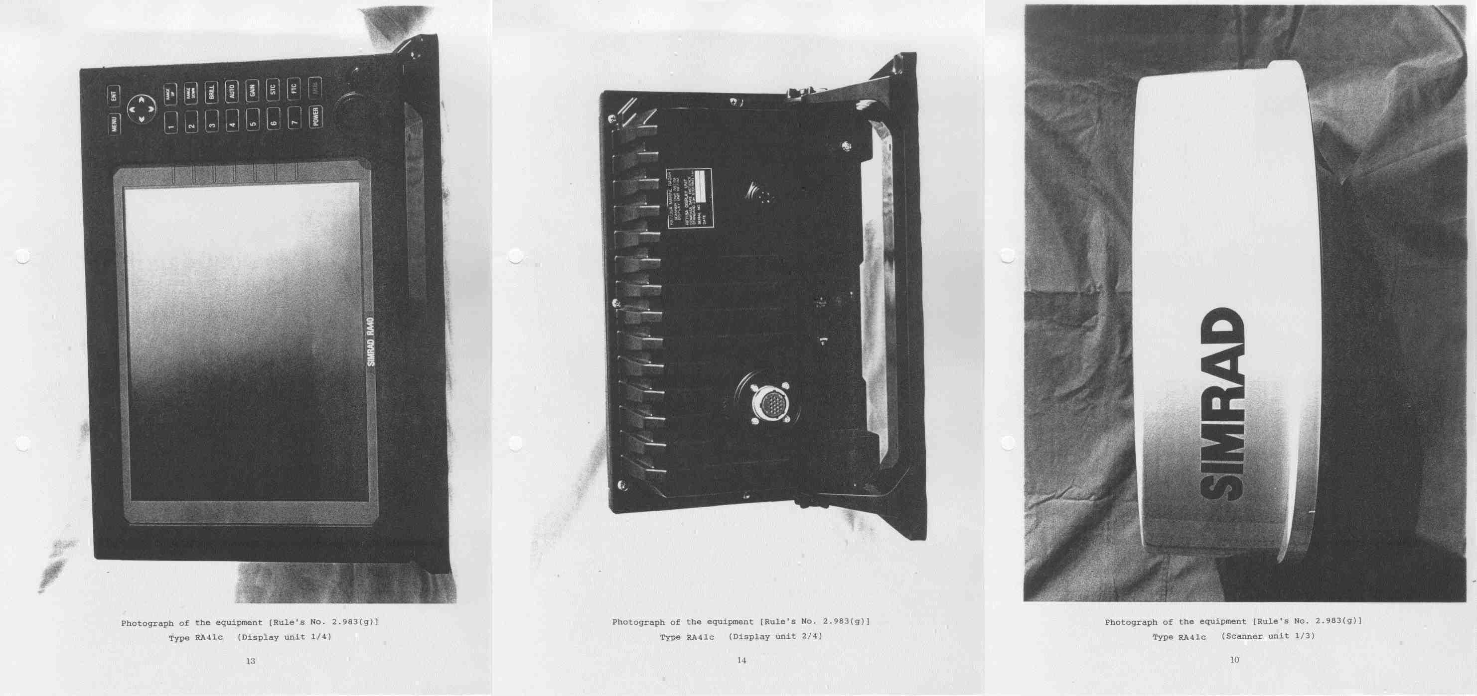
O5VRB715A
Dec 11, 2000Marine Radar RA41C
Equipment Class
MRD - Marine Radar