O5VRB717AMarine Radar RA53
Koden Electronics Co., Ltd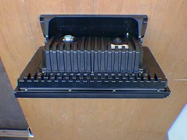
Click to zoom
Application Details
- Equipment Class
- MRD - Marine Radar
- Date of Grant
- Oct 02, 2001
- Application Purpose
- Original Equipment
- Date of Application
- Jul 05, 2001
- Equipment Note
- Marine Radar RA53
- Frequency Range
- 9300.00000000 - 9500.00000000
- Company
- Koden Electronics Co., Ltd
- Country
- Japan
Documents & Files
Document Text
Text extracted from the exhibit documents filed with the FCC. Open a document above to read the original.
Users Manual
1 To prevent the risk of personal injury or damage to the equipment, the following safety symbols are used to indicate safety-related information. Insure that you clearly understand the meanings of the symbols BEFORE using the equipment. Symbols Used in Manual This indicates a very dangerous procedure that could result in serious injury or death if not performed properly. This indicates a hazardous procedure that could result in serious injury or death if not performed properly. This indicates a hazardous procedure or danger that could result in light-to-severe injury, or that might damage the equipment, if proper precautions are not taken. Safety Symbols Used on Equipment The following safety symbols are used inside or on the equipment near operation locations to provide information about safety items and operation precautions. Insure that you clearly under- stand the meanings of the symbols and take the necessary precautions BEFORE using the equipment. This indicates high voltages with a risk of serious electric shock if the part is touched. NEVER touch the part with bare hands, etc. The symbol prohibits the operation shown inside the symbol. (The example in the left prohibits disassembly.) The symbol indicates that the operation inside the symbol is potentially hazardous. (The example on the left indicates that the plug should be held when disconnecting it from the AC outlet.) This indicates the ground (earth) terminal. If the equipment cannot be grounded via the power cord, connect this terminal to ground. There is a risk of serious electric shock if the equipment is not grounded. RA53/RA54 Marine Radar Instruction Manual 1st Jun. 2001 (1st Edition) Document: E-A53/54-1 Safety Symbols DANGER ! WARNING ! CAUTION ! 2 WARNING and CAUTION for Scanner Unit and Antenna ; 1. Do not approach the antenna while it is transmitting. In addition, at inspection never look into the wave guide during transmission. Distance at which RF power density level to become 100 W/m 2 : 2 m Distance at which RF power density level to become 10 W/m 2 : 6 m 2. There is a risk of receiving electric shock if these parts are touched by accident. Only qualified personnel should remove covers on these parts. WARNING for Display Unit ; There is a risk of receiving electric shock if these parts are touched by accident. Only qualified personnel should remove covers on these parts. For Safety 1. 2. 3 Installation Only qualified personnel should install the radar system in order to make sure proper radar performance and operation. To Customers * To always use this equipment at its best condition, we recommend observing the operation and main- tenance procedures in this manual from time to time. Further, try to operate the radar in good visibility condition to make comparison between visual impression and the radar picture presentation of the situation you are in. By doing this, you will be able to gain practical knowledge in interpreting the radar picture as well as the false echoes and blind sectors caused by the masts or funnel of the ship. Note that this equipment should only be used as a navigational aid and ship’s crew must make final decision on ship’s maneuvering. * In case of functional failure, immediately turn off the radar and switch off the ship’s main power supply at the distribution switchboard. Inform your local service agent of the faulty situation to detail, where pos- sible. * This instrument uses crystal oscillators and a LCD backlight lamp, which are vulnerable to mechanical shock. Take utmost care when handling these items * The mercury (Hg) is used in the LCD backlight lamp. When you attempt to discard your radar, observe the local code of practice for deposit. 4 Contents For safety CHAPTER 1 OVERVIEW.........................................................................8 1.1 Introduction............................................................................................................8 1.2 Organization of This Manual................................................................................8 CHAPTER 2 USING RADAR FOR THE FIRST TIME..........................9 2.1 What is a radar ?....................................................................................................9 2.2 Characteristics of Radar Wave.............................................................................10 2.3 Terms Specific to Radars.......................................................................................13 CHAPTER 3 INSTALLATION.................................................................16 3.1 Checking Contents of Your Package.....................................................................16 3.2 Checking Power Supply Voltage...........................................................................17 3.2.1 Power Supply Requirement.............................................................................17 3.2.2 Fuse Replacement.............................................................................................17 3.3 Determining Place of Installation.........................................................................18 3.3.1 Scanner unit......................................................................................................18 3.3.2 Display unit.......................................................................................................18 3.3.3 Shifting away from obstacles...........................................................................19 3.4 Installing Scanner Unit.........................................................................................20 3.5 Installing Antenna Unit........................................................................................21 3.6 Installing Display Unit..........................................................................................22 3.7 Connecting Cables.................................................................................................22 3.7.1 Interconnecti…
Text truncated - open the document above for the full version.
Users Manual
28 CHAPTER 4. FUNCTIONS AND NAMES Function and name of each part The RA53/54 radar consists of a display unit to display video images on a screen and a scanner unit configured with an antenna to radiate radio waves and other components. The display unit has on its front panel eighteen(18) push-switch keys and one cursor key that lets you move a cursor in any desired direction. A combination of these keys allows you to utilize all functions of your radar, providing a comfortable, easy way to operate. 4.1 Key layout Key No. SET1 SET2 SET3 SET4 1 EBL1 EBL2 DATA PPI 2 VRM1 VRM2 DEL PPI/3D 3 VAR RNG FL EBL2 ALL DEL PPI/PPI 4 TRACK FL VRM2 TRACK PPI/NAV 5 TARGET GZ ZOOM ALL PPI 6 SEL WIN OFF-C PICTURE ALL PPI2 7 NEXT NEXT NEXT NEXT Tab. 5 Function of soft key (Factory setting) *Every time Next key is pressed, soft key group switches as follows. SET1 → SET2 → SET3 → SET4 29 4.2 Rear panel 1. Power supply connector Use this connector to plug in the power supply cable. Standard NMEA interface terminal is included in this connector. Refer to Section 3.7 “ Connecting Cables “ and Section 3.9 “Connecting External Equipment to Display Unit “. 2. Grounding terminal Use this terminal to connect grounding wire. Refer to Section 3.7 (3) “Grounding wire”. 3. Option connector Use this connector to connect NMEA, an external monitor, external buzzer and GYRO I/F. A dedicated cable or dedicated module box is required to connect these pieces of equipment. Refer to Section 3.9 “Connecting Ex- ternal Equipment to Display Unit”. 4. Scanner connector Use this connector to plug in the inter-connecting cable to connect the scanner unit. Refer to 3.7 “Connecting cable “. 4.3 Radar screen( Single screen ) Ship’s position EBL2 VRM2 Indicate soft key 3 1 HU L 1:58 + RADAR OFF EBL1 VRM1 EBL2 VRM2 FL EBL2 FL VRM2 NEXT A HOLD ZOOM OFF-C LAT/LON 35°08. 42N 139°02. 53E 2 129. 8° 2 12. 34NM 0.23NM HDG 129.0 °T SPD 12.0 KT G 59 S AT F AT ST1 GZ IN TK 15 S WP 134.4 ° 12.5NM +LAT/LON 35°08.42N 139°02.53E 1 129. 8° 1 12. 3NM Tune meter Picture hold Zoom Off-center Range Range ring interval Display mode Heading angle Cruising speed Enlarging echo Guard zone Track Way point EBL1 VRM1 Pulse width Course error Gain STC FTC Cross cursor Cross cursor position (LAT/LON or Distance/Bearing) 30 4.4 Radar screen (Dual screen) ex) PPI/PPI screen 4.5 Radar screen (All PPI screen) Tune meter Picture hold Indicate soft key SPD 12.8KT GZ R IN WAY P 134.4° HDG 129.2° GZ L IN 12.5NM +MK 38.4° ST1 LAT 35°08.42N 2 129.8° 5.28 TK 15S LON 139°02.53E 2 3.62NM 6 1.0_ HU L .75 .25 EBL1 VRM1 EBL2 VRM2 FL EBL2 FL VRM2 NEXT A HOLD 0.23 XTE >>> 1 129.8° 1 12.34NM AT1 G 59 / AT S AT / AT F AT / AT Range(Left screen) Range(Right screen) Range ring interval Range ring interval (Left screen) (Right screen) Display mode Pulse width Cross cursor Course error EBL1 VRM1 + Cruising speed Guard zone(Right screen) Way point Heading angle Guard zone(Left screen) Cross coursor position Enlarging echo Ship’s position VRM2 (LAT/LON or Distance/Bearing) Track EBL2 AUTO (Left/Right) Gain (Left/Right) STC (Left/Right) FTC (Left/Right) 3 1 HU L GZ IN 1:58 + RADAR OFF OFF-C HOLD ZOOM Off-center Picture hold Zoom Range Range ring interval Display mode Guard Zone Pulse width Cross cursor 31 4.6 Radar screen (All PPI /PPI screen) 4.7 Navigation screen To show the NAV display, you need to connect a GPS receiver to your radar. The NAV display shows the position and cruising speed of your ship, seawater temperature, and other navigation information. Note: Heading angle will be displayed "COG" when C ourse Over Ground data is used. Note: Cruising speed will be displayed "SOG" when Speed Over Ground data is used. Deviation from Indication mark 0.00 -- >< 0.02 -- > or < 0.04 -- >> or << 0.08 -- >>> or <<< 0.16 -- >>>> or <<<< Tab.6 Indication of deviation from course Picture hold Guard zone(Right screen) Guard zone(Left screen) 6 1.0_ HU L GZ IN .75 .25 GZ IN HOLD Range(Left screen) Range(Right screen) Range ring interval Range ring interval (Left screen) (Right screen) + Display mode Pulse width Cross cursor NAV DISPLAY WP 134.4° COURSE 12.5 NM >>> HDG 129.0° 0.23 NM SPD 12.8 KT LAT 35°08.42N LON 139°02.53E TEMP 20.5° C DEPTH 93.2 M ST’BY Way point Heading angle Cruising speed Current position Sea water temperature Depth of water Course error (XTE) > Indicates starboarding the helm < Indicates porting the helm (left) 32 CHAPTER 5. OPERATION Basic operation of radar The RA53/54 radar has several fixed-function keys on the front panel. Press the relevant key to control these func- tions. Also, you can customize particular functions to the soft-keys. The following paragraphs explain the operation of each key. 5.1 Turning On and Off the radar (1) Turning On Press the "POWER" key. Buzzer sounds a short beep and then the radar system will be powered. Screen brilliance will be set to the level at which the radar system was turned off. (2) Turning off Keep pressing the "POWER" key more than 3 seconds, and then the radar system will be turned off. 5.2 Adjusting brilliance of screen and key-backlight (1) Press the "BRILL" key. A bar graph and figures appear in the lower left corner of the screen, indicating the screen brilliance. Under the screen brilliance figure, a figure indicating key-backlight brilliance will appear. (2) Adjust each item with the control knob. Items can be selected by the UP/DOWN cursor. (3) When the adjustment is finished, press either the "BRILL" key or the "ENT" key to exit from the adjustment screen. (Pressing some other key after adjustment will lead to the function of the pressed key.) BRILL → Control knob (Adjustment of brilliance) → BRILL or ENT → Up/Down (Selection of brilliance, key-backlight) → Other function key Move to other functions .75 .25 HU BRILLIANCE 50 ST’BY + KEY BACKLIGHT 4 33 5.3 Basic Operations xxx = Keys to press 5.3.1 Turning On and Off POWER Press POWER key to turn the radar on. The 2 minute countdown timer starts and the RADAR OFF sign will be …
Text truncated - open the document above for the full version.
Users Manual
46 5.5 MENU Operation List of MENU List of Main Menu MARK (MAIN-MENU) NAV (MAIN-MENU) ECHO (MAIN-MENU) SETUP (MAIN-MENU) EBL1 ON/OFF GAIN AUTO/MAN VRM1 ON/OFF MODE HU/HS/NU/CU/TM (MANU/NMEA) STC AUTO/MAN/HARBOR EBL2 ON/OFF GZ ON/OFF FTC AUTO/MAN WINDOW PPI / SEMI3D+PPI / PPI+PPI / PPI+NAV / ALL PPI / ALL PPI+PPI / MOB VRM2 ON/OFF OFF-C ON/OFF TUNE AUTO/MAN SEL WIN FL EBL2 ON/OFF ST OFF/ST1/ST2 PICTURE DAY/NIGHT FL VRM2 ON/OFF SLEEP OFF/5min/10min/ 15min SYSTEM CHECK HDG OFF OFF TRACK OFF/15SEC/30SEC/ 1MIN/3MIN/6MIN/ CONT ///CSR ON/OFF ZOOM ON/OFF RINGS ON/OFF SL SHORT/LONG VAR RNG ON/OFF TARGET CUSTOM KEY ASSIGNMENT PRESET1 (SUB-MENU) PRESET2 (SUB-MENU) NMEA PRESET ADJUST (SUB-MENU) +MK LINE ON/OFF List of Custom Menu PRESET1 (SUB-MENU) PRESET2 (SUB-MENU) HM FLSH ON/OFF GZ LEVEL 1-7 STERN M ON/OFF GZ MODE IN/OUT NORTH M ON/OFF HOLD ON/OFF ST’BY NAVI/NOR DISPLAY RDR/MONI/NAV BUZ VOL OFF/LOW/HIGH EXT BUZ OFF / CONT / INT RM UNIT NM / KM / SM IN P/R 1080/1024/2048/4096/360 DEPTH M / FT / FM OUT P/R 1080/1024/2048/4096/360 TEMP ° C / F DEMO ON / OFF EBL BRG REL / TRUE / MAG IR OFF / IR1 / IR2 WP BRG TRUE / MAG SPD SET NMEA / MANU 0.0 KT / LOG 200P HEAD INPUT NMEA / SIN, COS /12BIT / 10BIT LANGUAGE 15 countries HEAD TRUE / MAG SCAN SPEED STD / HIGH +MK MODE DIST/BRG / LAT/LON P TABLE 0 - 2 ADJUST (SUB-MENU) TIMING ADJ HEAD ADJ TUNING CAL. ANTENNA 1-9 GAIN 1-30 STC 1-16 ATA PRESET CPA SET 0.0 NM TCPA SET 0 MIN VECT SET. 6 MIN VECT MODE REL/TRUE ATA ON/OFF + ST’BY .75 . 25 HU STC > FTC > TUNE > ST > TRACK ZOOM S/L MARK NAV ECHO SETUP ECHO GAIN > MANU AUTO MAIN-MENU SUB-MENU 47 5.5.1 Mark Menu xxx = keys to press Setting for markers and cursors <Common operations for the MARK menu> (Up to the point when "MARK" menu is selected from the main menu) Press the "MENU" key and select "MARK" from the displayed 4 main menus using the left-right cursor. (The contents of the selected MENU will appear on a pull-down display in accordance with the movement of the left-right cursor.) MENU → Left/Right (Select MARK) Further explanations on the MARK menu are made assuming that "common operation for the MARK menu" has already been completed. 5.5.1.1 Bearing measurement (EBL1) (1) Select EBL1 from the pull-down display items using the up-down cursor key, and press the "ENT" key. (2) When the ON/OFF sign is displayed beside the letters EBL1, select ON with the up-down cursor keys and press the "ENT" key. (3) When you press the "ENT" key, an electric bearing line (EBL1) appears and the angle from the direc- tion of the ship’s head which is set at 0 degree will appear in a reverse display in the lower left corner of the screen. (4) Place the EBL on the center of the target with the rotary control and read out the bearing. You can use the EBL functions in the following modes. (a) Press the "ENT" key to show the EBL1 display still on the screen. (b) Press the "MENU" key without the EBL1 display. (c) Pressing another function key will lead to the function of that key with the EBL1 display still on the screen. Note: 1 xxx.x indicates the relative bearing measured by BL1. Up/Down → ENT → Up/Down → ENT → Control knob → ENT (a) (Select EBL1) (Select ON) (EBL1 operation) → MENU (b) →Other function key (c) Note: The displayed EBL angle is the relative bearing to ship’s heading or true bearing against true north, depending on the setting of "EBL BRG" in the "SETUP" menu. MARK EBL1 > VRM1 > EBL2 > .75 .25 HU NAV ECHO SETUP MARK >>> 0.23NM AT . 75 .25 HU + 1 0.0 ° OFF ON 48 5.5.1.2 Determining the distance (VRM1) (1) Select VRM1 from the pull-down display items using the up-down cursor key, and press the "ENT" key. (2) When the ON/OFF sign is displayed beside the letters VRM1, select ON with the up-down cursor keys and press the "ENT" key. (3) If you press the "ENT" key, the variable range marker1 (VRM1) and its distance in a reverse display appear in the lower left corner of the screen (See Note). (4) To measure the distance to a target, place the VRM1 on the front edge of the target with the rotary control and read the distance. (5) You can use the VRM1 functions in the following modes. (a) Press the "ENT" key to show the VRM1 display still on the screen (b) Press the "MENU" key without the VRM1 display. (c) Pressing another function key will lead to the function of that key with the VRM1 display still on the screen. Up/Down → ENT → Up/Down → ENT → Control knob → ENT (a) (Select VRM1) (Select ON) (VRM1 operation) → MENU (b) → Other function key (c) Note: 1 xx.xx NM indicates VRM1. 5.5.1.3 Bearing measurement (EBL2) Refer to the section “Bearing measurement (EBL1)”. The "EBL2" will appear in a reverse display in the lower right corner of the screen. Note: 2 xxx.x indicates the bearing measured by EBL2. 5.5.1.4 Determining the distance (VRM2) Refer to the section “Determining the distance (VRM1)”. The "VRM2" will appear in a reverse display at the lower right corner of the screen. Note: 2 xx.xx NM indicates the distance measured by VRM2. 5.5.1.5 Measuring the distance or angle between two points ( FL EBL2, FL VRM2 ) Determining the distance (VRM2) (a) Preparation for the measurement (1) Use the up-down cursor keys to select FL VRM2 from the pull-down display items, and press the "ENT" key. (2) Use the up-down cursor keys to select ON from the ON/OFF display beside the FL VRM2 items, and press the "ENT" key. The “SET START POINT” item will be shown and a small cross mark appears. (Once this is set, the "ON" state continues unless any other change is made.) Up/Down → ENT → Up/Down → ENT -----------------------FL VRM2 is turned ON and the small cross (Select FL VRM2) (Select ON) mark appears. (b) Setting a reference point for the distance measurement Use the left-right and up-down cursor keys to place the small cross mark on one of the two echoes whose distance is to be measured, and press the "ENT" key. Up/Down &Left/Right →-----------------------ENT Criterion of the reference point is set. (Place the cross cursor on an echo…
Text truncated - open the document above for the full version.
Users Manual
81 CHAPTER 6. MAINTENANCE AND INSPECTION A qualified engineer should carry out most of maintenance work on this radar. If your radar set has any problem, contact your local dealer for repair. Very High Voltage is present inside the radar set. Do not attempt to open the display rear cover or dis- assemble internal module. When you open the ra- dome, make sure to turn off the main power supply at switch board. Even if the radar is switched OFF, the radar set is still powered with very small amount of current. The following table shows the maintenance by user. Please check each item periodically. Tab. 6-1 Maintenance Articles of consumption The radar uses the life-limited parts as listed below that require periodic replacement. (1) Magnetron This part is used in the scanner unit. If distant echo images have become weak, the magnetron probably may have degraded. In such a case, you need to replace this item. Consult your local service agent for replacement. Practical life to replacement: 3000hour(typ.) (500hour guaranteed by the magnetron manufacturer) (2) LCD back-light This part used in the display unit. If the display screen is extremely dark and its illumi- nation cannot be corrected by adjusting the screen brightness, the LCD backlighting lamp may be faulty or may have burnt out. In such a case, you need to replace it. Consult your local agent for replacement. Period of the replacement: 15000 hours (typ.) (1000 hours at 0 °C ) Inspection Interval Inspection Item Method of Inspection and Maintenance 3-6 months Rust and looseness in scanner unit Check if the scanner’s fitting bolts are corroded. Display screen of LCD display Clean the filter plate and LCD screen surfaces with a soft and wet cloth. Avoid organic solvent. 6-12 months Grease application to antenna drive gear Apply an even coating of grease* to the entire surface of the antenna drive gear with a spatula or brush. Check for contact of connectors Check whether connectors are properly connected. If not, redo connection or make good contact by using a contact restoring chemical agent or by polishing or replace with a new one if necessary. Antenna motor brush(RA52/53/54) Check the length of brushes. If the length is less than 6mm, replace both brushes with new one. ! WARNING 82 (3) Fuse The fuse is in-line type, built in to the power supply cable. If the fuse appears to be blown, check the fuse. If blown, replace it following the procedure shown in Fig.6-2. Fig. 6-2 Method for replacing fuse Note: Before maintenance of scanner, you can hang a radome (upper) using cord through hole as fol- lows. Fig. 6-3 Method for replacing fuse Fixing screw Hole A: Top view Cord Cord A Radome(Upper) Radome(bottom) Push Power supply cable Wire(White) Turn counterclockwise and pull Fuse Spring Push and turn clockwise Replace new fuse To display unit 83 CHAPTER 7. TROUBLESHOOTING This chapter explains how to identify trouble locations when the radar is found faulty and how to request repair. If there is any trouble, press and hold the POWER key for 3 seconds to power off. Then turn on the equipment again and wait 10 sec at least. If you find the radar is faulty, check it by the following procedure described below. If you find as a result of inspection that the fault cannot be repaired on board, contact your distributor for repair. For faster service, please let us know about followings when you request repair: (1) Ship’s name, place of anchorage, allowable repair period or time (2) Radar type (This radar is RA53 or RA54.) (3) Manufacturing number (indicated on the back of the display unit) (4) Fault symptoms and inspection results There are high voltage circuits inside of this radar. Do not attempt to open the rear cover of display unit or disassemble internal parts. When you open the radome for installation, power must be off. Even if power switch is OFF, this radar is still sup- plied with power inside. This chapter explains how to identify trouble locations when the radar is found faulty and how to request repair. 7.1 Fault Diagnosis by Self-check The radar incorporates a failure diagnostic function (called "self-check") to diagnose faults by the equipment itself. Refer to "5.5.4.4 Fault Diagnosis by Self Check (SYSTEM CHECK)" and check whether there is any fault in your radar. ! WARNING 84 7.2 Inspecting Each Part When you have finished self-check, inspect each part of the radar according to Tab.7-1. Tab. 7-1 Troubleshooting Symptom Cause Corrective action (1) Radar cannot be powered on. Power cable is disconnected. Connect power cable correctly. Power supply voltage is outside of specified value Use Specified power supply. (See Section 3.2) Fuse in power cable is blown. Replace fuse. (See Chapter 6) (2) Nothing is displayed al- though radar is powered on. Brightness is improperly ad- justed. Use BRIL key to adjust. (See Section 5.3.) LCD is faulty. Contact your dealer. (3) Screen is dark. Brightness is improperly ad- justed. Use BRIL key to adjust. (See Section 5.3. Backlight is faulty. Contact your dealer. (4) Video does not appear al- though characters are displayed. Interconnecting cable is out of place. Connect interconnecting cable correctly. (5) Echo image on screen differs from actual image. Ship’s heading is incorrectly set. Set ship’s heading correctly. (See Section 5.5.4.5.4) Timing adjustment is incorrectly set. Set timing adjustment correctly. (See Section 5.5.4.5.4) (6) Echo images are blurred. GAIN, STC, or FTC is improp- erly set. Adjust. (See Section 5.3.6 to 5.3.8.) Magnetron has degraded. Contact your dealer. (7) Too much noise. Radar is not tuned correctly Adjust TUNE. (See Section 5.5.3.4) Radar set is not grounded to earth. Connect grounding wire. (See Section 3.4 to 3.6.) (8) No response to key pressing. Panel keys are not in contact. Contact your dealer. Power supply circuit is faulty. Contact your dealer. 85 CHAPTER 8. PRODUCT SPECIFICATIONS 8.1 General Type: RA53 and RA54 Power supply voltage and power consumption Power…
Text truncated - open the document above for the full version.
Attestation Statements
APPLICATION FOR FCC TYPE ACCEPTANCE MARINE RADAR RA53 KODEN ELECTRONICS CO., LTD INFORMATION TO MAKE APPLICATION FOR MARINE RADAR TO FCC TYPE ACCEPTANCE 1. General Information 1.1 Kind of Application Certificate of Radar Equipment 1.2 Kind of Equipment Marine Radar 1.3 Type of Equipment Type RA53 2. Contents in this document 2.1 ID Label/Location Information External Photos Schematics Internal Photos 2.2 Operational Description 2.3 Parts List/Tune Up Information 2.4 Test Data 2.5 Instruction Manual
External Photos
External Photos ( RB717A Scanner Unit ) Front View Rear View Side View External Photos ( RF720A Display Unit ) Front View Side View Top View Rear View
ID Label/Location Info
ID Label/Location Info FCC ID Label
ID Label/Location Info
ID Label/Location Info FCC ID Label
Internal Photos
Internal Photos 1. Scanner Unit ( RB717A) Internal Photos 2. Display Unit ( RF720A)
Operational Description
Operational Description MARINE RADAR RA53 1. A description of all circuitry and devices provided determining and stabilizing frequency. Rule's No. 2.983(d)-(10) 1.1 The oscillating frequency stability of pulsing magnetron depends upon the load characteristics. In this radar, the load of the magnetron consists of a duplexer, a waveguide feeder and an antenna, and the load is matched to the magnetron. The VSWR of the load is better than 1.25 within the specified frequency range. 1.2 Receiver The oscillating frequency stability of FET local oscillator depends upon the supply voltage and ambient temperature. For obtaining the desired frequency stability of oscillator, following means are provided. In addition this radar equips an automatic tuning circuit to coincide the receiver frequency with the transmission frequency. 1.2.1 Temperature compensation High Q strip line of the oscillator circuitry is employed in the Front-End module due to temperature compensation. 1.2.2 Stabilizing the power supply DC voltage supplied to the FET local oscillator is stabilized by the regulator. DC voltage across the varactor diode for tuning is supplied from a D/A converter. The voltage across the D/A converter is made by dividing the regulated 24 volts DC. The regulated voltage is generated by regulator on power supply unit. Therefore stable oscillation can be obtained. 2. A description of any circuits or devices employed for suppression of spurious radiation , for limiting modulation, and for limiting the operating power. Rule's No. 2.983(d)-(11) 2.1 Circuits or devices employed for suppression of spurious radiation. 2.1.1 Suppression of spurious radiation from antenna A duplexer, a waveguide feeder and an antenna perform the narrow band-pass filter and all the spurious signals outside the radar frequency band are 1 suppressed -50dB lower than main radiation level. 2.1.2-1 Line filters The line filters are provided on the ship's power supply line as follows; Line filter L6-L9 and capacitors C11-C14, and C87-C88 on POWER PCB in the display unit. 2.1.2-2 Special inter-unit connection cable A special 12 cores cable shielded by the metal braid is employed for the inter-unit connection and the grounding of the braid are made surely at both ends. 2.2 Circuits or devices for limiting the modulation and operating power Transmitting tube, pulsing magnetron, operates with negative going high voltage pulse in the modulator. DC 250 volts as the modulator source generated by the DC-DC converter with voltage regulator(power supply unit) is supplied to the modulator to generate the modulating pulse with constant amplitude. Accordingly, modulation and transmitter power level are maintained constant.
Parts List/Tune Up Info
Parts List/Tune Up Information MARINE RADAR RA53 Technical description that is not described on FCC Form 731 and an attached instruction book for Type RA53. 1. Function of each electron tube, semiconductor or other active circuit device Rule's No.2.983 (d) - (6) 1.1 Electron tubes Symbol No. Description Type Function V101 Magnetron MSF1422B Transmitting tube 1.2 Semiconductor in the chassis of the scanner unit Symbol No. Description Type Function U101 Front end with X-band amplifier NJT1973 RF amplifier, local oscillator and mixer U1 Limiter diode NJS6930 Receiver protector at X-band 1.3 Semiconductor on E41-100*(Modulator) Symbol No. Description Type Function CR1,CR3 Diode 1SS123-L Rectifier CR2, CR4, CR5, CR6, CR7, CR10, CR14 Zener Diode HZM5.1NB2TL Voltage limiter CR8 Zener Diode HZM9.1NB1TL Voltage limiter CR9 Zener Diode HZM6.2NB2TL Voltage limiter CR11, CR15 Diode SB90-05J Voltage limiter CR12 Diode DCB010TA Rectifier CR13 Diode V06G Rectifier Q1, Q6 Transistor 2SA1182-Y-TE 85L Video/Trigger amplifier Q2 Transistor 2SD1005-T1 Video amplifier 1 Symbol No. Description Type Function Q3 Transistor 2SA1213-TE12 L Video amplifier Q4, Q8 Transistor 2SA1462-T1BY 34 Trigger buffer amplifier Q5, Q7, Q9 Transistor 2SC3735-T1BB 35 Pulse amplifier Q10, Q28 Transistor 2SC3736-T10L Pulse amplifier Q11, Q29, Q31 Transistor 2SA1463-T1IL Pulse amplifier Q18 FET 2SK738-Z-E1 Pulse amplifier Q19 FET 2SJ132-Z-T1 Pulse amplifier Q14 Transistor 2SC3631-Z Pulse amplifier Q21, Q22, Q23, Q24 FET 2SK1450 Pulse switch Q16 Transistor 2SA1413-Z-T2 K Buffer amplifier Q25, Q27 Transistor 2SC2712-YTE8 5L Voltage regulator Q26 Transistor 2SB596-O Voltage regulator Q30 FET IRFP150N Motor driver U1 IC Regulator LM350K Magnetron heater driver U2 IC TC74HC14AF Hex-inverter U3 IC Regulator HA17815V Voltage regulator U4 IC Regulator HA17805V Voltage regulator U5 IC TC74HC00AF-E L Quad- 2input NAND gate U6 IC MC14046BCF Azimuth PLL U7 Transistor Array TD62004F Signal buffer U8, U9 IC TC74HC4040AF 12 bit binary counter U10 IC Custom AC235AFP Transceiver controller U11 IC TC74HC11AF-T P2 Triple 3 input AND gate 2 Symbol No. Description Type Function U12, U13 A/D converter TC35095AF System check interface U14 Ope-amplifier UPC324G2-E2 Analog interface U15, U16, U17, U19 Photo coupler TLP181GB Ground isolator U18 IC UPC494GS-E2 Motor Power supply controller 1.4 Semiconductor on E41-200*(IF amplifier) Symbol No. Description Type Function CR1, CR2, CR5, CR7 Diode 1SS123-L Switch,…
Text truncated - open the document above for the full version.
Contact Information
Applicant
Kazuhiro Moriguchi(General Manager, Engineering Department)
Technical Contact
Koden Electronics Co., Ltd.Hiroyuki Iida
[email protected]+81-554-20-5868
1500 Northwest 1st Street · Yamanashi, Florida · United States
Non-Technical Contact
SIMRAD INC.Brian Vlad
[email protected]954-922-7700
Technical Specifications
| # | Rule Parts | Frequency Range | Power Output | Emission |
|---|---|---|---|---|
| 1 | 80 | 9.30 GHz - 9.50 GHz | 6000 W | 95M4P0N |
Other Applications from Koden Electronics Co., Ltd
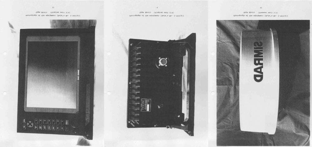
O5VRB715L
Oct 21, 2003MODEL RA41C RADAR
Equipment Class
MRD - Marine Radar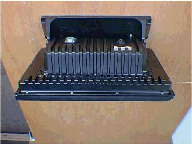
O5VRB719A
Nov 24, 2002Marine Radar RA55
Equipment Class
MRD - Marine Radar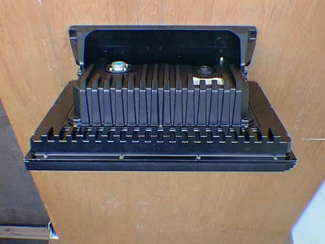
O5VRB718A
Oct 02, 2001Marine Radar RA54
Equipment Class
MRD - Marine Radar
O5VRB714A
Dec 11, 2000Marine Radar RA40C
Equipment Class
MRD - Marine Radar
O5VRB715A
Dec 11, 2000Marine Radar RA41C
Equipment Class
MRD - Marine Radar