O5VRB719AMarine Radar RA55
Koden Electronics Co., Ltd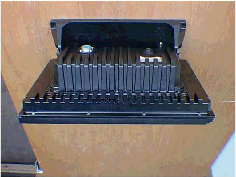
Click to zoom
Application Details
- Equipment Class
- MRD - Marine Radar
- Date of Grant
- Nov 24, 2002
- Application Purpose
- Original Equipment
- Date of Application
- Sep 02, 2002
- Equipment Note
- Marine Radar RA55
- Frequency Range
- 9300.00000000 - 9500.00000000
- Company
- Koden Electronics Co., Ltd
- Country
- Japan
Documents & Files
Document Text
Text extracted from the exhibit documents filed with the FCC. Open a document above to read the original.
Users Manual
KODEN ELECTRONICS CO.,LTD. 5278 UENOHARA, UENOHARA-MACHI,KITATSURU-GUN, YAMANASHI, 409-0112, JAPAN TEL: +81 554 20 5865 FAX: +81 554 20 5880 http://www.koden-electronics.co.jp/ INSTRUCTION MANUAL MARINE RADAR RA51/52/53/54/55 E-A51/52/53/54/55-2 PRINTED IN JAPAN
Users Manual
RA51/52/53/54/55 INSTRUCTION MANUAL – 05 i To prevent the risk of personal injury or damage to the equipment, the following safety symbols are used to indicate safety-related information. Be sure that you clearly un- derstand the meanings of the symbols BEFORE using the equipment. Symbols Used in Manual This indicates a very dangerous procedure that could result in serious injury or death if not performed properly. This indicates a hazardous procedure that could result in serious injury or death if not performed properly. This indicates a hazardous procedure or danger that could result in light-to-severe injury, or that might damage the equipment, if proper precautions are not taken. Safety Symbols Used on Equipment The following safety symbols are used inside or on the equipment near operation lo- cations to provide information about safety items and operation precautions. Insure that you clearly understand the meanings of the symbols and take the necessary precau- tions BEFORE using the equipment. This indicates high voltages with a risk of serious electric shock if the part is touched. NEVER touch the part with bare hands, etc. The symbol prohibits the operation shown inside the symbol. (The example on the left prohibits disassembly.) The symbol indicates that the operation inside the symbol is potentially hazardous. (The example on the left indicates that the plug should be held when disconnecting it from the AC outlet.) This indicates the ground (earth) terminal. If the equipment cannot be grounded via the power cord, connect this terminal to ground. There is a risk of serious electric shock if the equipment is not grounded. RA51/RA52/RA53/RA54/RA55 Marine Radar Instruction Manual 25th March 2002 (8th Edition) 1st Apr. 2001 (1st Edition) Document: E-A51/52/53/54/55-2 Safety Symbols DANGER ! WARNING ! CAUTION ! ii RA51/52/53/54/55 INSTRUCTION MANUAL – 05 WARNING and CAUTION for Scanner Unit and Antenna; 1 Do not approach the antenna while it is transmitting. In addition, at inspection never look into the wave-guide during transmission. Distance at which RF power density level to become 100 W/m 2 0.8 m Distance at which RF power density level to become 10 W/m 2 : 8 m 2 There is a risk of receiving electric shock if these parts are touched by accident. Only qualified personnel should remove covers on these parts. WARNING for Display Unit; There is a risk of receiving electric shock if these parts are touched by accident. Only qualified personnel should remove covers on these parts. For Safety 1 2 RA51/52/53/54/55 INSTRUCTION MANUAL – 05 iii Installation Read and understand the manual thoroughly before installing this unit. To The User * Read and follow the operation and maintenance procedures in this manual. Note that this equipment is only a navigational aid. There is no warranty for navigational safety. It is no sub- stitute for prudent navigational procedure and should not be relied on solely for passage. * If this equipment does not operate properly, immediately turn off the power switch and disconnect the main power supply. Notify your authorized Simrad dealer or technical service center as soon as possible. * The liquid crystal display as well as some of the internal components of this radar can be dam- aged by dropping or excessive force due to impact. Mount the unit so that it will not be subject to these forces. * Mercury (Hg) is used in the LCD backlight. When the unit is taken out of service, it should be disposed of according to local regulations regarding hazardous materials.
Users Manual
iv RA51/52/53/54/55 INSTRUCTION MANUAL – 05 Contents For safety CHAPTER 1 OVERVIEW....................................................................1 1.1 Introduction --------------------------------------------------------------------------------------1 1.2 Organization of This Manual ----------------------------------------------------------------1 CHAPTER 2 USING RADAR FOR THE FIRST TIME.........................2 2.1 What is radar? ----------------------------------------------------------------------------------2 2.2 Characteristics of Radar Wave -------------------------------------------------------------3 2.3 Terms Specific to Radars --------------------------------------------------------------------6 CHAPTER 3 INSTALLATION.............................................................9 3.1 Checking Inventory-----------------------------------------------------------------------------9 3.2 Checking Power Supply Voltage----------------------------------------------------------10 3.2.1 Power Supply Requirement---------------------------------------------------------------------------------10 3.2.2 Fuse Replacement---------------------------------------------------------------------------------------------10 3.3 Where to install the Scanner---------------------------------------------------------------11 3.3.1 Scanner unit-----------------------------------------------------------------------------------------------------11 3.3.2 Display unit------------------------------------------------------------------------------------------------------11 3.3.3 Shifting away from obstacles--------------------------------------------------------------------------------12 3.4 Installing Scanner Unit-----------------------------------------------------------------------13 3.5 Installing Antenna Unit-----------------------------------------------------------------------15 3.6 Installing Display Unit-------------------------------------------------------------------------15 3.7 Connecting Cables----------------------------------------------------------------------------16 3.7.1 Interconnecting cable (RA51 Radome scanner)-----------------------------------------------------------16 3.7.2 Interconnecting cable (RA52/53/54/55 Open scanner)--------------------------------------------------18 3.7.3 Grounding wire-----------------------------------------------------------------------------------------------------19 3.7.4 Power supply cable-----------------------------------------------------------------------------------------------20 3.8 Adjustment--------------------------------------------------------------------------------------20 3.9 Connecting External Equipment to Display Unit---------------------------------------21 3.10 Countermeasure for Electromagnetic Interference-----------------------------------21 3.11 When Discarding Your Radar--------------------------------------------------------------22 CHAPTER 4 FUNCTIONS AND NAMES..........................................23 4.1 Key layout---------------------------------------------------------------------------------------23 4.2 Rear panel---------------------------------------------------------------------------------------24 4.3 Radar screen (Single screen)--------------------------------------------------------------24 4.4 Radar screen (Dual screen)----------------------------------------------------------------25 4.5 Radar screen (All PPI screen)-------------------------------------------------------------25 4.6 Radar screen (All PPI/PPI screen)--------------------------------------------------------26 4.7 Navigation screen-----------------------------------------------------------------------------26 RA51/52/53/54/55 INSTRUCTION MANUAL – 05 v CHAPTER 5 OPERATION................................................................27 Basic operation of Radar---------------------------------------------------------------------------27 5.1 Powering ON and OFF----------------------------------------------------------------------27 5.2 Adjusting contrast and brilliance of the screen, and key-backlight---------------27 5.3 Basic Operations------------------------------------------------------------------------------28 5.3.1 Turning On and Off---------------------------------------------------------------------------------------------28 5.3.2 Transmitting------------------------------------------------------------------------------------------------------28 5.3.3 Adjusting contrast and brilliance of the screen, and key-backlight---------------------------------28 5.3.4 Changing the range scale (RANGE UP, RANGE DOWN)-------------------------------------------28 5.3.5 Automatic adjustment (AUTO)------------------------------------------------------------------------------29 5.3.6 Sensitivity adjustment (GAIN)-------------------------------------------------------------------------------29 5.3.7 Removing Sea clutter (STC)------------------------------------------------------------------------------------30 5.3.8 Removing rain and snow clutter (FTC)--------------------------------------------------------------------30 5.3.9 Man Over Board (MOB)---------------------------------------------------------------------------------------30 5.4 Soft Key Functions----------------------------------------------------------------------------31 5.4.1 Bearing measurement (EBL1)-------------------------------------------------------------------------------31 5.4.2 Bearing measurement (EBL2)-------------------------------------------------------------------------------31 5.4.3 Distance measurement (VRM1)----------------------------------------------------------------------------31 5.4.4 Distance measurement (VRM2)----------------------------------------------------------------------------31 5.4.5 Measuring the angle between two points (FL EBL2)--------------------------------------------------31 5.4.6 Measuring the distance between two points (FL VRM2)------------------------…
Text truncated - open the document above for the full version.
Users Manual
RA51/52/53/54/55 INSTRUCTION MANUAL – 05 1 CHAPTER 1 OVERVIEW 1.1 Introduction The RA51/52/53/54/55 is compact marine radar that delivers a peak antenna power output of either 4 kW (RA51/52), 6 kW (RA53), 12 kW (RA54) or 25 kW (RA55) and has a 15-inch color 640 x 480 liquid crystal display. It uses a microcomputer and a video signal processing LSI chip specifically designed for radars to deliver high performance and a wide range of features. Features 1. The LCD allows for a thin case, permitting installation in tight quarters. 2. Minimal keys and menu screens mean you can easily learn to use the radar. 3. On screen soft key functions are user assignable. 4. Continuously variable adjustments are done with a rotary knob. 4. The dual range mode allows you to see short and long-range echoes simultaneously. 5. The Semi-3D display allows for easy identification of targets in noise. 6. A variable range function allows for smooth range changes, not in steps. 7. Waterproof construction (IPX-5) of the display allows installation on open boats. 1.2 Organization of This Manual This manual provides information for both the novice and experienced user to install, operate and maintain the RA51/52/53/54/55 radar. Please read it thoroughly so you can take full ad- vantage of its advanced functions. If you are using radar for the first time, begin with the background information on how radar works in CHAPTER 2. USING RADAR FOR THE FIRST TIME ...................... CHAPTER 2 INSTALLATION ...................... CHAPTER 3 FUNCTIONS AND NAMES ...................... CHAPTER 4 OPERATION ...................... CHAPTER 5 INSPECTION AND MAINTENANCE ...................... CHAPTER 6 TROUBLESHOOTING ...................... CHAPTER 7 PRODUCT SPECIFICATIONS ...................... CHAPTER 8
Users Manual
2 RA51/52/53/54/55 INSTRUCTION MANUAL – 05 CHAPTER 2. USING RADAR FOR THE FIRST TIME This chapter covers basic information and technical terms about radar for those who are using one for the first time. 2.1 What is radar? RAdio Detecting And Ranging The word "radar" is an acronym for "RAdio Detecting And Ranging." In very simple terms, this is how it works. A radio transmitter sends a quick microwave pulse, and then a receiver listens for that signal's echo when it is bounced back from something in its path. The returning signal is processed by a computer to determine its relative distance, position and bearing. This information is graphically displayed on a screen for you to see. Other boats or ships, navigational markers, landmasses and such are referred to as targets. By knowing how long it takes for a signal to return, the distance to a target can be determined. As the radar antenna scans through a 360-degree rotation, it can show where the target is relative to your position. By repeated scans, you can see which direction another vessel is moving. Fig.2-1 What is radar? Antenna How radar will perform is largely determined by its antenna or scanner. Increasing the size of the antenna improves long-range performance and target discrimination, or the ability to distinguish two separate targets at a distance. The critical factors are the antenna's beam width and side lobe level. Typically, a radar antenna will radiate a tightly focused beam from the front of the array. The longer the antenna array is, the narrower the beam width will be. Additionally, it will also emit smaller amounts of energy to each side. The lower the side lobe level, the less the effect of a false echo. The RA51 radars are equipped with a closed dome scanner, the RA52/53/54/55 has a larger, open array. Side lobe The beam in which the strongest radio signal is radiated from the antenna is called the “main lobe”. Those beams that are radiated in other directions are referred to as the “side lobes”. The side lobe level refers to the difference in level (signal strength) between the largest side lobe and the main lobe. Fig.2-2 Antenna pattern Buoy Other ship Radar wave Your ship Antenna Radar display Beam width Side lobe level Main beam Side lobe Antenna RA51/52/53/54/55 INSTRUCTION MANUAL – 05 3 2.2 Characteristics of Radar Wave Radio waves travel out from the antenna while bending slightly along the earth's surface. The amount they bend depends on atmospheric conditions. The sight distance of a radar generally is about 6% longer than the optical sight distance and is calculated using this equation: Radar sight distance (NM) = 2.22 ( antenna height (m) + target height (m)) Fig.2-3 Radar wave Targets difficult to display on screen The intensity of the reflected radio signal from a target depends on the distance, height, and size of the target, as well as its material and shape, along with the radar’s transmitter power output and antenna size. Targets made of fiberglass, wood, or other low-reflectance materials or those that have a small incident angle are difficult to display on a screen. Sandy beaches, and sandy or muddy shallows can be difficult to catch. Because there's not much to reflect a signal back to you, a coastline can actually be closer to your boat than it appears on the screen. Fig.2-4 Targets difficult to display on screen Shadow zones of radar Radar waves propagate in a straight line. A high outcropping of land or a large ship will create a shadow zone behind it and prevent you from seeing targets on the other side. More importantly, if a mast or some part of the boat's superstructure is in the path of the antenna's sweep, this will also create a shadow zone. No targets will be recognized behind it and it could create a dangerous situation. False echoes Sometimes radar will display targets on screen that do not exist in the real world. You should be aware of how and why this happens. A. Ghost echoes Sometimes one large object very near your boat will appear as two different targets onscreen. One is the actual radar echo. The other is a ghost echo generated by a re-reflection of the original signal. It comes back to your own boat, bounces back to the target, and then is picked up by the h1 h2 Line of sight Radar Radio Wave Earth Apparent coastline Actual(invisible) coastline Invisible Visible 3 1 HU 4 RA51/52/53/54/55 INSTRUCTION MANUAL – 05 antenna on the second bounce. The actual echo appears at the correct distance and bearing on the screen. The ghost echo appears somewhere behind your boat. This type of false echo is also gen- erated by re-reflection of waves from bridges, quay walls or building along shore. Fig.2-5 False echoes of radar (Ghost echoes) B. Multiple echoes If there is a large vertical reflecting surface near your boat, as in the case when you pass alongside a large ship, radar signals are repeatedly bounced back and forth between your boat and the other object. Two to four images appear on the screen at equal intervals in the same bearing. This is called a multiple echo. The image appearing closest to you is the real echo. Multiple echoes will disappear as you move away from the reflecting object or its bearing changes. Fig.2-6 False echoes of radar (Multiple echoes) C. False echoes caused by side lobe An antenna's side lobe emissions are low power, and will not register distant targets. However, if there is a strong reflecting target near your boat, it sometimes may appear as a circular-arc false echo on the screen. When near large targets or land, your boat's mast may sometimes appear as a circular-arc shaped false echo. CAUTION ! Target Direct reflection path Secondary reflection path Mast etc. Real echo Ghost echo Direction of ghost echo 3 1 HU 3 1 HU Real echo Multiple echoes RA51/52/53/54/55 INSTRUCTION MANUAL – 05 5 Fig.2-7 False echoes of radar (Caused by side lobe) D. Distant false echoes caused by duct phenomenon The duct phenomenon sometimes occurs when meteorological condit…
Text truncated - open the document above for the full version.
Users Manual
RA51/52/53/54/55 INSTRUCTION MANUAL – 05 9 CHAPTER 3. INSTALLATION This chapter shows how to install the RA51/52/53/54/55 radar on your boat and the precau- tions you'll need to observe. 3.1 Checking Inventory ___________________________________ Carefully unpack the box and check to see that all components are present. RA51 RA52 RA53 RA54 R55 Item Q'TY Q'TY Q'TY Q'TY Q'TY Display unit 1 (RF720A) 1 (RF720A) 1 (RF720A) 1 (RF720A) 1 (RF720B) Scanner unit 1 (RB715A) 1 (RB716A) 1 (RB717A) 1 (RB718A) 1 (RF719A) Display cover 1 1 1 1 1 Fuse 2 2 2 2 2 Interconnecting cable 1 (10 m) 1 (10 m) 1 (10 m) 1 (10 m) 1 (15 m) Power supply cable 1 (2 m) 1 (2 m) 1 (2 m) 1 (2 m) 1 (2 m) M10 hexagonal bolt 4 sets 0 0 0 0 M12 hexagonal bolt 0 4 sets 4 sets 4 sets 4 sets Motor brush 0 2 2 2 2 Your unit was shipped with a 10m(or 15m) interconnecting cable. Longer or shorter cable is also available as an option, as listed in Tab.3-1. Checking contents of your package Checking power supply voltage Determining place of installation Installing scanner unit Installing display unit Connecting cables Adjustment Connecting external equipment When discarding Your radar 10 RA51/52/53/54/55 INSTRUCTION MANUAL – 05 Tab.3-1 Optional Interconnecting Cable You'll need to supply the following hardware: Item QTY Remarks Tapping screw or M5 bolt and nut 6 sets To install display unit Grounding wire 1 Earth line for display unit Grounding wire and crimp terminal 1 set Earth line for scanner unit 3.2 Checking Power Supply Voltage___________________________ 3.2.1 Power Supply Requirements Tab.3-2 shows the power requirements for the RA51/52/53/54/55 radar. If the unit is supplied with less than the specified voltage, it won't operate properly. Keep in mind that when the unit is initially powered on there will be a peak current surge. Check all circuits back to the power source for correct wire gauge and tight connections. Tab.3-2 Power Supply Requirements *A.C. power cannot be used 3.2.2 Fuse Replacement CAUTION: Use only exact replacements. Tab.3-3 Supply Voltage vs. Fuse Ratings Main Fuse Motor Fuse 15A/250V or 125V * (6.3F x 32mm) T3.15A/250V or 125V (5F x 20mm) RA51 RA52/53/54 RA55 Cable length Product No. Product No. Product No. 10m(If you need) 242J158055A 15m 242J158055B 242J159098B 20m 242J158055C 242J159098C 242J159098C 30m 242J158055D 242J159098D 242J159098D Supply voltage used Maximum current Allowable range of voltage DC12V 14A 10.2-41.6V DC24V 6A 10.2-41.6V DC24V (for RA55) 15A 18.0-41.6V RA51/52/53/54/55 INSTRUCTION MANUAL – 05 11 3.3 Where to Install the Scanner_____________________________ 3.3.1 Scanner unit Radar's target detection capacity varies greatly depending on the position of the scanner. An ideal position is a location high above the ship's keel line where there is no obstacle all around the scanner. In an actual ship, such an ideal location is limited by various factors. To comply with FCC RF exposure requirements, the radar antenna for this scanner must be installed to provide a separation distance of 1.3 m or more from all persons. (a) Install the scanner as high as possible. Consider the structural support of the location. Will it hold the weight of the scanner? How difficult will it be to get to the scanner for maintenance? (b) Install the scanner away from masts. If the scanner is installed at the same height as a mast, radar waves may be blocked, creating shadow zones or generating false echoes. (c) Install the scanner forward of obstacles. If you can't avoid an obstacle, place the scanner on the bow side of it. When installing the scanner on a mast, position it in front of the mast. (If obstacles cannot be avoided for structural reasons, refer to "Shifting away from obstacles" in Section 3.3.3.) (d) Do not install the scanner near hot or heat-generating items. Do not install the scanner where it may be subjected to smoke or hot air from exhausts or heat from lights. (e) Install the scanner away from other antennas. Keep it as far as possible from the antennas of other electronic equipment. Radar scanners will cause interference with radio transceivers. Keep them as far apart as possible (f) Keep the cable length as short as possible. Keep the distance from the scanner to the display unit within the standard cable length of 10 m (or 15m). If you need a longer cable, limit the length to a maximum of 100 m. 3.3.2 Display unit The display unit can be installed in a helm console, bulkhead, or electronics box. Consider these suggestions: (a) A place where you can see the boat's bow when looking straight up from the radar screen. (b) A place where there is no direct sunlight to avoid display temperature buildup. (c) A place where there is good ventilation and minimum vibration. (d) A place where the display unit is more than the minimum safe distance from a magnetic compass as listed in Tab.3-5 below. Tab.3-5 Minimum Safe Distance from Magnetic Compass Standard compass Steering compass Scanner unit 2.0m 1.4m Display unit 2.0m 1.4m ! CAUTION 12 RA51/52/53/54/55 INSTRUCTION MANUAL – 05 3.3.3 Shifting away from obstacles Å Shifting from keel line By shifting the scanner position from the keel line to the starboard side of the boat, it is possible to move shadow zones to the port side. This makes it possible to keep a clear view to the bow. The distance to be shifted can calculated using the following equation: Ls=0.4R+D/2 [m] (when R<15m) Ls=0.025R+D/2 [m] (when R>=15m) where Ls = distance to be shifted from keel line D = diameter of obstacle on keel line R = distance from scanner to obstacle Fig.3-1 Shifting from keel line Ç Obtaining sufficient dip angle Raise the scanner position so that there is a sufficient dip angle θ available between the line of sight from the scanner to the obstacle and the horizontal line. By raising the dip angle above 5 ° , it is possible to prevent mid- and long-distance shadow zones. The radar cannot detect objects below the line of sight. Fig.3-2 Obtaining sufficient dip angle…
Text truncated - open the document above for the full version.
Users Manual
RA51/52/53/54/55 INSTRUCTION MANUAL – 05 23 CHAPTER 4. FUNCTIONS AND NAMES The RA51/52/53/54/55 radar consists of a display and a scanner. The display unit has on its front panel eighteen push-button keys, one rotary control knob and one cursor control touch pad. 4.1 Key layout____________________________________________ Key No. SET1 SET2 SET3 SET4 1 EBL1 EBL2 DATA PPI 2 VRM1 VRM2 DEL PPI/3D 3 VAR RNG FL EBL2 ALL DEL PPI/PPI 4 TRACK FL VRM2 TRACK PPI/NAV 5 TARGET GZ ZOOM ALL PPI 6 SEL WIN OFF-C PICTURE ALL PPI2 7 NEXT NEXT NEXT NEXT Tab. 5 Function of soft key *Every time the "NEXT" soft key is pressed, the soft key group changes as follows: SET1 → SET2 → SET3 → SET4 24 RA51/52/53/54/55 INSTRUCTION MANUAL – 05 4.2 Rear panel____________________________________________ Å Power supply connector The wires in the cable that attaches to this connector supply both power and NMEA interface data. Refer to Section 3.7.4 “ Power Cables “ and Section 3.9 “Connecting External Equipment to Display Unit “. Ç Grounding terminal Use this terminal to connect grounding wire. Refer to Section 3.7.3 “Grounding wire”. É Option connector Connect an NMEA data source, an external monitor, external buzzer or GYRO I/F here through an optional connector or using a junction box. Refer to Section 3.9 “Connecting External Equipment to Display Unit”. Ñ Scanner connector This connector is for the cable that runs between the display and the scanner. Refer to 3.7 “Connecting cable “. 4.3 Radar screen (Single screen)____________________________ Ship’s position EBL2 VRM2 Indicate soft key 3 1 HU L 1:58 + RADAR OFF EBL1 VRM1 EBL2 VRM2 FL EBL2 FL VRM2 NEXT A HOLD ZOOM OFF-C LAT/LON 35°08.42N 139°02.53E 2 129.8° 2 12.34NM 0.23NM HDG 129.0 °T SPD 12.0 KT G 59 S AT F AT ST1 GZ IN TK 15 S WP 134.4 ° 12.5NM +LAT/LON 35°08.42N 139°02.53E 1 129.8° 1 12.3NM Tune meter Picture hold Zoom Off-center Range Range ring interval Display mode Heading angle Cruising speed Enlarging echo Guard zone Track Way point EBL1 VRM1 Pulse width Course error Gain STC FTC Cross cursor Cross cursor position (LAT/LON or Distance/Bearing) RA51/52/53/54/55 INSTRUCTION MANUAL – 05 25 4.4 Radar screen (Dual screen)______________________________ Ex) PPI/PPI screen 4.5 Radar screen (All PPI screen)____________________________ Tune meter Picture hold Indicate soft key SPD 12.8KT GZ R IN WAY P 134.4 ° HDG 129.2 ° GZ L IN 12.5NM +MK 38.4° ST1 LAT 35°08.42N 2 129.8° 5.28 TK 15S LON 139°02.53E 2 3.62NM 6 1.0_ HU L .75 .25 EBL1 VRM1 EBL2 VRM2 FL EBL2 FL VRM2 NEXT A HOLD 0.23 XTE >>> 1 129.8° 1 12.34NM AT1 G 59 / AT S AT / AT F AT / AT Range(Left screen) Range(Right screen) Range ring interval Range ring interval (Left screen) (Right screen) Display mode Pulse width Cross cursor Course error EBL1 VRM1 + Cruising speed Guard zone(Right screen) Way point Heading angle Guard zone(Left screen) Cross cursor position Enlarging echo Ship’s position VRM2 (LAT/LON or Distance/Bearing) Track EBL2 AUTO (Left/Right) Gain (Left/Right) STC (Left/Right) FTC (Left/Right) 3 1 HU L GZ IN 1:58 + RADAR OFF OFF-C HOLD ZOOM Off-center Picture hold Zoom Range Range ring interval Display mode Guard Zone Pulse width Cross cursor 26 RA51/52/53/54/55 INSTRUCTION MANUAL – 05 4.6 Radar screen (All PPI /PPI screen)________________________ 4.7 Navigation screen_____________________________________ To show the NAV display, you need to connect a GPS receiver to your radar. The NAV display shows the position and cruising speed of your ship, seawater temperature, and other navigation information. Note: Heading angle will be displayed "COG" when C ourse Over Ground data is used. Note: Cruising speed will be displayed "SOG" when Speed Over Ground data is used. > Indicates course is starboard of helm (steer right) < Indicates course is port of helm (steer left) Picture hold Gurad zone(Right screen) Guard zone(Left screen) 6 1.0_ HU L GZ IN .75 .25 GZ IN HOLD Range(Left screen) Range(Right screen) Range ring interval Range ring interval (Left screen) (Right screen) + Display mode Pulse width Cross cursor NAV DISPLAY WP 134.4 ° COURSE 12.5 NM >>> HDG 129.0 ° 0.23 NM SPD 12.8 KT LAT 35 ° 08.42N LON 139 ° 02.53E TEMP 20.5 ° C DEPTH 93.2 M ST’BY Way point Heading angle Cruising speed Current position Sea water temperature Depth of water Course error (XTE) Deviation from Indication mark 0.00 -- >< 0.02 -- > or < 0.04 -- >> or << 0.08 -- >>> or <<< 0.16 -- >>>> or <<<< Tab.6 Indication of deviation from course
Users Manual
27 RA51/52/53/54/55 INSTRUCTION MANUAL – 05 CHAPTER 5. OPERATION Basic operation of the radar The front panel of the RA51/52/53/54/55 radar has both fixed-function keys as well as programmable soft keys. 5.1 Powering On and Off (1) Powering On Press the "POWER" key. A beep sounds and the unit begins to power up. Screen contrast and brilliance is set to the same level as when the unit was last powered off. (2) Powering Off Press and hold the "POWER" key for more than 3 seconds and the unit will power off. 5.2 Adjusting contrast and brilliance of the screen, and key-backlight (1) Press the "BRILL" key. A bar indicating brilliance and key-backlight appears on the screen. (2) Select the item to adjust with the up-down cursor, and then adjust it with the control knob. (3) When through adjusting, press either the "BRILL" key or the "ENT" key to exit the adjustment screen. (Pressing any other key afterwards will access the function of that key.) BRILL Control knob (Adjustment of brilliance) BRILL or ENT Up/Down (Selection of key-backlight) Other function key Move to other functions .75 .25 HU ST’BY + BRILLIANCE 50 KEY BACKLIGHT 4 BRILLIANCE
Users Manual
28 RA51/52/53/54/55 INSTRUCTION MANUAL – 05 5.3 Basic Operations______________________________________ xxx = Keys to press 5.3.1 Turning On and Off POWER Press the "POWER" key to power on. The 2 (or 3)-minute timer and "RADAR OFF" are displayed. After an initial 2 (or 3)-minute warm-up sequence, the radar will go into standby mode. "STBY" will be displayed on the screen. To power off, press and hold the "POWER" key for more than 3 seconds. 5.3.2 Transmitting POWER Press "POWER" momentarily and the radar picture appears on screen. The unit is now operating. Press "POWER" again, and the unit will return to the standby mode. 5.3.3 Adjusting the contrast and brilliance of screen, and key-backlight xxx = Keys to press BRILL Press the "BRILL" key and control indicators wil…
Text truncated - open the document above for the full version.
Contact Information
Applicant
Kazuhiro Moriguchi(General Manager, Engineering Department)
Technical Contact
Koden Electronics Co., Ltd.Hiroyuki Iida
[email protected]+81-554-20-5868
5278 Uenohara Uenohara-machi · Yamanashi · Japan
Non-Technical Contact
Simrad, Inc.,Brian G Vlad
[email protected]425-778-8821
Technical Specifications
| # | Rule Parts | Frequency Range | Power Output | Emission | Tolerance |
|---|---|---|---|---|---|
| 1 | 80 | 9.30 GHz - 9.50 GHz | 25000 W | P0N | 30.0000000000 |
Other Applications from Koden Electronics Co., Ltd
O5VRB715L
Oct 21, 2003MODEL RA41C RADAR
Equipment Class
MRD - Marine Radar
O5VRB717A
Oct 02, 2001Marine Radar RA53
Equipment Class
MRD - Marine Radar
O5VRB718A
Oct 02, 2001Marine Radar RA54
Equipment Class
MRD - Marine Radar
O5VRB714A
Dec 11, 2000Marine Radar RA40C
Equipment Class
MRD - Marine Radar
O5VRB715A
Dec 11, 2000Marine Radar RA41C
Equipment Class
MRD - Marine Radar