O6RISFOBAASafety Fob
Garmin Canada Inc.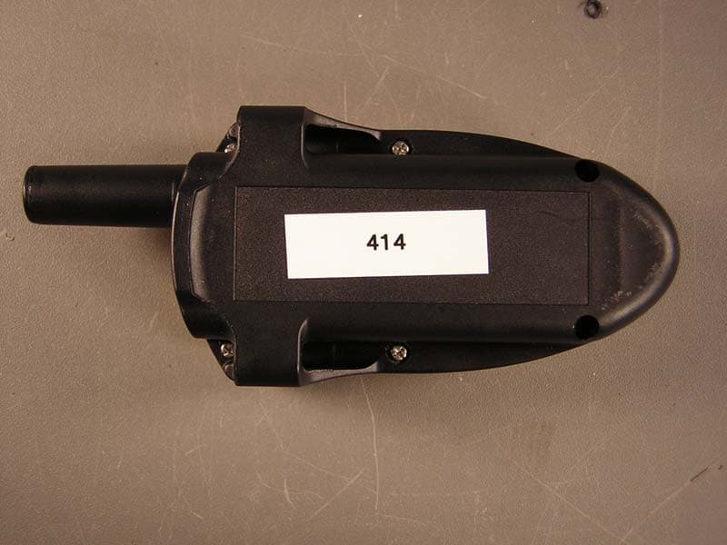
Click to zoom
Application Details
- Equipment Class
- DSR - Part 15 Remote Control/Security Device Transceiver
- Date of Grant
- Feb 26, 2007
- Application Purpose
- Original Equipment
- Date of Application
- Feb 25, 2007
- Equipment Note
- Safety Fob
- Frequency Range
- 433.90000000 - 433.90000000
- Company
- Garmin Canada Inc.
- Country
- Canada
Documents & Files
Document Text
Text extracted from the exhibit documents filed with the FCC. Open a document above to read the original.
Users Manual
COPYRIGHT© 2007 Premier GPS Inc. www.safetytrack.ca IS-FOB USER’S MANUAL COPYRIGHT© 2007 Premier GPS Inc. www.safetytrack.ca FCC Statement This device complies with Part 15 of the FCC Rules. Operation is subject to the following two conditions: (1) this device may not cause harmful interference, and (2) this device must accept any interference received, including interference that may cause undesired operation. This product contains no user serviceable parts. Changes or modifications not expressly approved by Dynastream Innovations Inc. could void the user’s authority to operate the equipment. COPYRIGHT© 2007 Premier GPS Inc. www.safetytrack.ca INTRODUCTION The IS-FOB is an advanced transceiver designed to assist workers to send signals through a vehicle (Relay) to a backend server located far away. It is equipped with a built-in buzzer, beeper and led to indicate various messages to the user. It can also receive acknowledgements from a server to indicate to the user that his message has been received. OPERATION Battery Installation: Obtain a fresh Duracell MN2400 AAA alkaline battery only. Using a coin, open the battery cover and install the battery. The negative or ‘flat’ side of the battery points up. Carefully replace the battery cover and hand tighten it with the coin. The battery lasts for about 30 days and when it gets ‘low’, the IS- FOB will beep 3 times every minute to indicate to the user that he needs to change the battery. 1. Turning the IS-FOB on or off: Push and hold the small button on the front of the IS-FOB. After 2 seconds, the IS-FOB will send a beep and will buzz as well as flash the LED to indicate to the user that the IS-FOB is now turned on. When the IS-FOB is turned on, the user needs to push the button 5 times within 5 seconds to turn it off. The IS-FOB will then emit a beep and power itself down. 2. Automatic Range Check: The IS-FOB will check to see if it is within range every six seconds. The LED will blink once every 6 seconds if the IS-FOB is within the relay range. If the IS-FOB is not within relay range, then the IS-FOB will beep once every six seconds indicating that it is out of relay range. 3. On-Demand Range Check: Pushing and releasing the button once causes the IS-FOB to request a local range check. The IS-FOB will respond with a single beep and buzz to indicate to the user that he is within relay range. 4. System Integrity Check: If the user pushes the button twice, the IS-FOB will request a full system check from the relay. The IS-FOB will emit 2 beeps/buzzes when it receives the acknowledgement from the server 5. Panic Alarm: If the user pushes and holds the button for over 3 seconds, the IS-FOB will send a panic alarm and will beep/buzz continuously until it receives an acknowledgement back from the server COPYRIGHT© 2007 Premier GPS Inc. www.safetytrack.ca • Note: The symbol means "CAUTION - RISK OF DANGER. CONSULT OPERATION MANUAL". • Warning: Contains no user serviceable components. Substitution of components may impair intrinsic safety. • Warning: To prevent ignition of flammable or combustible atmospheres, remove or replace the battery only in an area known to be free of combustible gases. • Notez : le symbole signifie "PRUDENCE - RISQUE DE DANGER. CONSULTEZ LE MANUEL D'OPÉRATION". • Avertissement : Ne contient aucunes composantes qui peut être servit par l’utilisateur. La substitution de composantes peut diminuer la sécurité intrinsèque. • Avertissement : Pour prévenir l'ignition d'atmosphères inflammables ou combustibles, enlevez ou remplacez la batterie seulement dans une région connue pour être libre des gaz combustibles. Electrical classification and Certification: Intrinsically Safe / Securite Intrinsique Exia UL 913 / CSA 22.2 No.157 Class I; Division 1; Groups C & D Hazardous Locations Temperature Code: T4 Voltage: 1.5 VDC Battery Type: Duracell MN2400
Cover Letter(s)
The purpose of the unit: The safety monitor fob is used in a system consisting of the fob, a relay station, and a monitoring base. The fob internally monitors the wearer's activity and if it detects that the wearer has stopped moving, it alerts first the wearer and then the monitoring base (via the relay station) that the wearer is somehow incapacitated. The wearer can also signal an emergency manually by pressing and holding the button on the fob. The intended application is to give workers an automated emergency alerting capability when they are working alone in oilfield or other industrial operations settings.
External Photos
REPORT: EG1431-1 FCC ID: O6RISFOBAA EXHIBIT: External Photos MODEL: ISFOBAA _____________________________________________________________ _____________________________________________________________ Curtis-Straus LLC • 527 Great Road • Littleton, MA • TEL (978) 486-8880 • FAX (978) 486-8828 Page 1 of 1
Internal Photos
REPORT: EG1431-1 FCC ID: O6RISFOBAA EXHIBIT: Internal Photos MODEL: ISFOBAA _____________________________________________________________ _____________________________________________________________ Curtis-Straus LLC • 527 Great Road • Littleton, MA • TEL (978) 486-8880 • FAX (978) 486-8828 Page 1 of 3 REPORT: EG1431-1 FCC ID: O6RISFOBAA EXHIBIT: Internal Photos MODEL: ISFOBAA _____________________________________________________________ _____________________________________________________________ Curtis-Straus LLC • 527 Great Road • Littleton, MA • TEL (978) 486-8880 • FAX (978) 486-8828 Page 2 of 3 REPORT: EG1431-1 FCC ID: O6RISFOBAA EXHIBIT: Internal Photos MODEL: ISFOBAA _____________________________________________________________ _____________________________________________________________ Curtis-Straus LLC • 527 Great Road • Littleton, MA • TEL (978) 486-8880 • FAX (978) 486-8828 Page 3 of 3
Test Report
Test Report Report No EG1431-1 Client Dynastream Innovations, Inc. 228 River Ave Cochrane, Alberta T4C 2C1 Phone 403-932-9292 FRN 0008033557 RSS-210 Issue 6; 47 CFR 15.231 Model ISFOBAA FCC ID O6RISFOBAA IC 3797A-ISFOBAA Equipment Type Low Power Communications Device Transmitter Equipment Code DXX Results As detailed within this report Prepared by _____________________ Evan Gould – Test Engineer Authorized by __________________________ Michael Buchholz – EMC Manager Issue Date 1/23/07 Conditions of issue This Test Report is issued subject to the conditions stated in ‘terms and conditions’ section of this report. Curtis-Straus LLC is accredited by the American Association for Laboratory Accreditation for the specific scope of accreditation under Certificate Number 1627-01. This report may contain data which is not covered by the A2LA accreditation. _____________________________________________________________ LLC • 527 Great Road • Littleton, MA • TEL (978) 486-8880 • FAX (978) 486-8828 Curtis-Straus REPORT: EG1431-1 FCC ID: O6RISFOBAA IC: 3797A-ISFOBAA _____________________________________________________________ _____________________________________________________________ Table Of Contents Summary.........................................................................................................................3 Test Methodology............................................................................................................3 Statement of Conformity..................................................................................................4 EUT Configuration...........................................................................................................5 Fundamental Measurement............................................................................................6 Radiated Spurious Emissions.........................................................................................7 Bandwidth.......................................................................................................................8 Duty Cycle.......................................................................................................................9 Test Equipment Used....................................................................................................10 LLC • 527 Great Road • Littleton, MA • TEL (978) 486-8880 • FAX (978) 486-8828 Page 2 of 15 Curtis-Straus REPORT: EG1431-1 FCC ID: O6RISFOBAA IC: 3797A-ISFOBAA _____________________________________________________________ _____________________________________________________________ Summary This test report supports an application for certification of a transmitter operating pursuant to 47 CFR 15.231 and RSS-210(Annex 1). The product is the Dynastream Innovations Safety Monitor Fob (Model: ISFOBAA). It is a transmitter that operates at 433.92MHz. Test Methodology Radiated emissions testing is performed according to the procedures specified in ANSI C63.4 (2003) and RSS-GEN. Emissions were maximized by rotating the device around three orthogonal axes as well as varying the test antenna’s height and polarity. The standard voltage for the EUT is 1.5VDC. Fresh batteries were used throughout testing. The environmental conditions are shown below. Date Temperature Humidity 12/27/06 23.5°C 22% Frequency range investigated: 30MHz – 4.5GHz Measurement distance: 30MHz – 4.5GHz 3m LLC • 527 Great Road • Littleton, MA • TEL (978) 486-8880 • FAX (978) 486-8828 Page 3 of 15 Curtis-Straus REPORT: EG1431-1 FCC ID: O6RISFOBAA IC: 3797A-ISFOBAA _____________________________________________________________ _____________________________________________________________ Statement of Conformity The ISFOBAA has been found to conform to the following parts of 47 CFR and RSS 210 as detailed below: RSS-GEN RSS 210 Part 15 Comments 5.3 15.15(b) There are no controls accessible to the user that vary the output power. 5.2 15.19 The label is shown in the label exhibit. 7.1.5 15.21 Information to the user is shown in the instruction manual exhibit. 15.27 No special accessories are required for compliance. 7.1.4 15.203 The antenna for this device is hardwired to the PCB. 2.6 15.205 15.209 The fundamental is not in a Restricted band and the spurious and harmonic emissions in the Restricted bands comply with the general emission limits of 15.209. 7.2.2 15.207 EUT is battery powered. No line conducted emissions were taken. A1.1.1 15.231(a) EUT meets the operational specifications of a periodic transmitter as described in 15.231(a) A1.1.2(1) 15.231(b) The fundamental and spurious emissions meet the limits in 15.231(b) LLC • 527 Great Road • Littleton, MA • TEL (978) 486-8880 • FAX (978) 486-8828 Page 4 of 15 Curtis-Straus REPORT: EG1431-1 FCC ID: O6RISFOBAA IC: 3797A-ISFOBAA _____________________________________________________________ _____________________________________________________________ EUT Configuration EUT Configuration Work Order: G1431 Company: Dynastream Innovations, Inc. Company Address: 228 River Ave Cochrane, Alberta T4C 2C1 Contact: Curtis Stafford MNSN EUT: ISFOBAA414 (normal operation); 420 (CW mode) EUT Description: Safety Monitor Fob EUT Max Fre quency: 433.9MHz Support Equipment: MNSN None EUT Cables: QtyShielded?LengthFerrites None Unpopulated EUT Ports: QtyReason None Software / Operating Mode Description: ISFOBAA transmits a 3.25ms message every 6 seconds in normal operation. In an alarm condition the EUT transmits the same 3.25ms message every 250ms which is activated by pressing the button. A sample was also provided with a diagnostic CW Mode to measure the peak fundamental. LLC • 527 Great Road • Littleton, MA • TEL (978) 486-8880 • FAX (978) 486-8828 Page 5 of 15 Curtis-Straus REPORT: EG1431-1 FCC ID: O6RISFOBAA IC: 3797A-ISFOBAA _____________________________________________________________ _____________________________________________________________ Fundamental Measurement LIMIT Average: 10995.8μV/m = 80.…
Text truncated - open the document above for the full version.
Test Setup Photos
REPORT: EG1431-1 FCC ID: O6RISFOBAA EXHIBIT: Setup Photo MODEL: ISFOBAA _____________________________________________________________ _____________________________________________________________ Curtis-Straus LLC • 527 Great Road • Littleton, MA • TEL (978) 486-8880 • FAX (978) 486-8828 Page 1 of 1
Contact Information
Applicant
Jim Rooney(President)
Test Firm
BUREAU VERITAS CONSUMER PRODUCTS SERVICES, INC.Ozgur Ozturk
[email protected]978-486-8880
Technical Specifications
| # | Rule Parts | Frequency Range | Power Output |
|---|---|---|---|
| 1 | 15.231 | 433.9 MHz - 433.9 MHz | - |
Other Applications from Garmin Canada Inc.
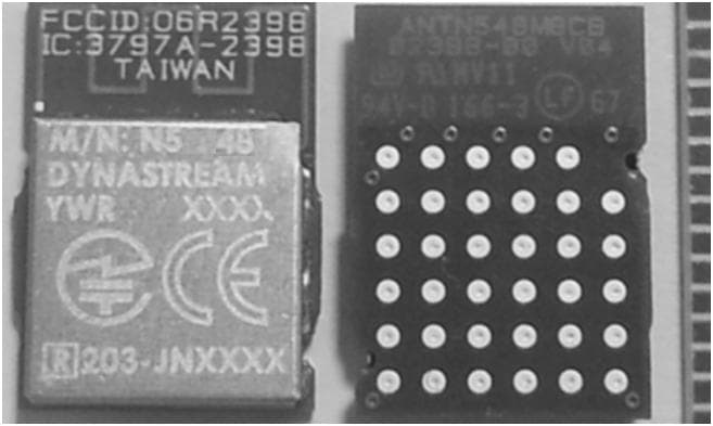
O6R2398
Mar 04, 2014N5
Equipment Class
DXX - Part 15 Low Power Communication Device Transmitter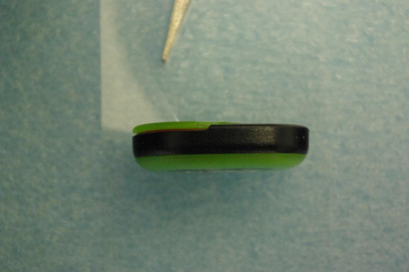
O6R02162
Jun 19, 2013LOW POWER TRANSMITTER (2400-2483.5)
Equipment Class
DXX - Part 15 Low Power Communication Device Transmitter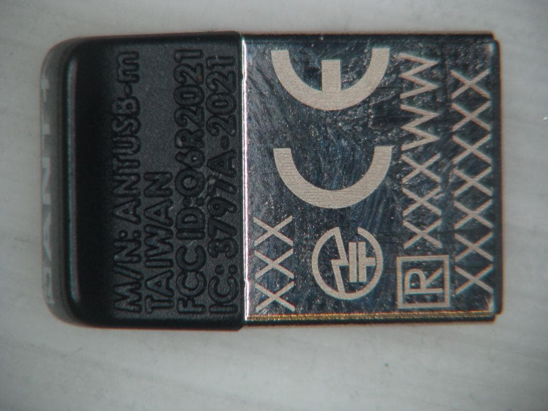
O6R2021
Jan 08, 2013LOW POWER TRANSMITTER (2400-2483.5 MHz)
Equipment Class
DXX - Part 15 Low Power Communication Device Transmitter
O6R1823
Sep 20, 2011LOW POWER TRANSMITTER (2400-2483.5 MHz)
Equipment Class
DXX - Part 15 Low Power Communication Device Transmitter
O6R01715
Jun 26, 2011LOW POWER TRANSMITTER (2400-2483.5 MHz)
Equipment Class
DXX - Part 15 Low Power Communication Device Transmitter