O6RM6R4NSpeed distance sensor
Garmin Canada Inc.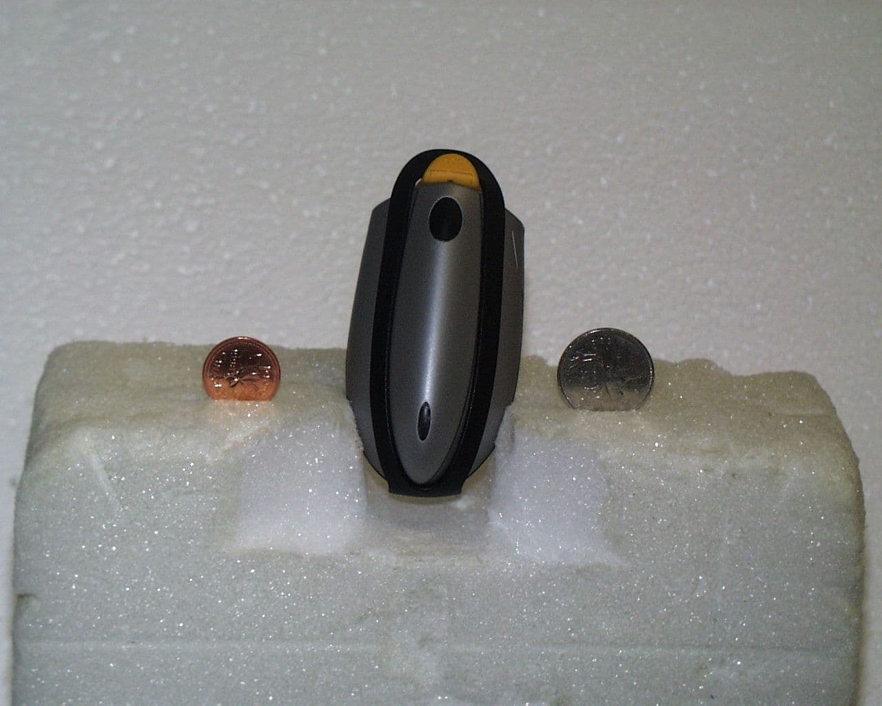
Click to zoom
Application Details
- Equipment Class
- DXX - Part 15 Low Power Communication Device Transmitter
- Date of Grant
- Nov 14, 2000
- Application Purpose
- Original Equipment
- Date of Application
- Sep 20, 2000
- Equipment Note
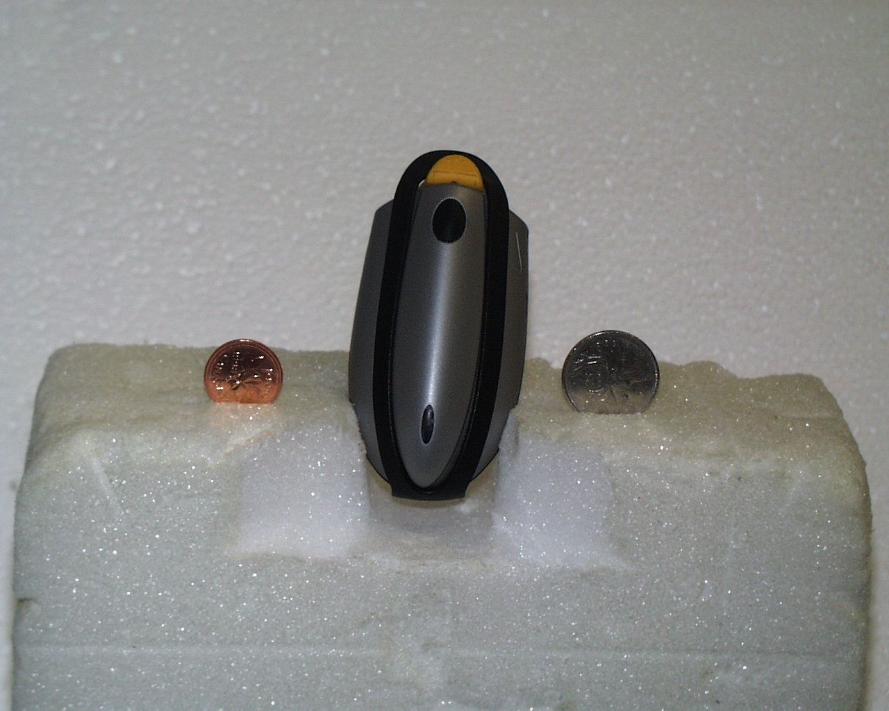
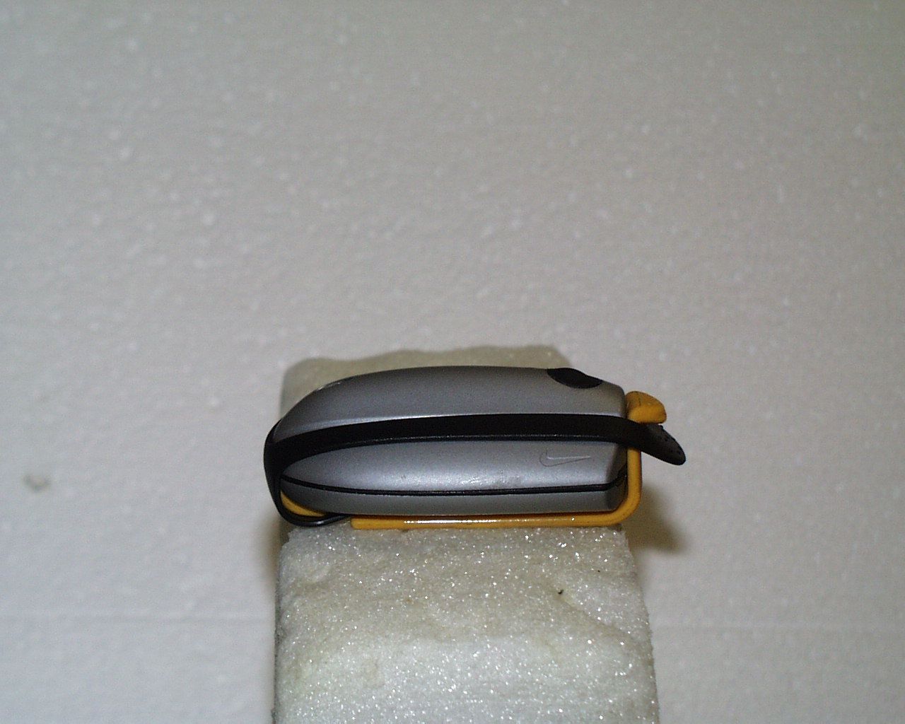
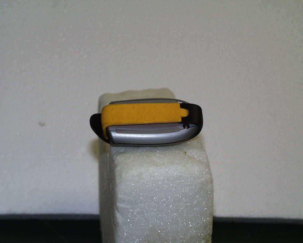
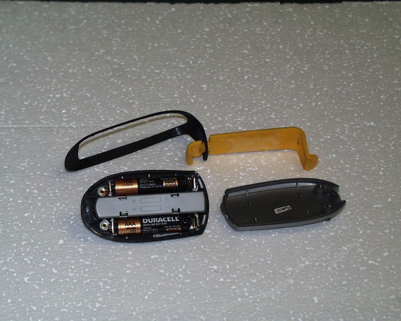
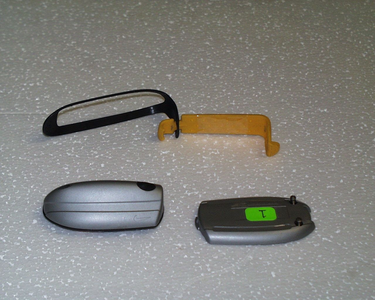
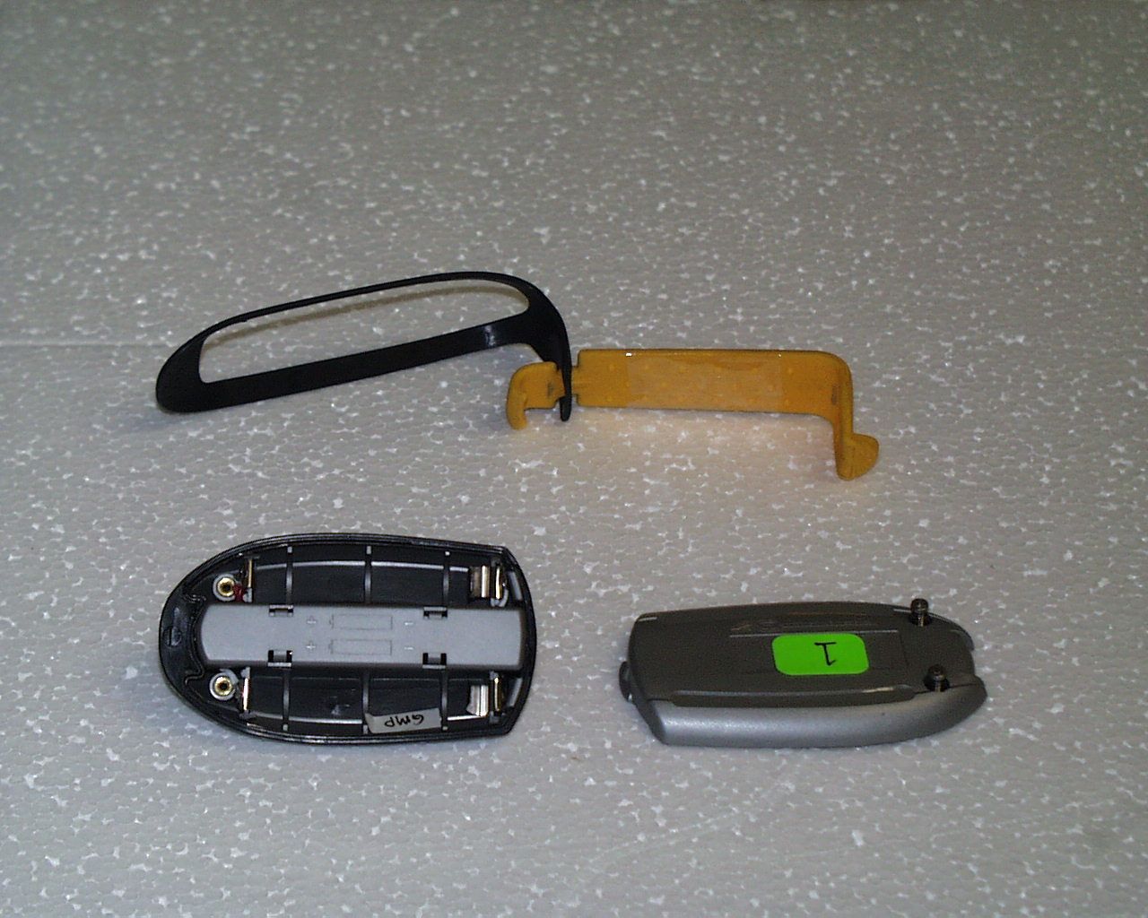
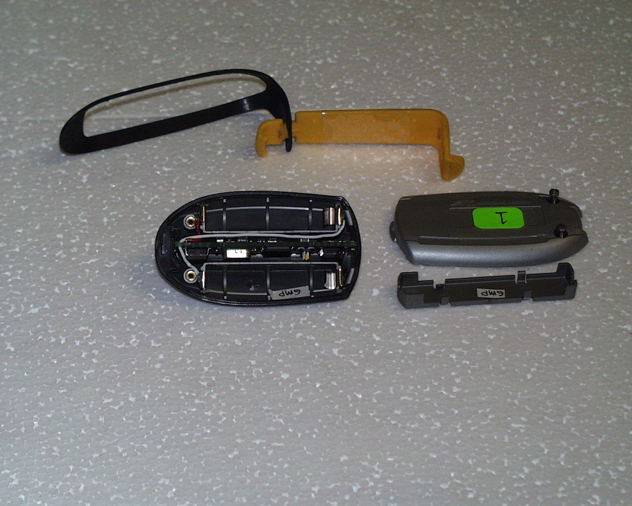
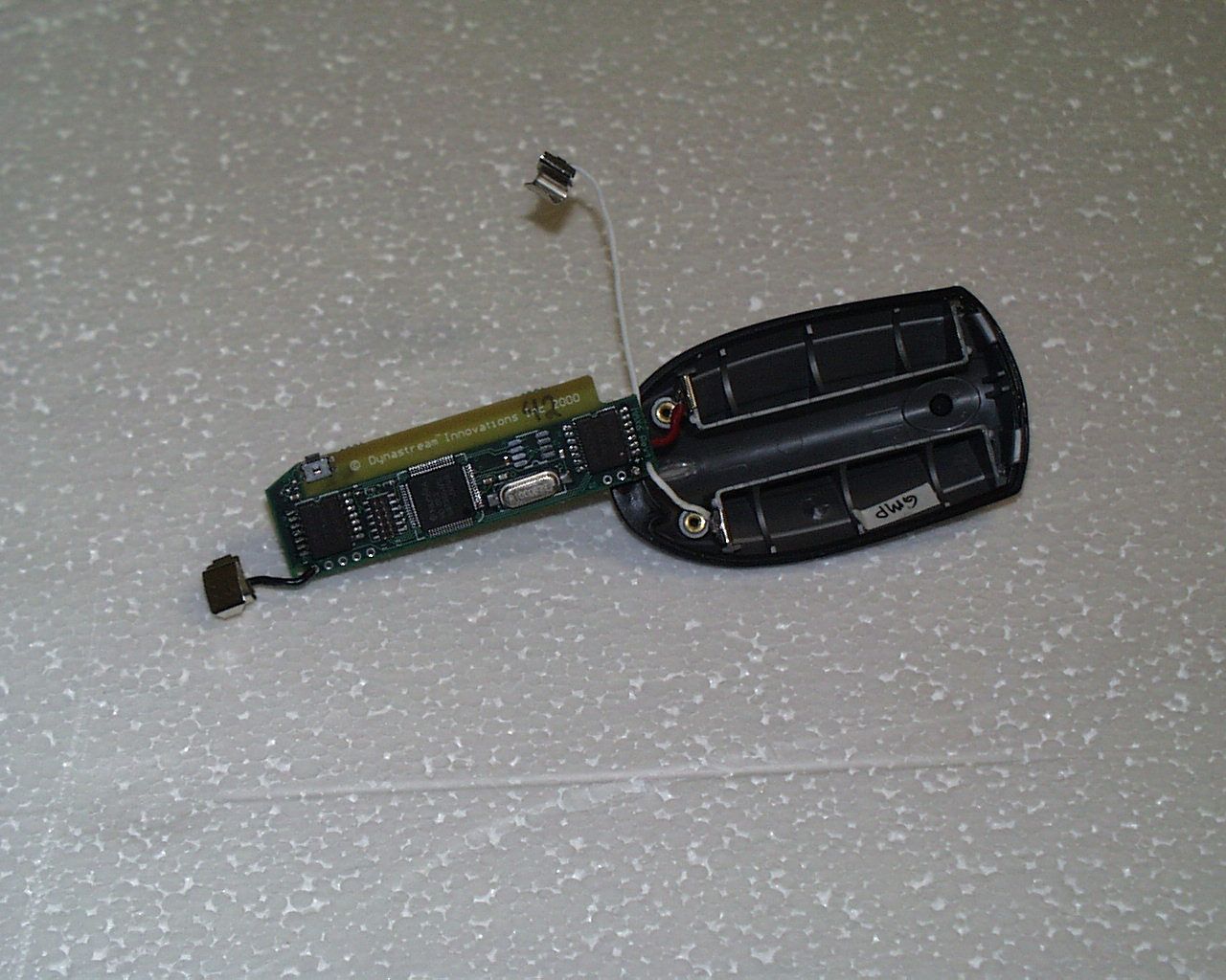
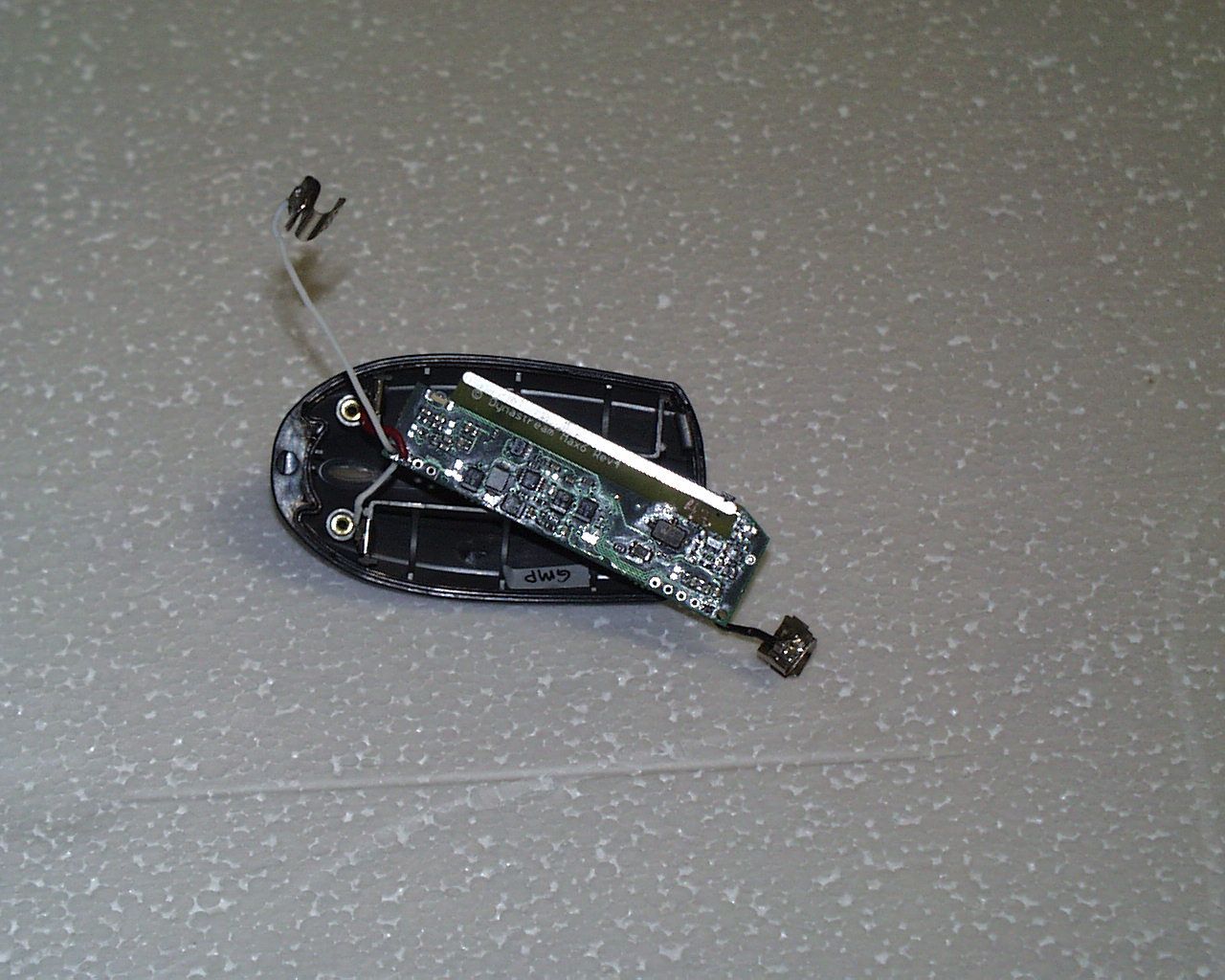
- Speed distance sensor
- Frequency Range
- 916.50000000 - 916.50000000
- Company
- Garmin Canada Inc.
- Country
- Canada
Documents & Files
Document Text
Text extracted from the exhibit documents filed with the FCC. Open a document above to read the original.
Users Manual
1 INSTRUCTIONS 1 SDM TRIAX 100 © 2000 Nike, Inc. All rights reserved.Dynastream is a trademark of Dynastream Innovations Inc. This device complies with part 15 of the FCC Rules. Operation is subject to the followingtwo conditions: (1) This device may not cause harmful interference, and (2) this device mustaccept any interference that may cause undesired operation. 9328.2- SDM-ENG 6/13/00 5:51 PM Page 1 2 3 CONTENTS Information is power . Your SDM Triax 100 watch is designed to tell you how fast and how far youhave run, and provide quick, one-touch access to a variety of criticalinformation during training and in competition. Nike Techlab is proud to be the first to provide athletes with this revolu-tionary new training tool. Never before has the technology been sufficientfor a runner to accurately determine their pace and distance. Using anultra-modern accelerometer technology combined with an RF (RadioFrequency) transceiver, the SDM Triax 100 can provide speed and distanceinformation to runners that is more than 97% accurate. This manual combines step-by-step operational instructions to help youidentify the programmable features and functions of each specific mode. Itis not the goal of this manual to provide all of the information necessary toembark upon a training regimen. There are numerous books on the subject,good information on the Internet, and professional trainers affiliated withmost health clubs. Remember, this speed and distance monitor is just onepart of an intelligent exercise plan. Before beginning any exercise regimen, you should consult your physicianor health professional. There are numerous factors to consider whendetermining your pace limits and exercise intensity level. Some of thesefactors include your age, the frequency with which you exercise and youroverall physical fitness. Throughout this manual, look for the symbol to identify especiallyuseful and important information. s GETTING STARTED 4 THE SPEED SENSOR 6 OPERATING INSTRUCTIONS MODES 9 MAKING ADJUSTMENTS TO MODE SETTINGS 10 TIME 11 RUN 12 GRAPH 14 CHRONOGRAPH 15 DATA 17 TIMER 18 ALARM 19 NIKE ELECTROLITE 20 SPECIFICATIONS 21 WARRANTY 21 REPAIR CENTERS 44 9328.2- SDM-ENG 6/13/00 5:51 PM Page 2 5 4 We’ve tried to make this watch as easy as possible to use. Great care hasbeen taken to make the button functions consistent and clear. Even if youdon’t read the whole manual, you should be able to work your watch if youunderstand, in general, how the buttons work.BUTTON FUNCTIONS, LEFT SIDEADJUST/EXITThink of ADJUST/EXIT as the button to use when you want to adjust, set orreset something. For example, if you want to adjust the time, or reset thechronograph. This button is a little different than the other buttonsbecause you usually have to press and hold it for a few seconds. This is soyou don’t accidentally reset or adjust something. MODE/NEXTThe MODE/NEXT button will normally move you to the next mode. Whenyou are making adjustments or setting something, the MODE/NEXT buttonwill move you to the next adjustable element. GETTING STARTED BUTTON FUNCTIONS, RIGHT SIDE The buttons on the right hand side of the watch have more functions thanthe buttons on the left side. For that reason, we’ve included all the detailsfor quick reference. START/LAP You can think of the START/LAP button as the “go,” “plus,” or “moveforward” button. It also functions as an on/off switch in some modes. • In TIME mode, press to turn the chime on and off. • In CHRON mode, press to start the chronograph and mark lap completion. • In TIMER mode, press to start the countdown timer.• In GRAPH mode, press to move forward through the list of data points. • In DATA mode, press to move forward through the list of data points.• In ALARM mode, press to turn the alarm on and off. • When making adjustments, press to advance the blinking element. STOPThe STOP button is the opposite of the START/LAP button. Think of it as the“stop,” “minus,” or “go backwards” button. This button will also allow youto alternate selections in some modes. • In TIME mode, press and hold to select time zone 1 or 2.• In CHRON mode, press to stop the chronograph and save run data to memory. • In TIMER mode, press to stop the countdown timer.• In ALARM mode, press to select alarm 1 or 2.• In DATA mode, press to select run number. • When making adjustments, press to reverse the blinking element. ELECTROLITE BUTTONThe ELECTROLITE button is used to turn on the light. If you press and hold the ELECTROLITE button, you can make the light comeon at the press of any button. It’s great for night use. We call it auto-Electrolite. S T A R T / L A P A D J U S T / E X I T M O D E / N E X T S T O P H20 RESIST 100M STOP START/LAP MODE/NEXT ADJUST/EXIT ELECTROLITE 9328.2- SDM-ENG 6/13/00 5:51 PM Page 4 You can attach the speed sensor to either sneaker. It is important to beconsistent in how you attach it. Make sure it is attached it to the lacessecurely enough that there is no “wobble” when you are running. Finally,it should be aligned with the foot and secured well enough that thealignment does not change during a run. 1. Lace the speed sensor clip into your sneakers before you attach the speed sensor itself. 2. Then attach the speed sensor to the clip as shown. DIRECTIONS FOR NORMAL USEFollow these instructions for normal use of thespeed sensor. The speed sensor is equipped with a powerbutton. When not in use, store the speed sensorwith the power off to conserve battery life.TURN POWER ONPress the power button. A light will indicatethat the speed sensor is activated. The watchwill begin linking when it receives a signalfrom the speed sensor. When running orwalking, your speed and distance informationis automatically transmitted to your watch.TURN POWER OFFPress and hold the power button. The light willturn off, indicating that the power is off. 7 ATTACHING THE SPEED SENSOR TO YOUR SNEAKER Attach sensor to clip as shown. 6 The core of the SDM Triax 100 watch technology is housed in a speedsensor, …
Text truncated - open the document above for the full version.
Attestation Statements
Receiver Declaration of Conformity 21 st Sept 2000 Receiver declaration of conformity is in process and is to be attached when available.
ID Label/Location Info
1 INSTRUCTIONS 1 SDM TRIAX 100 © 2000 Nike, Inc. All rights reserved.Dynastream is a trademark of Dynastream Innovations Inc. This device complies with part 15 of the FCC Rules. Operation is subject to the followingtwo conditions: (1) This device may not cause harmful interference, and (2) this device mustaccept any interference that may cause undesired operation. 9328.2- SDM-ENG 6/13/00 5:51 PM Page 1 2 3 CONTENTS Information is power . Your SDM Triax 100 watch is designed to tell you how fast and how far youhave run, and provide quick, one-touch access to a variety of criticalinformation during training and in competition. Nike Techlab is proud to be the first to provide athletes with this revolu-tionary new training tool. Never before has the technology been sufficientfor a runner to accurately determine their pace and distance. Using anultra-modern accelerometer technology combined with an RF (RadioFrequency) transceiver, the SDM Triax 100 can provide speed and distanceinformation to runners that is more than 97% accurate. This manual combines step-by-step operational instructions to help youidentify the programmable features and functions of each specific mode. Itis not the goal of this manual to provide all of the information necessary toembark upon a training regimen. There are numerous books on the subject,good information on the Internet, and professional trainers affiliated withmost health clubs. Remember, this speed and distance monitor is just onepart of an intelligent exercise plan. Before beginning any exercise regimen, you should consult your physicianor health professional. There are numerous factors to consider whendetermining your pace limits and exercise intensity level. Some of thesefactors include your age, the frequency with which you exercise and youroverall physical fitness. Throughout this manual, look for the symbol to identify especiallyuseful and important information. s GETTING STARTED 4 THE SPEED SENSOR 6 OPERATING INSTRUCTIONS MODES 9 MAKING ADJUSTMENTS TO MODE SETTINGS 10 TIME 11 RUN 12 GRAPH 14 CHRONOGRAPH 15 DATA 17 TIMER 18 ALARM 19 NIKE ELECTROLITE 20 SPECIFICATIONS 21 WARRANTY 21 REPAIR CENTERS 44 9328.2- SDM-ENG 6/13/00 5:51 PM Page 2 5 4 We’ve tried to make this watch as easy as possible to use. Great care hasbeen taken to make the button functions consistent and clear. Even if youdon’t read the whole manual, you should be able to work your watch if youunderstand, in general, how the buttons work.BUTTON FUNCTIONS, LEFT SIDEADJUST/EXITThink of ADJUST/EXIT as the button to use when you want to adjust, set orreset something. For example, if you want to adjust the time, or reset thechronograph. This button is a little different than the other buttonsbecause you usually have to press and hold it for a few seconds. This is soyou don’t accidentally reset or adjust something. MODE/NEXTThe MODE/NEXT button will normally move you to the next mode. Whenyou are making adjustments or setting something, the MODE/NEXT buttonwill move you to the next adjustable element. GETTING STARTED BUTTON FUNCTIONS, RIGHT SIDE The buttons on the right hand side of the watch have more functions thanthe buttons on the left side. For that reason, we’ve included all the detailsfor quick reference. START/LAP You can think of the START/LAP button as the “go,” “plus,” or “moveforward” button. It also functions as an on/off switch in some modes. • In TIME mode, press to turn the chime on and off. • In CHRON mode, press to start the chronograph and mark lap completion. • In TIMER mode, press to start the countdown timer.• In GRAPH mode, press to move forward through the list of data points. • In DATA mode, press to move forward through the list of data points.• In ALARM mode, press to turn the alarm on and off. • When making adjustments, press to advance the blinking element. STOPThe STOP button is the opposite of the START/LAP button. Think of it as the“stop,” “minus,” or “go backwards” button. This button will also allow youto alternate selections in some modes. • In TIME mode, press and hold to select time zone 1 or 2.• In CHRON mode, press to stop the chronograph and save run data to memory. • In TIMER mode, press to stop the countdown timer.• In ALARM mode, press to select alarm 1 or 2.• In DATA mode, press to select run number. • When making adjustments, press to reverse the blinking element. ELECTROLITE BUTTONThe ELECTROLITE button is used to turn on the light. If you press and hold the ELECTROLITE button, you can make the light comeon at the press of any button. It’s great for night use. We call it auto-Electrolite. S T A R T / L A P A D J U S T / E X I T M O D E / N E X T S T O P H20 RESIST 100M STOP START/LAP MODE/NEXT ADJUST/EXIT ELECTROLITE 9328.2- SDM-ENG 6/13/00 5:51 PM Page 4 You can attach the speed sensor to either sneaker. It is important to beconsistent in how you attach it. Make sure it is attached it to the lacessecurely enough that there is no “wobble” when you are running. Finally,it should be aligned with the foot and secured well enough that thealignment does not change during a run. 1. Lace the speed sensor clip into your sneakers before you attach the speed sensor itself. 2. Then attach the speed sensor to the clip as shown. DIRECTIONS FOR NORMAL USEFollow these instructions for normal use of thespeed sensor. The speed sensor is equipped with a powerbutton. When not in use, store the speed sensorwith the power off to conserve battery life.TURN POWER ONPress the power button. A light will indicatethat the speed sensor is activated. The watchwill begin linking when it receives a signalfrom the speed sensor. When running orwalking, your speed and distance informationis automatically transmitted to your watch.TURN POWER OFFPress and hold the power button. The light willturn off, indicating that the power is off. 7 ATTACHING THE SPEED SENSOR TO YOUR SNEAKER Attach sensor to clip as shown. 6 The core of the SDM Triax 100 watch technology is housed in a speedsensor, …
Text truncated - open the document above for the full version.
Test Report
M36r2334 MPB Technologies Inc. 319 This report shall not be reproduced, except in full, without prior written approval of MPB Technologies Inc. ISO/IECGuide25: 1990 Test Report Prepared By: Electronics Test Centre MPB Technologies Inc. Unit 100 302 Legget Drive Kanata Ontario K2K 1Y5 TEST REPORT ON Dynastream Speed Sensor Model: sdm-triax100 Foot Piece (Transmitter) IN ACCORDANCE WITH FCC Pt 15 Subpart C 1996 And IC RSS-210 1998 MPBT Report No.: M36R2334Customer No.: 1176 Test Personnel: D. Zanette Prepared for: _________________________ Client Acceptance Authorized Signatory Murandi Communications Ltd 240, 6715 – 8 Street NE Calgary, Alberta Canada T2E 7H7 ________________________ _ Dan Zanette Lab Supervisor Electromagnetic Services IC . 3201-1 Electromagnetics Division Authorized Signatory Sept-14-2000 Test Sample: DynaStream Speed Sensor Model: sdm- triax100 Report No.: M36R2334 M36r2334 MPB Technologies Inc. Page 2 of 35 This report shall not be reproduced, except in full, without prior written approval of MPB Technologies Inc. ________________________ _ Reviewed By Test Sample: DynaStream Speed Sensor Model: sdm- triax100 Report No.: M36R2334 M36r2334 MPB Technologies Inc. Page 3 of 35 This report shall not be reproduced, except in full, without prior written approval of MPB Technologies Inc. TABLE OF CONTENTS 1.0INTRODUCTION 1.1SCOPE 1.2APPLICANT 1.3APPLICABILITY 1.4TEST SAMPLE DESCRIPTION 1.5GENERAL TEST CONDITIONS AND ASSUMPTIONS 1.6SCOPE OF TESTING 1.6.1VARIATIONS IN TEST METHODS 1.6.2TEST SAMPLE MODIFICATIONS 2.0TEST CONCLUSION 2.1CONDUCTED EMISSIONS N OT A PPLICABLE 2.1.1CONDUCTED EMISSIONS DATA 2.1.2CONDUCTED EMISSIONS PHOTO 2.2RADIATED EMISSIONS 2.2.1RADIATED EMISSIONS DATA 2.2.2RADIATED EMISSIONS PHOTO 3.0TEST FACILITY 3.1LOCATION 3.2GROUNDING PLAN 3.3POWER 3.4EMISSIONS PROFILE 3.5TEST CONFIGURATION 3.5.1TYPICAL TEST SETUP 4.0TEST EQUIPMENT 4.1RADIATED EMISSIONS 4.2CONDUCTED EMISSIONS ( N OT A PPLICABLE ) 4.3EMI SPECTRUM ANALYZER AND RECEIVER 4.3.1SPECTRUM ANALYZER 4.3.2RECEIVER Test Sample: DynaStream Speed Sensor Model: sdm- triax100 Report No.: M36R2334 M36r2334 MPB Technologies Inc. Page 4 of 35 This report shall not be reproduced, except in full, without prior written approval of MPB Technologies Inc. 1.0 INTRODUCTION 1.1SCOPE The purpose of this report is to present the findings and results of compliance testing performed, against FCC Part Subpart C, 15.249 1996 and IC RSS-210 , 1998. 1.2APPLICANT This test report has been prepared for Murandi Communications Ltd. 1.3APPLICABILIT Y All test procedures, limits, and results defined in this document apply to the Murandi Communications Ltd: Dynastream Speed Sensor Model: sdm-triax100 unit, which shall be referred to herein as the Equipment Under Test ( EUT ). The results contained in this report relate only to the item(s) tested. This report does not imply product endorsement by NVLAP or the Canadian or US governments. 1.4TEST SAMPLE DESCRIPTION The test sample, provided for testing was a Dynastream Speed Sensor Model: sdm-triax100 . Pre-production Unit.... Prototype...... Product Type: Low power transmitter Frequency: 916.5 MHz Frequency Stability: 120 PPM Serial Number: NA Output Power : 25 mV/m Nominal (0.00042W) Modulation: ASK 100% Modulation Depth (00K) Model Number: sdm-triax100 Cables: None Power Requirements: 2 AAA Duracell Batteries Peripheral Equipment: NA The EUT is designated as the “foot piece” which can be mounted on the laces of a shoe. The foot piece is an rf transmitter that computes the user’s speed and distance traveled by means of integrating the foot path, and passes the information to a watch display also carried by the user. This report is only applicable to the foot piece. Test Sample: DynaStream Speed Sensor Model: sdm- triax100 Report No.: M36R2334 M36r2334 MPB Technologies Inc. Page 5 of 35 This report shall not be reproduced, except in full, without prior written approval of MPB Technologies Inc. 24.0- . GENERAL TEST CONDITIONS AND ASSUMPTIONS The EUT was setup and exercised using the configurations, modes of operation and arrangements defined in this report only. All inputs and outputs to and from other equipment associated with the EUT were adequately simulated. Where relevant, the EUT was only tested using the monitoring methods and test criteria defined in this report. All testing, unless otherwise noted, was performed under the following environmental conditions: Temperature:17 to 23 ° C Humidity:45 to 75 % Barometric Pressure: 68 to 106 kPa 24.0- . SCOPE OF TESTING Tests were performed in accordance with ANSI 63.4 1992 24.0-24. VARIATIONS IN TEST METHODS There were no variations from the test procedures outlined above. 24.0-24. TEST SAMPLE MODIFICATIONS There were no equipment modifications during test performance. Test Sample: DynaStream Speed Sensor Model: sdm- triax100 Report No.: M36R2334 M36r2334 MPB Technologies Inc. Page 6 of 35 This report shall not be reproduced, except in full, without prior written approval of MPB Technologies Inc. 24.0- . TEST CONCLUSION The EUT was subjected to the following tests. Compliance is designated by a PASS or FAIL . The following table summarizes the test results and details the tests performed in terms of the specification and class or level applied, the unique test sample identification, and the EUT modification state, the mode of operation, configuration and cable arrangement (if applicable). Test Case Test TypeSpecificationClass/ Level Sample TestMod State ENG. / QUAL. Criteria Result 2.1Conducted Emissions FCC Part 15 Subpart C 1996 IC RSS-210 Issue 2, Rev 1, 1998 NANANANAN/A Not Applicable 2.2Radiated Emissions FCC Part 15 Subpart C 1996 IC RSS-210 Issue 2, Rev 1, 1998 A/BDynaStream Speed Sensor Model: sdm- triax100 NoneQualSec. Pass STATEMENT OF COMPLIANCE The client equipment referred to in this report was found to comply with the requirements as stated above. Test Sample: DynaStream Speed Sensor Model: sdm- triax100 Report No.: M36R23…
Text truncated - open the document above for the full version.
Test Report
M36r2334 MPB Technologies Inc. 319 This report shall not be reproduced, except in full, without prior written approval of MPB Technologies Inc. ISO/IECGuide25: 1990 Test Report Prepared By: Electronics Test Centre MPB Technologies Inc. Unit 100 302 Legget Drive Kanata Ontario K2K 1Y5 TEST REPORT ON Dynastream Speed Sensor Model: sdm-triax100 Foot Piece (Transmitter) IN ACCORDANCE WITH FCC Pt 15 Subpart C 1996 And IC RSS-210 1998 MPBT Report No.: M36R2334Customer No.: 1176 Test Personnel: D. Zanette Prepared for: _________________________ Client Acceptance Authorized Signatory Murandi Communications Ltd 240, 6715 – 8 Street NE Calgary, Alberta Canada T2E 7H7 ________________________ _ Dan Zanette Lab Supervisor Electromagnetic Services IC . 3201-1 Electromagnetics Division Authorized Signatory Sept-14-2000 Test Sample: DynaStream Speed Sensor Model: sdm- triax100 Report No.: M36R2334 M36r2334 MPB Technologies Inc. Page 2 of 35 This report shall not be reproduced, except in full, without prior written approval of MPB Technologies Inc. ________________________ _ Reviewed By Test Sample: DynaStream Speed Sensor Model: sdm- triax100 Report No.: M36R2334 M36r2334 MPB Technologies Inc. Page 3 of 35 This report shall not be reproduced, except in full, without prior written approval of MPB Technologies Inc. TABLE OF CONTENTS 1.0INTRODUCTION 1.1SCOPE 1.2APPLICANT 1.3APPLICABILITY 1.4TEST SAMPLE DESCRIPTION 1.5GENERAL TEST CONDITIONS AND ASSUMPTIONS 1.6SCOPE OF TESTING 1.6.1VARIATIONS IN TEST METHODS 1.6.2TEST SAMPLE MODIFICATIONS 2.0TEST CONCLUSION 2.1CONDUCTED EMISSIONS N OT A PPLICABLE 2.1.1CONDUCTED EMISSIONS DATA 2.1.2CONDUCTED EMISSIONS PHOTO 2.2RADIATED EMISSIONS 2.2.1RADIATED EMISSIONS DATA 2.2.2RADIATED EMISSIONS PHOTO 3.0TEST FACILITY 3.1LOCATION 3.2GROUNDING PLAN 3.3POWER 3.4EMISSIONS PROFILE 3.5TEST CONFIGURATION 3.5.1TYPICAL TEST SETUP 4.0TEST EQUIPMENT 4.1RADIATED EMISSIONS 4.2CONDUCTED EMISSIONS ( N OT A PPLICABLE ) 4.3EMI SPECTRUM ANALYZER AND RECEIVER 4.3.1SPECTRUM ANALYZER 4.3.2RECEIVER Test Sample: DynaStream Speed Sensor Model: sdm- triax100 Report No.: M36R2334 M36r2334 MPB Technologies Inc. Page 4 of 35 This report shall not be reproduced, except in full, without prior written approval of MPB Technologies Inc. 1.0 INTRODUCTION 1.1SCOPE The purpose of this report is to present the findings and results of compliance testing performed, against FCC Part Subpart C, 15.249 1996 and IC RSS-210 , 1998. 1.2APPLICANT This test report has been prepared for Murandi Communications Ltd. 1.3APPLICABILIT Y All test procedures, limits, and results defined in this document apply to the Murandi Communications Ltd: Dynastream Speed Sensor Model: sdm-triax100 unit, which shall be referred to herein as the Equipment Under Test ( EUT ). The results contained in this report relate only to the item(s) tested. This report does not imply product endorsement by NVLAP or the Canadian or US governments. 1.4TEST SAMPLE DESCRIPTION The test sample, provided for testing was a Dynastream Speed Sensor Model: sdm-triax100 . Pre-production Unit.... Prototype...... Product Type: Low power transmitter Frequency: 916.5 MHz Frequency Stability: 120 PPM Serial Number: NA Output Power : 25 mV/m Nominal (0.00042W) Modulation: ASK 100% Modulation Depth (00K) Model Number: sdm-triax100 Cables: None Power Requirements: 2 AAA Duracell Batteries Peripheral Equipment: NA The EUT is designated as the “foot piece” which can be mounted on the laces of a shoe. The foot piece is an rf transmitter that computes the user’s speed and distance traveled by means of integrating the foot path, and passes the information to a watch display also carried by the user. This report is only applicable to the foot piece. Test Sample: DynaStream Speed Sensor Model: sdm- triax100 Report No.: M36R2334 M36r2334 MPB Technologies Inc. Page 5 of 35 This report shall not be reproduced, except in full, without prior written approval of MPB Technologies Inc. 24.0- . GENERAL TEST CONDITIONS AND ASSUMPTIONS The EUT was setup and exercised using the configurations, modes of operation and arrangements defined in this report only. All inputs and outputs to and from other equipment associated with the EUT were adequately simulated. Where relevant, the EUT was only tested using the monitoring methods and test criteria defined in this report. All testing, unless otherwise noted, was performed under the following environmental conditions: Temperature:17 to 23 ° C Humidity:45 to 75 % Barometric Pressure: 68 to 106 kPa 24.0- . SCOPE OF TESTING Tests were performed in accordance with ANSI 63.4 1992 24.0-24. VARIATIONS IN TEST METHODS There were no variations from the test procedures outlined above. 24.0-24. TEST SAMPLE MODIFICATIONS There were no equipment modifications during test performance. Test Sample: DynaStream Speed Sensor Model: sdm- triax100 Report No.: M36R2334 M36r2334 MPB Technologies Inc. Page 6 of 35 This report shall not be reproduced, except in full, without prior written approval of MPB Technologies Inc. 24.0- . TEST CONCLUSION The EUT was subjected to the following tests. Compliance is designated by a PASS or FAIL . The following table summarizes the test results and details the tests performed in terms of the specification and class or level applied, the unique test sample identification, and the EUT modification state, the mode of operation, configuration and cable arrangement (if applicable). Test Case Test TypeSpecificationClass/ Level Sample TestMod State ENG. / QUAL. Criteria Result 2.1Conducted Emissions FCC Part 15 Subpart C 1996 IC RSS-210 Issue 2, Rev 1, 1998 NANANANAN/A Not Applicable 2.2Radiated Emissions FCC Part 15 Subpart C 1996 IC RSS-210 Issue 2, Rev 1, 1998 A/BDynaStream Speed Sensor Model: sdm- triax100 NoneQualSec. Pass STATEMENT OF COMPLIANCE The client equipment referred to in this report was found to comply with the requirements as stated above. Test Sample: DynaStream Speed Sensor Model: sdm- triax100 Report No.: M36R23…
Text truncated - open the document above for the full version.
Contact Information
Applicant
Jim Rooney(President)
Technical Contact
MPB Technologieswilliam waterhouse
[email protected]613-599-6800
301 Legget Drive, Unit 100 · Kanata, Ontario · Canada
Test Firm
MPB Technologies Inc.Daniele Zanette
Technical Specifications
| # | Rule Parts | Frequency Range | Power Output | Tolerance |
|---|---|---|---|---|
| 1 | 15C | 916.5 MHz - 916.5 MHz | - | ppm |
Other Applications from Garmin Canada Inc.
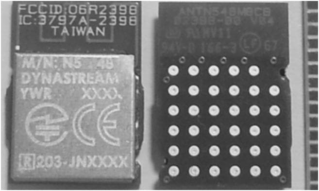
O6R2398
Mar 04, 2014N5
Equipment Class
DXX - Part 15 Low Power Communication Device Transmitter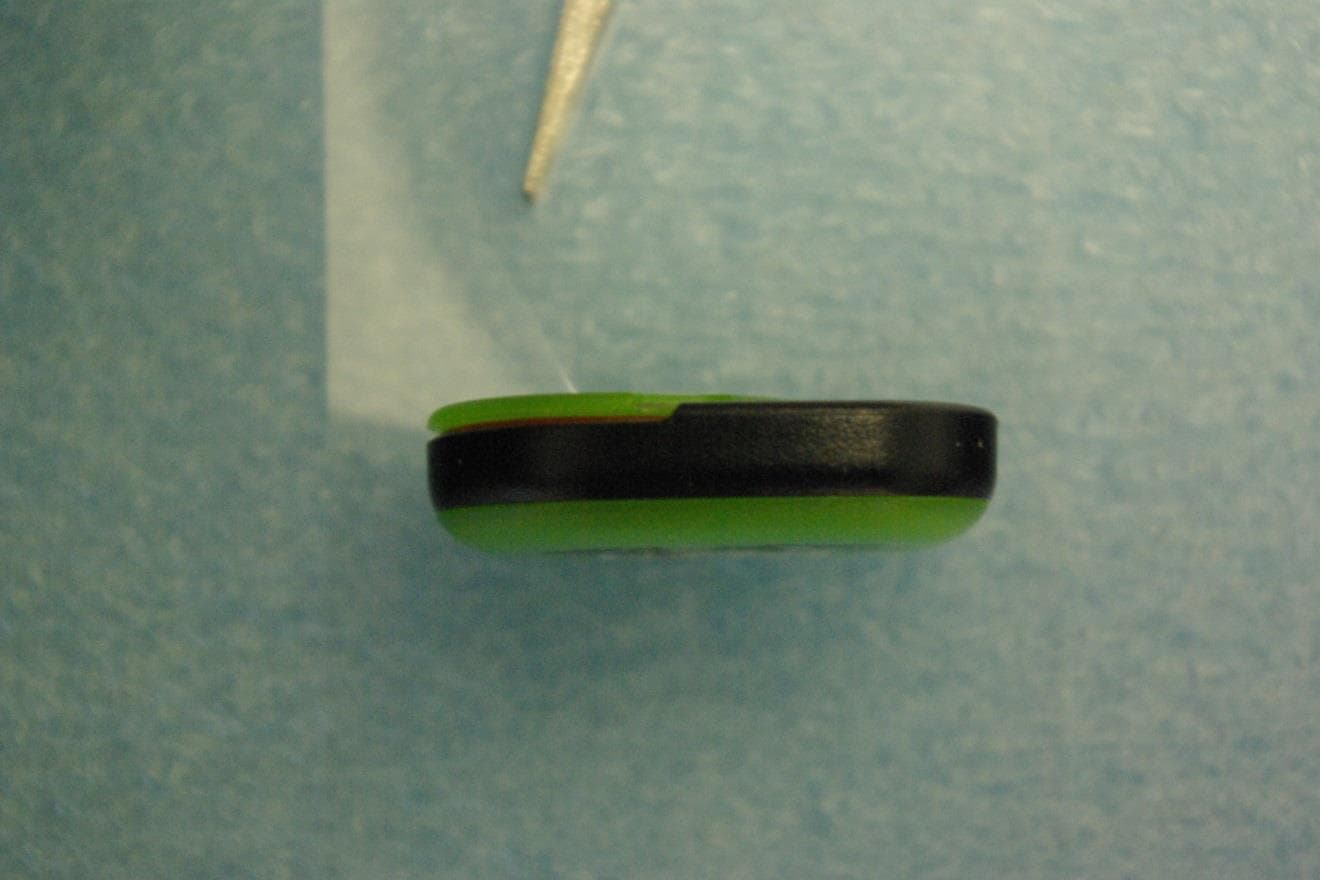
O6R02162
Jun 19, 2013LOW POWER TRANSMITTER (2400-2483.5)
Equipment Class
DXX - Part 15 Low Power Communication Device Transmitter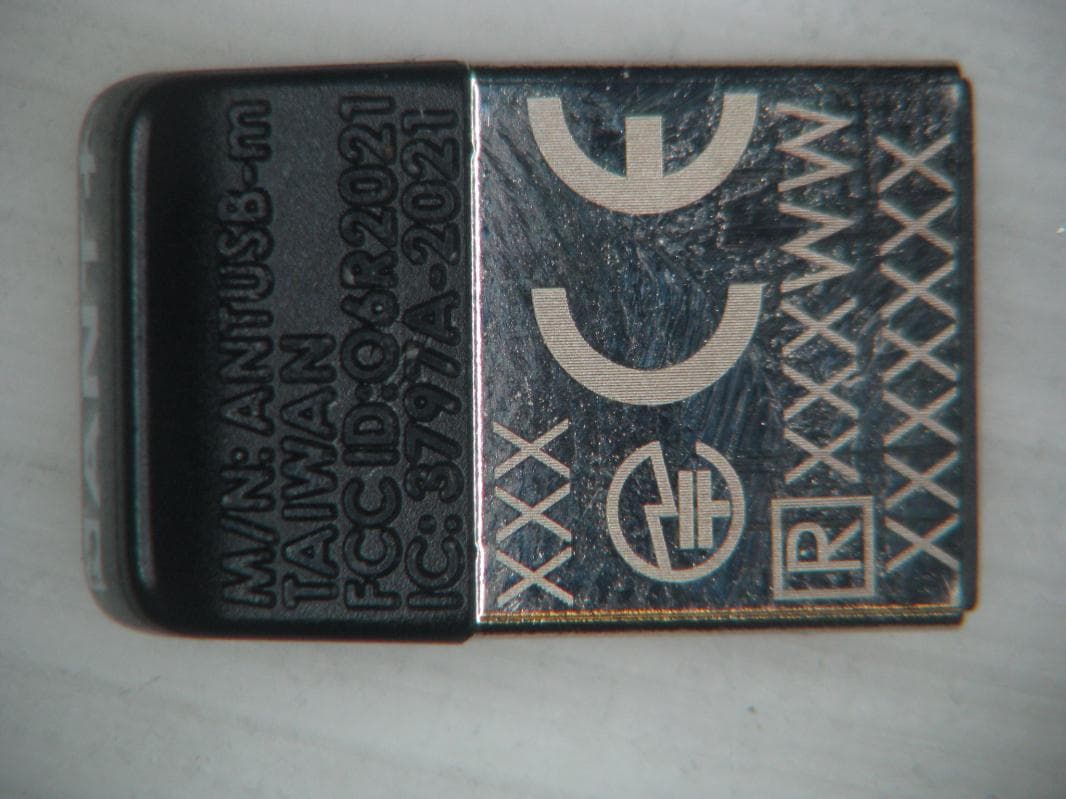
O6R2021
Jan 08, 2013LOW POWER TRANSMITTER (2400-2483.5 MHz)
Equipment Class
DXX - Part 15 Low Power Communication Device Transmitter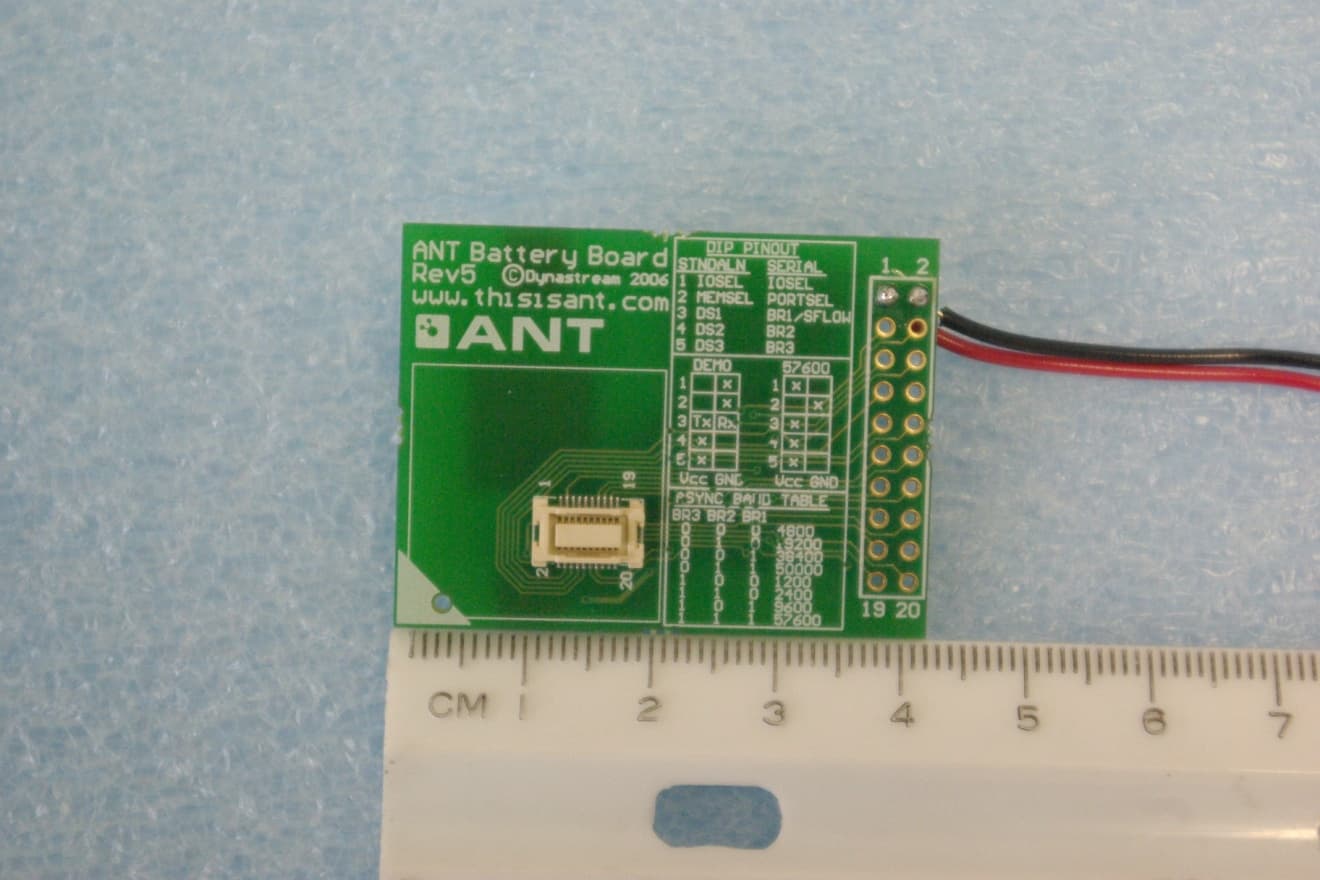
O6R1823
Sep 20, 2011LOW POWER TRANSMITTER (2400-2483.5 MHz)
Equipment Class
DXX - Part 15 Low Power Communication Device Transmitter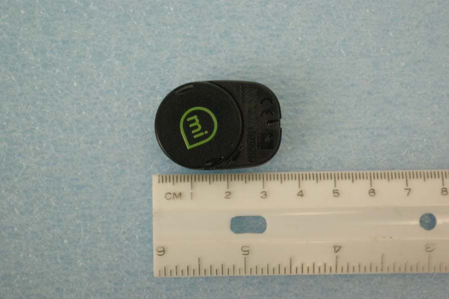
O6R01715
Jun 26, 2011LOW POWER TRANSMITTER (2400-2483.5 MHz)
Equipment Class
DXX - Part 15 Low Power Communication Device Transmitter