O6RM7NVSUUNTO FOOT POD
Garmin Canada Inc.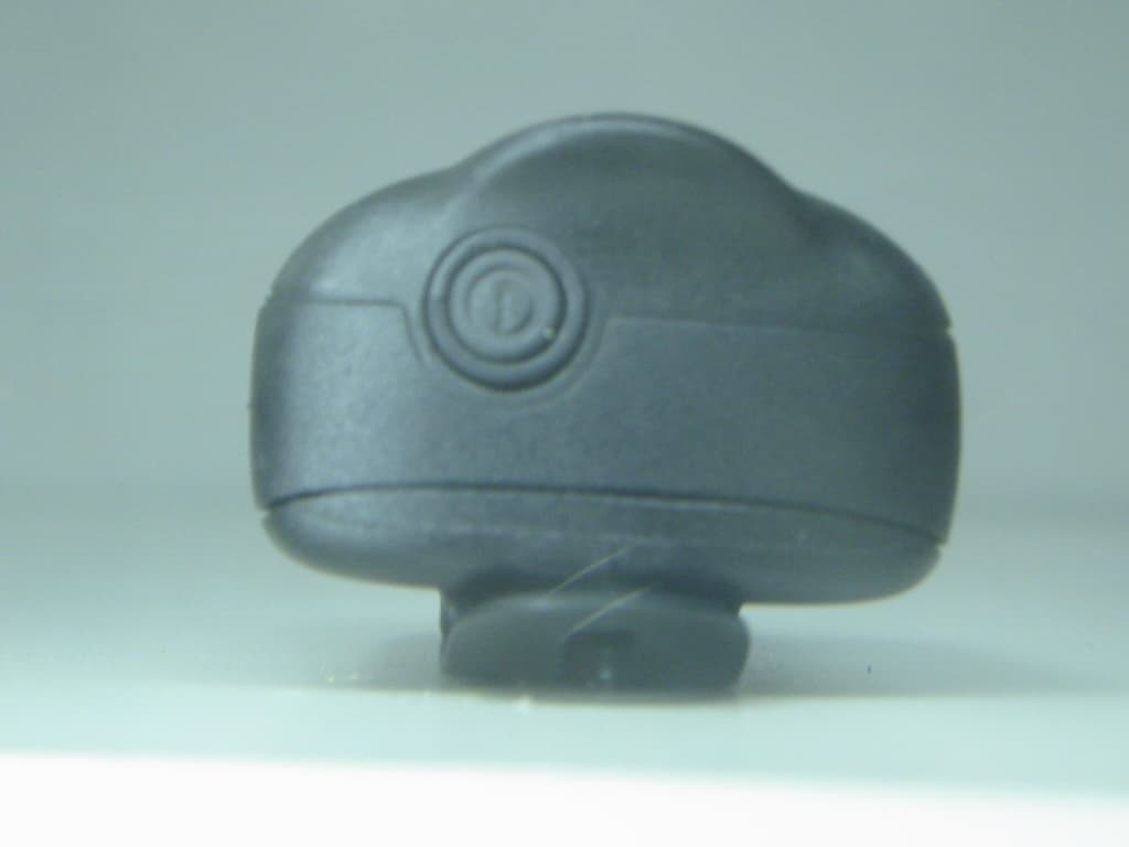
Click to zoom
Application Details
- Equipment Class
- DXX - Part 15 Low Power Communication Device Transmitter
- Date of Grant
- Jul 28, 2004
- Application Purpose
- Original Equipment
- Date of Application
- Jul 28, 2004
- Equipment Note
- SUUNTO FOOT POD
- Frequency Range
- 2465.00000000 - 2465.00000000
- Company
- Garmin Canada Inc.
- Country
- Canada
Documents & Files
Document Text
Text extracted from the exhibit documents filed with the FCC. Open a document above to read the original.
Users Manual
Max7NV Model Name Attn.: Arcelia Maldonado EMC Compliance Management Group 670 National Avenue, Mountain View, CA 94043 Date: July 23, 2004 To Whom It May Concern: Concerning the product model name. The Max7NV will be labeled and sold as the “Suunto Foot Pod™”. Please refer to the product labeling for additional information. Yours Sincerely, Victor Beda EET 1 CUSTOMER SERVICE CONTACTS Suunto OyPhone +358 9 875870 Fax+358 9 87587301 Suunto USAPhone 1 (800) 543-9124 CanadaPhone 1 (800) 776-7770 European Call Center Phone +358 2 284 11 60 PC-related questions [email protected] Suunto Website www.suunto.com 2 TABLE ON CONTENTS 1. GENERAL INFORMATION ...................................................................................6 1.1. CHECKLIST ................................................................................................. 7 1.2. GETTING STARTED ................................................................................... 7 1.3. SUUNTO T6 FEATURES ............................................................................ 8 1.4. CARE AND MAINTENANCE ....................................................................... 9 1.5. WATER RESISTANCE ................................................................................ 9 1.6. REPLACING THE BATTERY ....................................................................10 1.7. REPLACING THE BATTERY OF THE TRANSMITTER BELT ..................11 1.8. HEART RATE TRANSMITTER BELT ........................................................13 1.8.1. Activating the heart rate transmitter belt ..........................................13 1.8.2. Warnings .........................................................................................14 1.9. WIRELESS SPEED AND DISTANCE SENSORS .....................................14 1.9.1. Activating the wireless speed and distance sensor .........................14 2. HOW TO USE YOUR SUUNTO T6 ....................................................................15 2.1. DISPLAY AND BUTTONS .........................................................................15 2.1.1. Mode indicator .................................................................................16 2.1.2. Battery level indicator ......................................................................16 2.1.3. Alarm symbols .................................................................................16 2.1.4. Training symbols .............................................................................16 2.1.5. Key Lock ..........................................................................................17 2.2. MENUS ......................................................................................................18 2.2.1. Basic menu structure .......................................................................19 2.2.2. Press and long press .......................................................................19 3 2.2.3. Navigating in the menus ................................................................. 19 3. MODES ............................................................................................................... 21 3.1. GENERAL INFORMATION ....................................................................... 21 3.2. TIME MODE .............................................................................................. 21 3.2.1. Main display .................................................................................... 21 3.2.2. Alarm .............................................................................................. 22 3.2.3. Time ................................................................................................ 23 3.2.4. Date ................................................................................................ 24 3.2.5. General ........................................................................................... 25 3.2.6. Units ................................................................................................ 27 3.3. ALTI/BARO MODE .................................................................................... 33 3.3.1. Use (Alti/Baro) ................................................................................ 33 3.3.2. Alti use ............................................................................................ 34 3.3.3. Baro use ......................................................................................... 35 3.3.4. Reference altitude and barometric pressure ................................... 36 3.3.5. Memory ........................................................................................... 38 3.4. TRAINING ................................................................................................. 39 3.4.1. Stopwatch ....................................................................................... 40 3.4.2. Connect .......................................................................................... 40 3.4.3. Logbook .......................................................................................... 41 3.4.4. HR limits ......................................................................................... 43 3.4.5. Timers ............................................................................................. 44 3.4.6. Refer ............................................................................................... 47 3.4.7. History ............................................................................................. 47 3.4.8. Pair ................................................................................................. 48 4 3.4.9. Use (Alti/Baro) .................................................................................49 3.5. SPD/DST MODE ........................................................................................50 3.5.1. Main display .................................................................…
Text truncated - open the document above for the full version.
Cover Letter(s)
228 river ave, cochrane, alberta, canada T4C2C1 p 403.932.9292 f 403.932.6521 www.dynastream.com July 19, 2004 To: Federal Communications Commission 7435 Oakland Mills Road Columbia, MD 21046-1609 EMC Compliance Management Group 670 National Avenue Mountain View, CA 94043 Re: Confidentiality Request Gentlemen: This letter is to comply with 47 CFR 0.457(d)(2) pertaining to confidential material. Dynastream Innovations Inc requests that the following documents regarding this submission for FCC ID: 06RM7NV be kept confidential: 1. Schematics 2. Block Diagram 3. Operational / Technical Descriptions The material above contains technical data, which would customarily be guarded from competitors. Sincerely, Victor Beda Hardware Designer Dynastream Innovations Inc.
External Photos
Model Name: Suunto Foot Pod tm Tested Model Name: Max7NV EUT Front Side View Model Name: Suunto Foot Pod tm Tested Model Name: Max7NV EUT Back Side View Model Name: Suunto Foot Pod tm Tested Model Name: Max7NV Battery Side View
ID Label/Location Info
Model Name: Suunto Foot Pod tm Tested Model Name: Max7NV Label Location
Internal Photos
Model Name: Suunto Foot Pod tm Tested Model Name: Max7NV Model Name: Suunto Foot Pod tm Tested Model Name: Max7NV Model Name: Suunto Foot Pod tm Tested Model Name: Max7NV Model Name: Suunto Foot Pod tm Tested Model Name: Max7NV Model Name: Suunto Foot Pod tm Tested Model Name: Max7NV
Test Report
670 National Avenue, Mountain View, CA 94043 Tel. (650) 988-0900 Fax (650) 988-6647 www.emclab2000.com FCC 15.249 Test Report Final Model Name: Suunto Foot Pod tm Tested Model Name: Max7NV FCC ID: o6rm7nv IC: 3797A-M7NV Prepared for Dynastream Innovations, Inc. According to FCC Section 15.249 Test Report #: DYN-0406-4151-FCC Job Number #: DYN-0407-1001-TCB Prepared by: Arcelia Maldonado QC Manager: Tony Wang Test Report Released by: July 23, 2004 ⎯⎯⎯⎯⎯⎯⎯⎯⎯ ⎯⎯⎯⎯⎯⎯ Tony Wang Date NVLAP Lab code: 200068-0 ISO/IEC 17025:1999, ISO 9002:1994 List of Attached Files Exhibit Type File Description File Name Test Report Test Report report.pdf Operation Description Technical Description description.pdf Test Report Fundamental Field Strength Plot fds.pdf Test Report Band Edge Plots be.pdf Test Report Out of Band Emissions Plots obe.pdf Test Report 6dB Bandwidth Plot 6dB.pdf Test Report Duty Cycle Measurement dcm.pdf External Photos External Photos external-photos.pdf Internal Photos Internal Photos internal-photos.pdf Set-up Photos Test Set-up Photos setup-photos.pdf Block Diagram Block Diagram block.pdf Schematics Circuit Diagram circuit.pdf ID Label/Location Label Artwork and Location label.pdf User Manual User Manual manual.pdf Max7NV Model Name Attn.: Arcelia Maldonado EMC Compliance Management Group 670 National Avenue, Mountain View, CA 94043 Date: July 23, 2004 To Whom It May Concern: Concerning the product model name. The Max7NV will be labeled and sold as the “Suunto Foot Pod™”. Please refer to the product labeling for additional information. Yours Sincerely, Victor Beda EET Test Location EMC Compliance Management Group is located at 670 National Ave., Mountain View, CA 94043, USA. Accreditation Bodies EMC Compliance Management Group is a fully accredited Test Laboratory for ITE, ISM and Telecommunications Products. In compliance with the site registration requirements of Section 2.948 of the FCC Rules to perform EMI measurements for the general public. Accredited by the National Voluntary Laboratory Accreditation Program for the specific scope of accreditation under Lab Code # 200068-0. Table of Contents GOVERNMENT DISCLAIMER NOTICE __________________________ 1 REPRODUCTION CLAUSE _____________________________________ 1 ADMINISTRATIVE DATA ______________________________________ 2 EUT DESCRIPTION ___________________________________________ 2 TEST SUMMARY ______________________________________________ 3 TEST MODE JUSTIFICATION __________________________________ 4 EQUIPMENT MODIFICATION __________________________________ 4 TEST SYSTEM DETAILS _______________________________________ 5 TEST METHODOLOGY ________________________________________ 6 1. FCC 15.249 (A) FUNDAMENTAL FREQUENCY MEASUREMENT7 2. FCC PART 15.249 (B) AND (D) HARMONIC FREQUENCY MEASUREMENTS _____________________________________________ 8 3. FCC 15.249 (D) BAND EDGE AND OUT OF BAND MEASUREMENTS ____________________________________________ 11 4. FCC 15.249 (D) OCCUPIED 6 DB BANDWIDTH MEASUREMENTS ____________________________________________ 13 5. FCC 15.35 (B) AND (C) DUTY CYCLE CALCULATION _______ 14 6. FCC 15.209 RADIATED EMISSIONS LIMIT _________________ 15 7. FCC 15.207 (A) CONDUCTED EMISSION MEASUREMENT17-17 EMC Test Report #: DYN-0406-4151-FCC Prepared for Dynastream Innovations, Inc. Prepared by EMC Compliance Management Group Page 1 of 17 Government Disclaimer Notice When government drawing, specification, or other data are used for any purpose other than in connection with a definitely related government procurement operation, the United States Government thereby incurs no responsibility nor any obligation whatsoever; and the fact that the Government may have formulated, furnished, or in any way supplied the said drawing, specifications, or other data, is not to be regarded by implication or otherwise in any manner licensing the holder or any other person or corporation, or conveying any rights or permission to manufacture, use, or sell patented invention that may in any way be related thereto. This report must not be used to claim product endorsement by NVLAP or any agency of the U.S. Government. Reproduction Clause Any reproduction of this document must be done in full. No single part of this document may be reproduced without permission from EMC Compliance Management Group, 670 National Ave., Mountain View, CA 94043. EMC Test Report #: DYN-0406-4150-FCC Prepared for Dynastream Innovations, Inc. Prepared by EMC Compliance Management Group Page 2 of 17 ADMINISTRATIVE DATA Test Sample : Speed and Distance Monitoring System Model Name : Suunto Foot Pod tm Tested Model Name : Max7NV Serial Number : Engineering Sample Date Tested : June 10 th - 14 th , 2004 Manufacturer : Dynastream Innovations, Inc. 228 River Avenue, Cochrane, Alberta, Canada Telephone : (403) 932-9292 Fax : (403) 932-6521 EUT Description Dynastream Innovations, Inc., tested model name Max7NV (referred to as the EUT in this report) is a Speed and Distance Monitoring System. EMC Test Report #: DYN-0406-4150-FCC Prepared for Dynastream Innovations, Inc. Prepared by EMC Compliance Management Group Page 3 of 17 Test Summary The Electromagnetic Compatibility requirements on tested model name Max7NV for this test are stated below. All results listed in this report relate exclusively to this above-mentioned model as the Equipment Under Test. This report confers no approval or endorsement upon any other component, host or subsystem used in the test set-up. The Max7NV has been found to conform to the following parts of the 47 CFR FCC as detailed below: Part 15 Requirement Result Pass/Fail Comments 15.15(b) General technical requirements Pass The product contains no user accessible controls that increase transmission power above allowable levels. 15.19 Labeling requirement Pass The label is shown in the label exhibit. 15.21 Information to user Pass Information to the user is shown in the instruction manual exhibit. 15.27 Special accessories Pass No special accessori…
Text truncated - open the document above for the full version.
Test Setup Photos
EUT Setup Photos for Tested Model Name: Max7NV Harmonic Frequency Measurements Test Set-Up EUT Setup Photos for Tested Model Name: Max7NV Close-Up View EUT Setup Photos for Tested Model Name: Max7NV Radiated Emissions Test Set-up Close-Up View
Contact Information
Applicant
Jim Rooney(President)
Test Firm
EMC Compliance Management GroupPaul Chen
Technical Specifications
| # | Rule Parts | Frequency Range | Power Output |
|---|---|---|---|
| 1 | 15C | 2.46 GHz - 2.46 GHz | - |
Other Applications from Garmin Canada Inc.
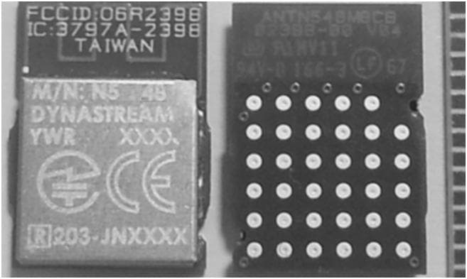
O6R2398
Mar 04, 2014N5
Equipment Class
DXX - Part 15 Low Power Communication Device Transmitter
O6R02162
Jun 19, 2013LOW POWER TRANSMITTER (2400-2483.5)
Equipment Class
DXX - Part 15 Low Power Communication Device Transmitter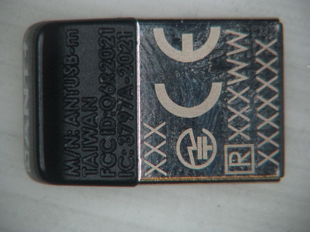
O6R2021
Jan 08, 2013LOW POWER TRANSMITTER (2400-2483.5 MHz)
Equipment Class
DXX - Part 15 Low Power Communication Device Transmitter
O6R1823
Sep 20, 2011LOW POWER TRANSMITTER (2400-2483.5 MHz)
Equipment Class
DXX - Part 15 Low Power Communication Device Transmitter
O6R01715
Jun 26, 2011LOW POWER TRANSMITTER (2400-2483.5 MHz)
Equipment Class
DXX - Part 15 Low Power Communication Device Transmitter