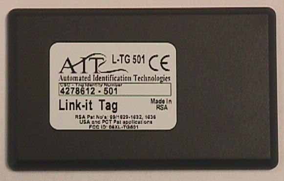
O6XL-TG501Link-it Tag, L-TG501
Wavetrend Technologies Limited
Click to zoom
Application Details
- Equipment Class
- DSC - Part 15 Security/Remote Control Transmitter
- Date of Grant
- Feb 01, 2001
- Application Purpose
- Original Equipment
- Date of Application
- Feb 01, 2001
- Equipment Note
- Link-it Tag, L-TG501
- Frequency Range
- 433.92000000 - 433.92000000
- Country
- United Kingdom
Documents & Files
Document Text
Text extracted from the exhibit documents filed with the FCC. Open a document above to read the original.
Users Manual
Link-it™ Product Information Sheet Active Tags L-TG501 (Slimline Tag) Description: The Link-it™ L-TG501 Active Tag is powered by an internal battery. The Tag will, for the duration of its life, transmit a Radio Frequency (RF) signal at a pre-set time-interval. The Tag life is estimated to be at least 5 years at a transmission t ime interval of approximately 15 seconds. The Tag is simply replaced when the battery has expired. Battery status can be inferred by interrogating the internal Tag Age Counter Value. Tag data that is transmitted includes Site / Vendor ID, Tag ID, Tag Age Counter Value, Movement Alarm and Tamper Alarm status. For protection against adverse environmental conditions, Link-it™ Tags are encapsulated in a moulded plastic case, which is ultrasonically sealed during the manufacturing process. In addition provides a constant RF power output which reduces makes system calibration easier as well as faster. The L-TG501 Tag is generally used for personnel tagging, although it may be used in other applications, ie. the external tagging of Laptop Computers. The mounting and affixing depends on the type of application. The standard method is by VHB type double sided adhesive tape. Several unique features of the Tag can be configured. For example: access control and weigand interfacing Link-it TM is a re gis tered trade mark o f AIT. Spec ificatio ns a nd prod uc t a va ilab ility s ub ject to c ha nge witho ut notice. Ta g a nd reader communication distances assume optimal orientation between tag and reader. Read distances may vary as a result of the prese nce o f meta l a nd e nviro nme nta l co nd itio ns. Re fe r to other p ub licatio ns fro m AIT re ga rd ing app lica tio n p ractises for RF tagging. RSA Patent numbers: 99/1629, 1630, 1631, 1632, 1636, 1673 USA and PCT patents pending For more information on this and other products and services available contact: Auto mate d Ide ntifica tio n Te chnologie s (Pty ) Ltd 2B, The C loisters O ffice Park, cnr Rivonia Boulevard & 9 th Avenue, Rivonia P.O. Box 490, Parklands, 2121, South Africa. Tel +27 (0)11 807 0911, Fax +27 (0)11 807 0915 Email: [email protected] Internet: ait-linkit.com Auto mate d Ide ntifica tio n Te chnologie s Ltd. Unit 6, Amber Business Village Amber C lose, Tamworth Staffordshire, B77 4RP United Kingdom Tel +44 1827 311 331 Fax +44 1827 311 661 Revision Date: 02/05/01 Features: • Configurable settings, including Site / Vendor ID, Tag ID, Transmission Repetition Interval and Alarm functions. • Low power consumption. Tag life is estimated to be at least 5 years when transmitting at a 15-second interval. • Proprietary Encryption Method Applications: Link-it™ Tags can be mounted on a wide variety of items. Where permanent fixing is required VHB double sided tape is used. Where permanent mounting is not required, the tags may simply be carried by a person (typically if used as a person identifier) with a clip attachment, or inserted in a carry pouch and worn around the neck Specification: Environmental Operational temperature-10º C to +60º C Storage temperature-20º C to +70º C Humidity5% to 90% (non condensing) Physical Size86mm x 54mm x 5mm (Slimline Enclosure) Weight<25gms ColourDark Grey(Clariant 04-600 2%) Type of materialPVC (ultrasonically sealed) IP 65 RF Specifications Frequency433.92Mhz RF Output Power< 300μW Typical Transmission Range8 Meters (24 feet) Link-it™ Product Information Sheet Certification : This device complies with Part 15 of the FCC Rules. Operation is subject to the following two conditions: (1) this device may not cause harmful interference, and (2) this device must accept any interference received, including interference that may cause undesired operation. This device has been tested and found to comply with the limits for a Class B digital device, pursuant to Part 15 of the FCC Rules. These limits are designed to provide reasonable protection against harmful interference in a residential installation. This device generates, uses, and can radiate radio frequency energy and, if installed and used in accordance with the instruction, may cause harmful interference to radio communications. However, there is no guarantee that interference will not occur in a particular installation. If this device does cause harmful interference to radio or television reception, the user is encouraged to try to correct the interference by one or more of the following measures: • Reorient or relocate the receiving antenna. • Increase the separation between the computer and receiver. • Connect the computer into an outlet on a circuit different from that to which the receiver is connected. • Consult the dealer or an experienced radio/TV technician for help. Caution: Any changes or modifications not expressly approved by the grantee of this device could void the user’s authority to operate the equipment.
Cover Letter(s)
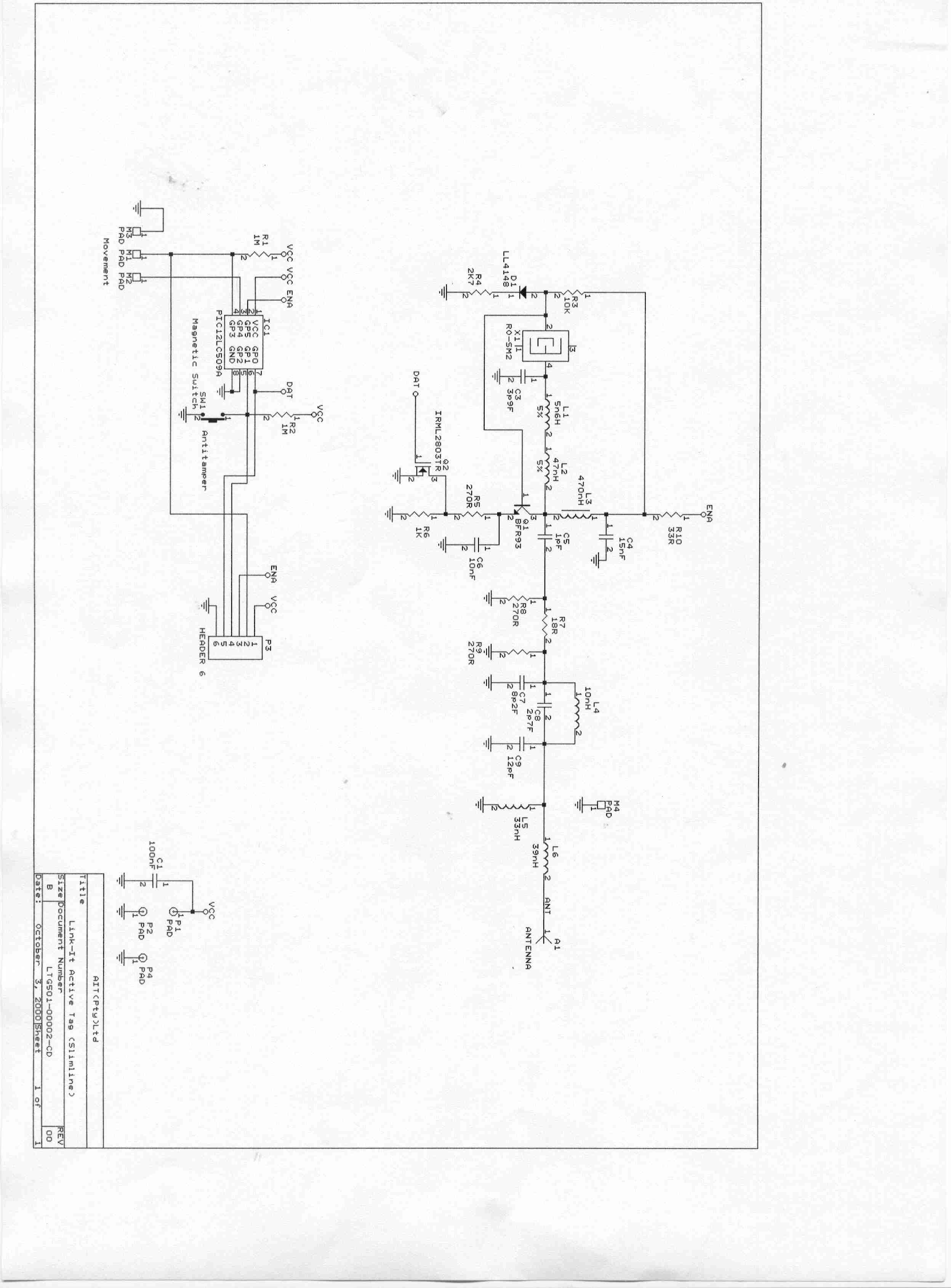
Federal Communications Commission 7435 Oakland Mills Road Columbia, MD 21046 Gentlemen: This letter is to comply with Section 0.457(d)(2) pertaining to confidential material. Automated Identification Technologies would like the following document regarding this submission for FCC ID: O6XL-TG501 to be kept confidential. 1. Pages 10 of 10 of document Technical Construction File for the Link-it Tag L- TG501, document number EAB-00001-01-UC. 2. Block diagram The above material contains trade secrets or technical data, which would customarily be guarded from competitors. We do not want these documents to be accessible to the general public. Sincerely, Joyce Walker Report Department Manager CKC Laboratories, Inc. Agent for Automated Identification Technologies
Cover Letter(s)
Responses to Non-Conformities FCC ID: O6XLTG500 (Ref # E01-000009-1) Item 1: Please upload the operational description and block diagrams to their appropriate exhibit. The confidentiality letter will have to updated. Files uploaded separately January 30, 2001. Item 2: The device appears to be large enough to fit the statements required in 15.19. Please explain/provide. Customer comments: The labels we have will have to be redesigned and as you know we are in the process of making new moulds and labels. Our technical director in the mean time suggested that we add the following attached label - even if we need to stick it to the other side of the tag. A new label has been uploaded. This label will be placed on the back of the unit. Item 3: Please provide a copy of the installation and operating instructions that will be furnished to the user. The Product Information Sheet is the only manual that will be provided with the transmitter tag.
Cover Letter(s)
1) Operational description (called TCF) is uploaded to the correct exhibit. The block diagram was revised and put into its appropriate exhibit. 2) Customer comments: The labels we have will have to be redesigned and as you know we are in the process of making new moulds and labels. Our technical director in the mean time suggested that we add the following attached label - even if we need to stick it to the other side of the tag. A new label has been uploaded. This label will be placed on the back of the unit. 3) The Product Information Sheet is the only manual that will be provided with the transmitter tag.
ID Label/Location Info
FCC Standard Tested This device complies with Part 15 of the FCC rules. Operation is subject to the following two conditions : (1) this device m ay not cause harmful interference, and (2) this device must accept any interference received, including interference that may cause undesired operation.
Test Report
Page 1 of 51 Report No: FC00-113 VERIFICATION TEST REPORT FOR THE LINK-IT TAG (TRANSMITTER) AND READER (RECEIVER), L-TG501 AND L-RX100 FCC PART 15 SUBPART B SECTIONS 15.107, 15.109 & 15.111 AND FCC PART 15 SUBPART C SECTION 15.231 COMPLIANCE DATE OF ISSUE: DECEMBER 13, 2000 PREPARED FOR: Automated Identification Technologies (Pty) P.O. Box 490, Block 2B Upper Level Cnr Rivonia Blvd. & 9 th Avenue/Rivonia Parklands, South Africa 2121 P.O. No: P2001000621 W.O. No: 75638 PREPARED BY: Joyce Walker CKC Laboratories, Inc. 5473A Clouds Rest Mariposa, CA 95338 Date of test: November 27 through December 5, 2000 Report No: FC00-113 DOCUMENTATION CONTROL: _____________________________ Tracy Phillips Documentation Control Supervisor CKC Laboratories, Inc. APPROVED BY: _____________________________ Dennis Ward Director of Laboratories CKC Laboratories, Inc. This report contains a total of 51 pages and may be reproduced in full only. Partial reproduction may only be done with the written consent of CKC Laboratories, Inc. Page 2 of 51 Report No: FC00-113 TABLE OF CONTENTS Administrative Information ............................................................................................. 4 Summary Of Results........................................................................................................ 5 Equipment Under Test (EUT) Description...................................................................... 5 Measurement Uncertainty................................................................................................ 5 EUT Operating Frequency............................................................................................... 5 Peripheral Devices ........................................................................................................... 6 Report Of Measurements................................................................................................. 7 Table 1: Fundamental Radiated Emission Levels - Transmitter ........................ 7 Table 2: Highest Radiated Emission Levels - 30-1000 MHz - Transmitter ....... 8 Table 3: Six Highest Radiated Emission Levels - 1-4.33 GHz - Transmitter .... 9 Table 4: Six Highest Antenna Conducted Emission Levels - Receiver ............. 10 Table 5: Six Highest Radiated Emission Levels - 30-1000MHZ - Receiver ..... 11 Table 6: Radiated Emission Levels - 1-4.33 GHz - Receiver ............................ 12 Table 7: Six Highest Conducted Emission Levels - Receiver............................ 13 Table A : List Of Test Equipment ................................................................................... 14 EUT Setup .......................................................................................................................15 Test Instrumentation And Analyzer Settings................................................................... 16 Table B : Analyzer Bandwidth Settings Per Frequency Range........................... 16 Spectrum Analyzer Detector Functions............................................................... 17 Peak ......................................................................................................... 17 Quasi-Peak............................................................................................... 17 Average.................................................................................................... 17 Test Methods ...................................................................................................................18 Radiated Emissions Testing................................................................................. 18 Conducted Emissions Testing ............................................................................. 19 Occupied Bandwidth ........................................................................................... 19 Antenna Conducted Measurements ..................................................................... 19 Sample Calculations ........................................................................................................ 20 Appendix A : Information About The Equipment Under Test........................................ 21 Receiver I/O Ports ............................................................................................... 22 Receiver Crystal Oscillators ................................................................................ 22 Printed Circuit Boards ......................................................................................... 22 Required EUT Changes To Comply.................................................................... 22 Photograph Showing Radiated Emissions - Transmitter ..................................... 24 Photograph Showing Radiated Emissions - Transmitter ..................................... 25 Photograph Showing Antenna Conducted - Receiver ......................................... 26 Photograph Showing Radiated Emissions ........................................................... 27 Photograph Showing Radiated Emissions - Receiver ......................................... 28 Photograph Showing Conducted Emissions - Receiver ...................................... 29 Photograph Showing Conducted Emissions - Receiver ...................................... 30 Page 3 of 51 Report No: FC00-113 Appendix B : Measurement Data Sheets ......................................................................... 31 Occupied Bandwidth Plot.................................................................................... 32 Occupied Bandwidth Plot.................................................................................... 33 Pulse Duration Plot.............................................................................................. 34 Pulse Duration Plot.............................................................................................. 35 Pulse Repetition Plot ...................................................................…
Text truncated - open the document above for the full version.
Test Setup Photos
Page 24 of 51 Report No: FC00-113 PHOTOGRAPH SHOWING RADIATED EMISSIONS - TRANSMITTER Radiated Emissions - Transmitter Flat Page 25 of 51 Report No: FC00-113 PHOTOGRAPH SHOWING RADIATED EMISSIONS - TRANSMITTER Radiated Emissions - Transmitter on Edge Page 26 of 51 Report No: FC00-113 PHOTOGRAPH SHOWING ANTENNA CONDUCTED - RECEIVER Antenna Conducted Emissions - Front View of Receiver Page 27 of 51 Report No: FC00-113 PHOTOGRAPH SHOWING RADIATED EMISSIONS Radiated Emissions - Front View of Receiver Page 28 of 51 Report No: FC00-113 PHOTOGRAPH SHOWING RADIATED EMISSIONS - RECEIVER Radiated Emissions - Back View of Receiver Page 29 of 51 Report No: FC00-113 PHOTOGRAPH SHOWING CONDUCTED EMISSIONS - RECEIVER Conducted Emissions - Front View of Receiver Page 30 of 51 Report No: FC00-113 PHOTOGRAPH SHOWING CONDUCTED EMISSIONS - RECEIVER Conducted Emissions - Side View of Receiver
Contact Information
Applicant
Will Damerell(Technical Director)
Technical Contact
CKC Laboratories, Inc.Tracy Phillips
[email protected]800 500 4362
5473A Clouds Rest · Mariposa, California · United States
Non-Technical Contact
CKC Laboratories, Inc.Joyce Walker
[email protected]800 500 4362
Test Firm
CKC Laboratories, Inc.Steve Behm
Technical Specifications
| # | Rule Parts | Frequency Range | Power Output |
|---|---|---|---|
| 1 | 15.231(e) | 433.92 MHz - 433.92 MHz | - |
Other Applications from Wavetrend Technologies Limited

O6XTGF-A
Aug 10, 2012Active Duo RFID Tag TGF-A
Equipment Class
DXX - Part 15 Low Power Communication Device Transmitter
O6XTGM-A
Aug 10, 2012Active Duo RFID Tag TGM-A
Equipment Class
DXX - Part 15 Low Power Communication Device Transmitter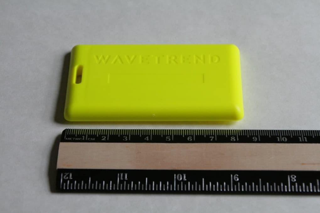
O6XTGP-A
May 29, 2012Active Duo RFID Tag TGP-A
Equipment Class
DXX - Part 15 Low Power Communication Device Transmitter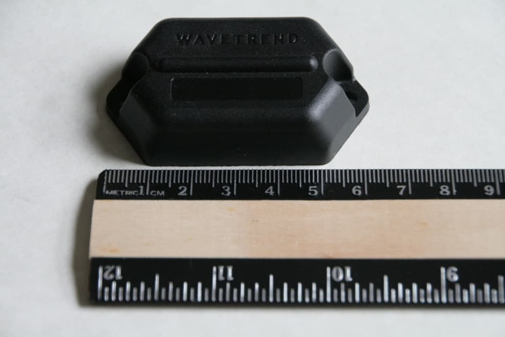
O6XTGA-A
May 29, 2012Active Duo RFID Tag TGA-A
Equipment Class
DXX - Part 15 Low Power Communication Device Transmitter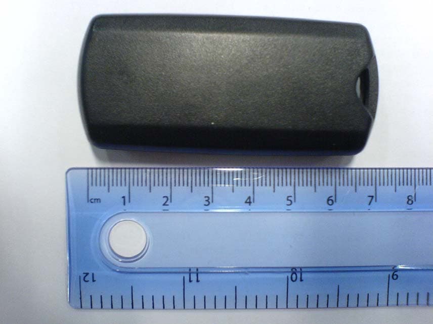
O6XTG801
Jul 25, 2007Asset Tag - Mini
Equipment Class
DSR - Part 15 Remote Control/Security Device Transceiver