O7VMA191823Wireless Speaker
MONITOR AUDIO LTD.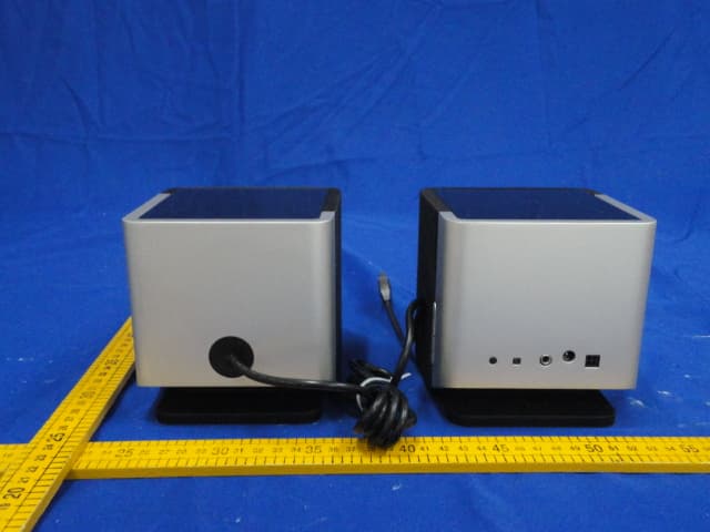
Click to zoom
Application Details
- Equipment Class
- DSS - Part 15 Spread Spectrum Transmitter
- Date of Grant
- Jul 02, 2012
- Application Purpose
- Original Equipment
- Date of Application
- Jul 02, 2012
- Equipment Note
- Wireless Speaker
- Frequency Range
- 2403.58500000 - 2477.31300000
- Company
- MONITOR AUDIO LTD.
- Country
- United Kingdom
Documents & Files
Document Text
Text extracted from the exhibit documents filed with the FCC. Open a document above to read the original.
Users Manual
Quick Start Guide Wireless Speaker Title: i-Deck Remote Control ArtworkDate: 15th February 2010 Notes:1. ICONS TO BE SILKSCREENED PANTONE REFERENCE COOL GREY 1M2. LOGO & TEXT TO BE PRINTED AS BLACK UV SPOT3. IMAGE FOR REFERENCE PURPOSES ONLY.4. VERSION 2 I M PORTANT S A FETY I N S T RUCT I O N S A I R S TREA M GB - SAFETY INSTRUCTIONS FR - CONSIGNES DE SÉCURITÉ IT - ISTRUZIONI PER LA SICUREZZA DE - SICHERHEITSANWEISUNGEN ES - INSTRUCCIONES DE SEGURIDAD PT - INSTRUÇÕES DE SEGURANÇA NL - VEILIGHEIDSINSTRUCTIES CH - 安全說明 RU - инс тр укции по технике безопа снос ти RU - у словия г ар антии I M PORTANT S A FETY I N S T RUCT I O N S A I R S TREA M GB - SAFETY INSTRUCTIONS FR - CONSIGNES DE SÉCURITÉ IT - ISTRUZIONI PER LA SICUREZZA DE - SICHERHEITSANWEISUNGEN ES - INSTRUCCIONES DE SEGURIDAD PT - INSTRUÇÕES DE SEGURANÇA NL - VEILIGHEIDSINSTRUCTIES CH - 安全說明 RU - инс тр укции по технике безопа снос ти RU - у словия г ар антии Q uick Start Guide Wireless Speaker Title: i-Deck Remote Control Artwork Date: 15th February 2010 Notes: 1. ICONS TO BE SILKSCREENED PANTONE REFERENCE COOL GREY 1M 2. LOGO & TEXT TO BE PRINTED AS BLACK UV SPOT 3. IMAGE FOR REFERENCE PURPOSES ONLY. 4. VERSION 2 www.monitoraudio.com Title: i-Deck Remote Control Artwork Date: 15th February 2010 Notes: 1. ICONS TO BE SILKSCREENED PANTONE REFERENCE COOL GREY 1M 2. LOGO & TEXT TO BE PRINTED AS BLACK UV SPOT 3. IMAGE FOR REFERENCE PURPOSES ONLY. 4. VERSION 2 Title: i-Deck Remote Control Artwork Date: 15th February 2010 Notes: 1. ICONS TO BE SILKSCREENED PANTONE REFERENCE COOL GREY 1M 2. LOGO & TEXT TO BE PRINTED AS BLACK UV SPOT 3. IMAGE FOR REFERENCE PURPOSES ONLY. 4. VERSION 2 + + - - Monitor Audio Ltd. 24 Brook Road Rayleigh, Essex SS6 7XJ England Tel: +44 (0)1268 740580 Fax: +44 (0)1268 740589 Email: [email protected] Designed and Engineered in the United Kingdom © Monitor Audio. Version 1 2012 The SKAA TM logo is a registered trademark of Eleven Engineering Inc. i Important safety InstructIons aIrstream GB - Safety InStructIonS fr - conSIGneS de SécurIté It - IStruzIonI per la SIcurezza de - SIcherheItSanweISunGen eS - InStruccIoneS de SeGurIdad pt - InStruçõeS de SeGurança nl - VeIlIGheIdSInStructIeS CH - 安全說明 RU - инструкции по технике безопасности RU - условия гарантии WARNING • TO PREVENT FIRE OR SHOCK HAZARD, DO NOT USE THIS PLUG WITH AN EXTENSION CORD, RECEPTACLE OR OTHER OUTLET UNLESS THE BLADES CAN BE FULLY INSERTED TO PREVENT BLADE EXPOSURE • TO PREVENT FIRE OR SHOCK HAZARD, DO NOT EXPOSE THIS APPLIANCE TO RAIN OR MOISTURE • TO PREVENT ELECTRIC SHOCK, MATCH WIDE BLADE PLUG TO WIDE SLOT AND FULLY INSERT. This lightning flash with an arrow head symbol, within an equilateral triangle, is intended to alert the user to the presence of un-insulated “dangerous voltage” within the product’s enclosure that may be of sufficient magnitude to constitute a risk of electric shock to the persons. Warning: To reduce the risk of electric shock, do not remove cover (or back), no user- serviceable parts inside. Refer servicing to qualified service personnel. This exclamation point within an equilateral triangle is intended to alert the user to presence of important maintenance (servicing) instructions in the literature accompanying the appliance. This is a “Class II”, “double insulated apparatus”. This apparatus must NOT have a safety connection to Earth. enGLIsH 1monitoraudio.co.uk Important safety InstructIons 1. Read these instructions. 2. Keep these instructions. 3. Heed all warnings. 4. Follow all instructions. 5. Do not use this apparatus with water. 6. Clean only with a dry cloth. Great care and attention has gone into the materials chosen to produce the product. A gentle wipe with a dry, clean cloth is all that is required to remove any dust. Treat it as you would a fine piece of furniture because that is how they have been designed. 7. Do not block any ventilation openings. Install in accordance with Monitor Audio’s instructions. 8. Do not install near any heat source, such as radiators, heat registers, stoves, or other apparatus (including amplifiers) that produce heat. 9. Do not defeat the purpose of the polarised or grounding type plug. A polarised plug has two blades with one wider than the other. A grounding type plug has two blades and a third grounding prong. The wider blade or the third prong are provided for your safety. If the provided plug does not fit your outlet, consult an electrician for replacement of the obsolete outlet. 10. Protect the power cord from being walked on or pinched particularly at plugs, convenience receptacles, and the point where they exit from the apparatus. 11. Only use attachments/ accessories specified by Monitor Audio. 12. Use only with the cart, stand, tripod, bracket, or table specified by the manufacturer or sold with the apparatus. When a cart is used, use caution when moving the cart/ apparatus combination to avoid injury from tip-over. 13. Unplug this apparatus during lightening storms, or when unused for long periods of time. 14. Refer all servicing to qualified service personnel. Servicing is required when the apparatus has been damaged in any way, such as power supply cord or plug is damaged, liquid has been spilled or objects have fallen onto the apparatus, the apparatus has been exposed to rain or moisture, does not operate normally or has been dropped. 15. This apparatus shall not be exposed to dripping or splashing water and that no object filled with liquids such as vases shall be placed on the apparatus. 16. The appliance coupler is used as the disconnect device, the disconnect device shall remain readily operable. 17. This exclamation point within an equilateral triangle is intended to alert the user to the presence of important maintenance (servicing) instructions in the literature accompanying the appliance. batterIes 1. WARNING: The battery (battery or batteries or battery pack) shall not be exposed to excessive heat such as sunshine, fire or the like 2. No naked fl…
Text truncated - open the document above for the full version.
External Photos
FCC ID: O7VMA191823 EST Technology Co.,Ltd Report No.ESTE-R1205004 Page 82 of 88 13. PHOTOS OF EUT External Photos FCC ID: O7VMA191823 EST Technology Co.,Ltd Report No.ESTE-R1205004 Page 83 of 88 External Photos
ID Label/Location Info
DC Input: 20V 3.25A Power: 65W Stand by: 0.5W Only use the power adaptor provided. Designed in the UK, Made in China. IC : 5928A-MA191823 FCC ID: O7VMA191823 This device complies with part 15 of the FCC Rules. Operation is subject to the following two conditions: (1) This device may not cause harmful interference, and (2) This device must accept any interference received, including interference that may cause undesired operation. www.monitoraudio.com Model: AirStream WS100
Internal Photos
FCC ID: O7VMA191823 EST Technology Co.,Ltd Report No.ESTE-R1205004 Page 84 of 88 Internal Photos FCC ID: O7VMA191823 EST Technology Co.,Ltd Report No.ESTE-R1205004 Page 85 of 88 Internal Photos FCC ID: O7VMA191823 EST Technology Co.,Ltd Report No.ESTE-R1205004 Page 86 of 88 Internal Photos Antenna FCC ID: O7VMA191823 EST Technology Co.,Ltd Report No.ESTE-R1205004 Page 87 of 88 Internal Photos FCC ID: O7VMA191823 EST Technology Co.,Ltd Report No.ESTE-R1205004 Page 88 of 88 Internal Photos
RF Exposure Info
FCC ID: O7VMA191823 EST Technology Co.,Ltd Report No. ESTE-R1205002 Page 1 of 3 FCC 47 CFR MPE REPORT MONITOR AUDIO LTD Wireless Speaker Model Number: AirStream WS100 FCC ID: O7VMA191823 Prepared for : MONITOR AUDIO LTD Unit 2, 24 Brook Road, Rayleigh, Essex England SS6 7XJ United Kingdom Prepared By : EST Technology Co., Ltd. Santun(guantai Road), Houjie Town, DongGuan City,GuangDong, China. Tel: 86-769-83081888-808 Report Number: ESTE-R1205002 Date of Test : May.3~18, 2012 Date of Report : May.19, 2012 FCC ID: O7VMA191823 EST Technology Co.,Ltd Report No. ESTE-R1205002 Page 2 of 3 Maximum Permissible Exposure 1、Applicable Standard Systems operating under the provisions of this section shall be operated in a manner that ensures that the public is not exposed to radio frequency energy level in excess limit for maximum permissible exposure. In accordance with 47 CFR FCC Part 2 Subpart J, section 2.1091 this device has been defined as a mobile device whereby a distance of 0.2m normally can be maintained between the user and the device. (a)、Limits for Occupational / Controlled Exposure Frequency Range (MHz) Electric Field Strength E) (V/m) Magnetic Field Strength (H) (A/m) Power Density (S) (mW/cm2) Averaging Times︱E︱ 2 , ︱H︱2 or S (minutes) 0.3-3.0 614 1.63 (100)* 6 3.0-30 1842/f 4.89/f (900/f)* 6 30-300 61.4 0.163 1.0 6 300-1500 F/300 6 1500-10000 5 6 (b)、Limits for General Population / Uncontrolled Exposure Frequency Range (MHz) Electric Field Strength E) (V/m) Magnetic Field Strength (H) (A/m) Power Density (S) (mW/cm2) Averaging Times︱E︱ 2 , ︱H︱2 or S (minutes) 0.3-1.34 614 1.63 (100)* 30 1.34-30 824/f 2.19/f (180/f)* 30 30-300 27.5 0.073 0.2 30 300-1500 F/1500 30 1500-10000 1.o 30 Note: f=frequency in MHz; *Plane-wave equivalent power density 2、MPE Calculation Method E (V/m) = (30*P*G) 0.5/d Power Density: Pd (W/m2) = E2/377 E = Electric Field (V/m) P = Peak RF output Power (W) G = EUT Antenna numeric gain (numeric) d = Separation distance between radiator and human body (m) The formula can be changed to Pd = (30*P*G) / (377*d2) From the peak EUT RF output power, the minimum mobile separation distance, d=0.2m, as well as the gain of the used antenna, the RF power density can be obtained FCC ID: O7VMA191823 EST Technology Co.,Ltd Report No. ESTE-R1205002 Page 3 of 3 3、Calculated Result and Limit 3.1. Power From Adapter 1 Antenna gain Channel Frequency (MHz) Peak output power (dBm) Peak output power (mW) (dBi) (Linear) Power Density (S) (mW/cm2) Limited of Power Density (S) (mW/cm2) Test Result 1 2403.585 16.36 43.252.21.66 0.0142 1 Compiles 24 2438.913 16.57 45.392.21.66 0.0150 1 Compiles 49 2477.313 16.21 41.782.21.66 0.0137 1 Compiles 3.2. Power From Adapter 2 Antenna gain Channel Frequency (MHz) Peak output power (dBm) Peak output power (mW) (dBi) (Linear) Power Density (S) (mW/cm2) Limited of Power Density (S) (mW/cm2) Test Result 1 2403.585 16.33 42.952.21.66 0.0141 1 Compiles 24 2438.913 16.48 44.462.21.66 0.0147 1 Compiles 49 2477.313 16.20 41.682.21.66 0.0137 1 Compiles
Test Report
FCC ID: O7VMA191823 EST Technology Co.,Ltd Report No.ESTE-R1205004 Page 1 of 92 FCC PART 15C TEST REPORT FOR CERTIFICATION On Behalf of MONITOR AUDIO LTD Wireless Speaker Model Number: AirStream WS100 FCC ID: O7VMA191823 Prepared for : MONITOR AUDIO LTD Unit 2, 24 Brook Road, Rayleigh, Essex England SS6 7XJ United Kingdom Prepared By : EST Technology Co., Ltd. Santun(guantai Road), Houjie Town, DongGuan City,GuangDong, China. Tel: 86-769-83081888-808 Report Number: ESTE-R1205004 Date of Test : May.3~18, 2012 Date of Report : May.19, 2012 FCC ID: O7VMA191823 EST Technology Co.,Ltd Report No.ESTE-R1205004 Page 2 of 92 TABLE OF CONTENTS Description Page TEST REPORT VERIFICATION.........................................................................................................................3 1. GENERAL INFORMATION.................................................................................................................5 1.1. Description of Device (EUT) ........................................................................................................... 5 2. SUMMARY OF TEST.........................................................................................................................6 2.1. Summary of test result...................................................................................................................... 6 2.2. Test Facilities ................................................................................................................................... 7 2.3. Assistant equipment used for test ..................................................................................................... 8 2.4. Block Diagram ................................................................................................................................. 8 2.5. Test mode ......................................................................................................................................... 8 2.6. Test Equipment................................................................................................................................. 9 3. MAXIMUM PEAK OUTPUT POWER.................................................................................................10 3.1. Limit ............................................................................................................................................... 10 3.2. Test Procedure ................................................................................................................................ 10 3.3. Test Result ...................................................................................................................................... 10 3.4. Test Data ........................................................................................................................................ 11 4. 20 DB BANDWIDTH.......................................................................................................................15 4.1. Limit ............................................................................................................................................... 15 4.2. Test Procedure ................................................................................................................................ 15 4.3. Test Result ...................................................................................................................................... 15 4.4. Test Data ........................................................................................................................................ 16 5. CARRIER FREQUENCY SEPARATION..............................................................................................20 5.1. Limit ............................................................................................................................................... 20 5.2. Test Procedure ................................................................................................................................ 20 5.3. Test Result ...................................................................................................................................... 20 5.4. Test Data ........................................................................................................................................ 21 6. NUMBER OF HOPPING CHANNEL..................................................................................................25 6.1. Limit ............................................................................................................................................... 25 6.2. Test Procedure ................................................................................................................................ 25 6.3. Test Result ...................................................................................................................................... 25 6.4. Test Data ........................................................................................................................................ 26 7. DWELL TIME.................................................................................................................................28 7.1. Limit ............................................................................................................................................... 28 7.2. Test Result ...................................................................................................................................... 28 7.3. Test Data ........................................................................................................................................ 29 8. RADIATED EMISSIONS....................................................................................................................31 8.1. Limit .....................................................................................................…
Text truncated - open the document above for the full version.
Test Setup Photos
FCC ID: O7VMA191823 EST Technology Co.,Ltd Report No.ESTE-R1205004 Page 80 of 88 12. TEST SETUP PHOTO Conducted Test FCC ID: O7VMA191823 EST Technology Co.,Ltd Report No.ESTE-R1205004 Page 81 of 88 Radiated Test (30-1000 MHz) Radiated Test (1000-25000 MHz)
Contact Information
Applicant
Thomas Fall(Quality Manager)
Test Firm
EST Technology Co.,LtdIceman Hu
[email protected]86-769-83081888
Technical Specifications
| # | Rule Parts | Frequency Range | Power Output |
|---|---|---|---|
| 1 | 15C | 2.40 GHz - 2.48 GHz | 45.39 mW |
Other Applications from MONITOR AUDIO LTD.

O7V-MA104210
Jan 21, 2026Caspian 4G Streaming Amplifier / Integrated Amplifier
Equipment Class
DSS - Part 15 Spread Spectrum TransmitterO7VMA120201
Jul 12, 2021Amplifier
Equipment Class
DTS - Digital Transmission System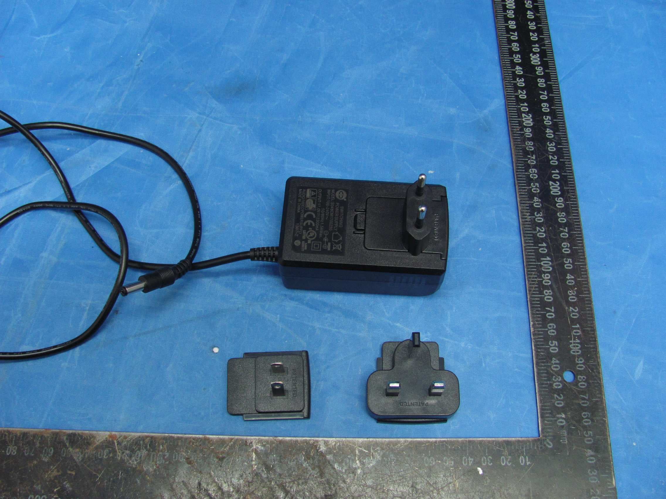
O7VMA191815
May 19, 2015airstream s150
Equipment Class
DSS - Part 15 Spread Spectrum Transmitter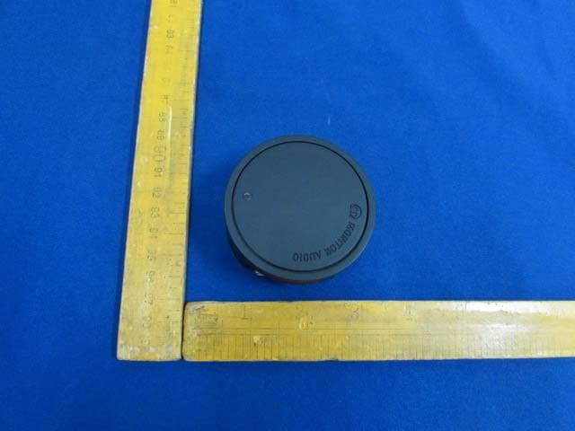
O7VMA232015
Jan 21, 2015Wireless Transmitter
Equipment Class
DXX - Part 15 Low Power Communication Device Transmitter
O7VMA191522
Aug 11, 2013ASB-2
Equipment Class
DTS - Digital Transmission System