O8712865MINIATURE POCSAG UHF TRANSMITTER
Sea Air and Land Communications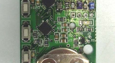
Click to zoom
Application Details
- Equipment Class
- TNB - Licensed Non-Broadcast Station Transmitter
- Date of Grant
- Jul 07, 2014
- Application Purpose
- Original Equipment
- Date of Application
- Jul 07, 2014
- Equipment Note
- MINIATURE POCSAG UHF TRANSMITTER
- Frequency Range
- 440.00000000 - 470.00000000
- Country
- New Zealand
Documents & Files
Document Text
Text extracted from the exhibit documents filed with the FCC. Open a document above to read the original.
Users Manual
12-86-5000 POCSAG Miniature Paging Transmitter PCB PRODUCT INFORMATION SEA AIR & LAND COMMUNICATION S LTD, CHRISTCHURCH, NEW ZEALAND SALCOM 12-86-5000 Miniature Paging Transmitter PCB ISSUE: 12865000UC 0714 Sea Air and Land Communications Ltd Page 1 12-86-5000 POCSAG Miniature Paging Transmitter PCB GENERAL The 12-86-5000 is a small, high specification, low cost Paging transmitter PCBmeasuring 60mm by 31mm and only 6mm deep with battery fitted. The 12-86-5000 has been tested and type approved as a bare PCB, allowing an easyroute to compliance for OEM’sThe 12-86 range of products are POCSAG direct to pager transmitters, allowing lowcost systems to be developed since intermediate receivers and transmitters are notrequired for short range applications.12-86 transmitters support up to 5 inputs, each of which can be programmed with upto a 35 character message. Programming can either with a serial programming cable that can be purchasedseparately or preprogrammed when supplied.A “Flash and Cancel” feature allows the 12-86-5000 to be programmed to flash the redLED for a period of time after each transmission. This allows the originatingtransmission source to be easily identified. Although the 12-86 is a low power transmitter, a direct line of sight transmission rangeof up to 200 metres can be expected. Transmit range within buildings is reduced, butstill considerable having proven to be effe ctive in some cases between floors and across buildings. OPERATION Pressing any button will result in the POCSAG transmission of a pre-programmedmessage assigned to that button. The red transmit LED will illuminate for the durationof the transmission.The red transmit LED can also be used as an indication of battery health, and shouldthe LED be dim or fail to light, the CR2032 button cell should be replaced. SALCOM 12-86-5000 Miniature Paging Transmitter PCB ISSUE: 12865000UC 0714 Sea Air and Land Communications Ltd Page 2 PROGRAMMING In order to program the12-86-5000, programming software should be downloadedfrom the Salcom website (www.salcom.co.nz). A Salcom 12-47 programming lead is required to program the 12-86 transmitters (thesame lead used to program the 11-85 transmitters). This may be purchasedseparately. The 12-47 programming lead requir es the availability of a PC with a serial port, running windows XP.Connect the 12-47 as shown below, with the dot (circled in yellow) on the 12-47socket towards the centre of the PCB (mating with the square pad).The 12-86 Programming Software allows the transmitter frequency and buttonmessages to be set.1 Press “Connect”. The red LED will light, as a message is transmitted. After the message has been sent, the green LED above the 4 th button will light for approximately 1 second. The status at the bottom of the 12-86 PSD willindicate if successfully connected. 2 Press “Read”. The current configuration is read from the 12-86-5000. 3 Make any required changes. 4 Press the “Program” button. 5 Press “Disconnect”, then remove programming lead. SALCOM 12-86-5000 Miniature Paging Transmitter PCB ISSUE: 12865000UC 0714 Sea Air and Land Communications Ltd Page 3 General Configuration Button Messages: Select the button to view the message, RIC and beep level assigned to that button. New button settings can be entered, butwill not be written until the program button is pressed. Theprogram button only needs to be pressed after all button detailshave been populated. Frequency: The transmit frequency between 440 and 470MHz to be set, 25kHz channel spacing. Pager Type: If set to “alphanumeric”, then any message can be set into themessage box, and can only be used with pagers that supportalphanumeric messages. When “numeric” is set then only0,1,2,3,4,5,6,7,8,9,0,[,],-,E and U characters can be used. Toneonly pagers are supported by leaving the message box empty. Beep Level: Pager beep priority set - 1 highest, 4 lowest. RIC Code: Pager ID. Valid codes are 0000008 to 2000000 SALCOM 12-86-5000 Miniature Paging Transmitter PCB ISSUE: 12865000UC 0714 Sea Air and Land Communications Ltd Page 4 “FLASH AND CANCEL” OPERATION The 12-86-5000 supports a feature that can be enabled if required to provide indicationwhen a transmission has been sent. This may be desired in an application, such as arestaurant table top transmitter, to easily determine who was seeking assistance. The “Flash and Cancel” feature allows a flash duration to be set when a button is pressed,and also allows a button to be set as a “cancel” to stop any further flashing (for when serviceis no longer required, or call has been serviced). When the feature has been enabledfurther transmissions are not possible until the cancel button has been pressed, theprogrammed flash period has expired or the LE D has been flashing for at least 30 seconds - this is to prevent transmitter misuse.To use this feature:Programming the message for any button as "****" will set the button as a flash cancelbutton. Any number of buttons can be set as a “cancel”. When a cancel button is pressedthe red LED will flash twice slowly , stopping any further flashing. “Flash and Cancel” operation is enabled by prepending the set message with [NNN] (where N is exactly 3 digits enclosed in square brackets) e.g. to send the message “ServiceRequired” and t hen flash t he LED for 90 seconds the button message should be programmed with “[090]Service Required”. The “[090]” part of the message would not betransmitted. The message “[999]Service Required” would flash the LED for up to 999seconds.Attempting to retransmit a message before pressing “cancel” within 30 seconds of the lasttransmission will result in the red LED r apidly flashing for appr oximately 1 second. Using this feature will decrease battery life only when actively flas hing. A typical CR2032 coin cell will operate the 12-86-5000 for up to 200 hours of constant flashing (or approximately 1000 transmissions). SALCOM 12-86-5000 Miniature Paging Transmitter PCB ISSUE: 12865000UC 0714 Sea Air and Lan…
Text truncated - open the document above for the full version.
Cover Letter(s)
EMC Technologies NZ Ltd PO Box 68307 Newton Auckland NEW ZEALAND 26th June 2014 SUBJECT: Authorisation To Act - FCC ID O8712865 To whom it may concern I hereby authorize Andrew Cutler, General Manager of EMC Technologies NZ Ltd to act on our behalf with regard the FCC Certification of the 12-86-5000 transmitter . Yours Faithfully John Croft Engineering Manager Sea Air and Land Communications
Cover Letter(s)
Date 11 June 2014 Federal Communications Commission Equipment Authorisation Branch 7435 Oakland Mills Road Columbia, MD 21046 United States of America To whom it may concern CONFIDENTIALITY REQUEST - FCC ID: O8712865 Reference rule sections 0.457 (d) (ii) and pursuant to rule section 0.459 (a) confidentiality is requested as follows. Specific Information: Schematics, Block Diagram, Part List Operational Description and Tune Up Procedure The schematics contain trade secret information which is not made routinely available to the public or to our competitors. Disclosure of this information could result in an unfair advantage to our competitors. It should be treated as confidential for the duration of the Grant Of Authorisation. Yours Faithfully John Croft Engineering Manager Sea Air and Land Communications
Cover Letter(s)
Date 12 June 2014 Federal Communications Commission Equipment Authorisation Branch 7435 Oakland Mills Road Columbia, MD 21046 United States of America To whom it may concern FREQUENCY JUSTIFICATION - FCC ID: O8712865
Cover Letter(s)
Date 8th July 2014 Federal Communications Commission Equipment Authorisation Branch 7435 Oakland Mills Road Columbia, MD 21046 United States of America To whom it may concern LIMITED MODULAR APPROVAL - FCC ID: O8712865 This letter is to advise that this device requires no additional shielding as if is not inserted into another device that has other PC boards. A photograph is attached which shows how this device would be typically housed This device is installed into a plastic housing and is not combined with any other PC boards or electronic circuitry. Limited Modular Approval is therefore requested on this basis. Yours Faithfully John Croft Engineering Manager Sea Air and Land Communications A typical housing for this device
External Photos
____________________________________________________________________________________________________________________________________________________________________________ Page 14 of 15 Test Report No 091117.9 13th June 2014 This report may not be reproduced except in full. 10. PHOTOGRAPH(S) External and Internal Photos - Sample 12-86-5000 (Identical) ____________________________________________________________________________________________________________________________________________________________________________ Page 15 of 15 Test Report No 091117.9 13th June 2014 This report may not be reproduced except in full. External and Internal Photos - Sample 12-86-5000 (Identical)
ID Label/Location Info
Label Material Printed on 24mm wide Brother P-Touch TZ-355 tape. The following was copied directly from the Brother Website and describes the P-Touch TZ-355 Tapes which are used for the 12-86 FCC /serial number label. ‘The TZ-355 white on black p-touch tape sticks to virtually any surface and is durable enough to withstand scrapes and abrasions. Because it's water resistant, it can be used outdoors, as well as indoors. Laminated TZ tapes shrug off spills of any kind; from water, to oil, to chemicals and won't fade under harsh UV rays. And it stays on through hot and cold environments from freezers to microwaves. We have laminated tapes down to a science.’ 16
Internal Photos
____________________________________________________________________________________________________________________________________________________________________________ Page 14 of 15 Test Report No 091117.9 13th June 2014 This report may not be reproduced except in full. 10. PHOTOGRAPH(S) External and Internal Photos - Sample 12-86-5000 (Identical) ____________________________________________________________________________________________________________________________________________________________________________ Page 15 of 15 Test Report No 091117.9 13th June 2014 This report may not be reproduced except in full. External and Internal Photos - Sample 12-86-5000 (Identical)
RF Exposure Info
____________________________________________________________________________________________________________________________________________________________________________ Page 1 of 1 Test Report No 091117.2SAR 8th June 2014 This report may not be reproduced except in full. Radio Frequency Hazard Information Private land mobile transmitters operating in the 440 – 470 MHz band are required to be operated in a manner that ensures that the public is not exposed to RF energy levels in accordance with CFR 47, Section 1.1307(b)(1). In accordance with Section 1.1310 this device would be classed as a portable device and therefore Section 2.1093 will apply. Section 2.1093 requires SAR measurements to be carried out. However the transmitter may come into close contact with humans so a SAR evaluation has been carried out in accordance with KDB Publication 447498 D01 General RF Exposure Guidance v05r02 dated February 7, 2014. Clause 4.3.1 1 has been applied to this device as the power output is very low. At 443.050 MHz the transmitter continuous peak output power was determined to have a worst case output level of -5.9 dBm or 0.26 mW The highest frequency in use is 470 MHz. A 5 mm safe distance has been applied The 1-g SAR safe distance was calculated as follows: 1-g SAR = (P (mW) / x (mm)) * (√f (GHz)) 1-g SAR = (0.26 mW / 5 mm) * √0.470 GHz) = 0.0356 The 1-g SAR threshold level, for distances < 50 mm, is ≤ 3.0. The device will therefore meet the requirements of Section 2.1093 without any further testing by falling below the 1-g SAR threshold level. Result: Complies.
Test Report
____________________________________________________________________________________________________________________________________________________________________________ Page 1 of 15 Test Report No 091117.9 13th June 2014 This report may not be reproduced except in full. EMC Technologies (NZ) Ltd PO Box 68-307, Newton Auckland 1145 New Zealand Phone 09 360 0862 Fax 09 360 0861 E-Mail Address: [email protected] Web Site: www.emctech.com.au TEST REPORT Salcom 12-86-5000 UHF Pocket Paging Transmitter tested for compliance with the Code of Federal Regulations (CFR) 47 Part 90 –Private Land Mobile Services for Sea Air and Land Communications Ltd Test Report issued by: ______________________________________ Andrew Cutler - General Manager ____________________________________________________________________________________________________________________________________________________________________________ Page 2 of 15 Test Report No 091117.9 13th June 2014 This report may not be reproduced except in full. Table of Contents 1. CLIENT INFORMATION 3 2. DESCRIPTION OF TEST SAMPLE 3 3. COMPLIANCE STATEMENT 4 4. TEST SAMPLE DESCRIPTION 5 5. TEST CONDITIONS 6 6. ATTESTATION 7 7. TEST RESULTS 8 8. TEST EQUIPMENT USED 13 9. ACCREDITATIONS 13 10. PHOTOGRAPH(S) 14 ____________________________________________________________________________________________________________________________________________________________________________ Page 3 of 15 Test Report No 091117.9 13th June 2014 This report may not be reproduced except in full. 1. CLIENT INFORMATION Company Name Sea Air and Land Communications Ltd Address PO Box 22-621 City Christchurch Country New Zealand Contact Mr John Croft 2. DESCRIPTION OF TEST SAMPLE Brand Name Salcom Model Number 12-86-5000 Product UHF Pocket Paging Transmitter Manufacturer Sea Air and Land Communications Ltd Country of Origin New Zealand Serial Number 00001 FCC ID O8712865 Testing was carried out on a PCB without a case with the provision for push buttons to be mounted if required. This is a UHF Paging Transmitter that uses POSCAG protocols. As the device does not have a case Limited Modular Approval will be sought. ____________________________________________________________________________________________________________________________________________________________________________ Page 4 of 15 Test Report No 091117.9 13th June 2014 This report may not be reproduced except in full. 3. COMPLIANCE STATEMENT The Salcom 12-86-5000 UHF Paging Transmitter complies with 47 CFR Part 90, section 90.217. The results of testing carried out , between November and December 2009, in accordance with the test methods defined in 47 CFR Part 2, Part 90 and ANSI C63.4, 2003 are listed below. CLAUSE TEST PERFORMED RESULT 2.1041 Measurement procedures Noted 2.1046 RF power output Complies 2.1049 Occupied bandwidth Complies 2.1051 Spurious emissions at antenna terminals Not tested 2.1053 Field strength of spurious radiation Complies 2.1055 Frequency stability Complies 2.1057 Frequency spectrum to be investigated Noted 90.217 Exemption from technical standards Complies ____________________________________________________________________________________________________________________________________________________________________________ Page 5 of 15 Test Report No 091117.9 13th June 2014 This report may not be reproduced except in full. 4. TEST SAMPLE DESCRIPTION Rated Transmitter Radiated Output Power -6.0 dBm Test frequencies 443.050 MHz with limited testing also carried out on 456.000 MHz and 468.950 MHz Channel spacing 12.5 kHz Band of operation 440.000 – 470.000 MHz Deviation +/- 4.5 kHz Emission Types 512 POCSAG with Carrier FSK and NRZ data. External Controls This device has no external controls Antenna Integral PCB track. ____________________________________________________________________________________________________________________________________________________________________________ Page 6 of 15 Test Report No 091117.9 13th June 2014 This report may not be reproduced except in full. 5. TEST CONDITIONS Standard Temperature and Humidity Temperature: +25C 4 maintained. Relative Humidity: 60% 10% observed. Extreme Temperature High Temperature: + 50C maintained. Low Temperature: - 30 C maintained. Tests were carried out at these extremes of temperature in increments of 10C. Extreme Power Supply This device is powered using an internal 3.0 Vdc coin cell battery. Extreme power supply tests have been carried out at 90% as this is the stated end point of the 3.0 Vdc coin cell battery. ____________________________________________________________________________________________________________________________________________________________________________ Page 7 of 15 Test Report No 091117.9 13th June 2014 This report may not be reproduced except in full. 6. ATTESTATION This report describes the tests and measurements performed for the purpose of determining compliance with the specification with the following conditions: The test sample was selected by the client. The report relates only to the sample tested. This report does not contain corrections or erasures. Measurement uncertainties with statistical confidence intervals of 95% are shown below test results. Both Class A and Class B uncertainties have been accounted for, as well as influence uncertainties where appropriate. In addition this equipment has been tested in accordance with the requirements contained in the appropriate Commission regulations. To the best of my knowledge, these tests were performed using measurement procedures that are consistent with industry or Commission standards and demonstrate that the equipment complies with the appropriate standards. I further certify that the necessary measurements were made by EMC Technologies NZ Ltd, 47 MacKelvie Street, Grey Lynn, Auckland, New Zealand. Andrew Cutler General Manager EMC Technologies NZ Ltd ____________________________________________________…
Text truncated - open the document above for the full version.
Test Setup Photos
Test sample laying flat on the test table Test sample standing upright Test sample upright but laying on its edge The following antenna are used for testing at the test site. - Schwarzbeck biconnical antenna 30 – 300 MHz - Schwarzbeck log periodic Antenna 300 – 2800 MHz - EMCO 3115 Horn antenna 1 – 18 GHz - EMCO 3116 Horn antenna 18 – 26 GHz - EMCO 6502 loop antenna 9 kHz – 30 MHz The only antenna shown in the photographs is a log periodic antenna Further details of the antenna’s actually used can be obtained from the test report Radiated emissions test set up photos – Below 30 MHz Radiated emissions test set up photos – Above 30 MHz Test sample in located in the green shed
Contact Information
Applicant
Alan Jacks(Operations Manager)
Test Firm
EMC Technologies NZ Ltd.Andrew Cutler
Technical Specifications
| # | Rule Parts | Frequency Range | Power Output | Emission | Tolerance |
|---|---|---|---|---|---|
| 1 | 90.217 | 440 MHz - 470 MHz | 260.00 µW | 11K2F1D | 850.0000000000 Hz |
Other Applications from Sea Air and Land Communications

O87-20620450
Jun 22, 2020UHF Paging Transceiver
Equipment Class
TNB - Licensed Non-Broadcast Station Transmitter
O87-20620150
Jun 21, 2020VHF Paging Transceiver
Equipment Class
TNB - Licensed Non-Broadcast Station Transmitter
O871290
Nov 01, 2012LICENSED NON-BROADCAST STATION TRANSMITTER
Equipment Class
TNB - Licensed Non-Broadcast Station Transmitter
O871185
Jun 30, 2004UHF Pocket Paging Transmitter
Equipment Class
TNT - Licensed Non-Broadcast Transmitter Worn on Body
O871285
Jun 30, 2004UHF Desktop Paging Transmitter
Equipment Class
TNB - Licensed Non-Broadcast Station Transmitter