O871290LICENSED NON-BROADCAST STATION TRANSMITTER
Sea Air and Land Communications
Click to zoom
Application Details
- Equipment Class
- TNB - Licensed Non-Broadcast Station Transmitter
- Date of Grant
- Nov 01, 2012
- Application Purpose
- Original Equipment
- Date of Application
- Nov 01, 2012
- Equipment Note
- LICENSED NON-BROADCAST STATION TRANSMITTER
- Frequency Range
- 440.00000000 - 479.00000000
- Country
- New Zealand
Documents & Files
Document Text
Text extracted from the exhibit documents filed with the FCC. Open a document above to read the original.
Users Manual
12-90 PAGING TRANSCEIVER & STORE & FORWARD REPEATER PRODUCT INFORMATION SEA AIR AND LAND COMMUNICATIONS LTD, CHRISTCHURCH, NEW ZEALAND SALCOM 12-90 PAGING TRANSCEIVER AND STORE FORWARD REPEATER Issue 1290UB 0211 Sea Air and Land Communications LtdPage 2 12-90 Paging Transceiver & Store Forward Repeater GENERAL The 12-90 is a simple to configure POCSAG paging transceiver with high sensitivity receiver combined with a 100mW transmitter. It operates over the frequency range of 440-479MHz decoding and encoding 512 or 1200 baud, alphanumeric or numeric messages. The 12-90 can be used as: •A full paging transceiver, allowing both the encoding and decoding of paging messages. •A stand alone receiver. •A stand alone transmitter with channel busy check function before transmissions. •An autonomous paging store and forward repeater with duplicate message reject. •A point to point raw serial link. •A simple telemetry solution. The 12-90 can be controlled via an RS232 serial interface to provide numeric, alphanumeric and tone-only POCSAG encoding. This enables a user to call a pager (over 2,000,000 codes), append an appropriate priority level (1 of 4), and add a numeric or alphanumeric message. The 12-90 supports multiple message queuing and will queue up to four 73 character messages, or as many smaller messages that will fit into the available memory buffer. It also supports full batching of serially queued and input messages, ensuring that messages are transmitted quickly with minimal transmit on time. Pre-defined input messages can be configured using any serial terminal application and are limited to a maximum length of 40 characters. The unit supports 2 discrete inputs with different pre-programmed messages on high and/or low transition. Provision to transmit a message more than once and variable time between transmissions are catered for. The 12-90 supports Salcom relay control protocol to control one on board relay plus several “virtual outputs”. Virtual outputs can be used to remotely trigger input or periodic messages and provide a mechanism to acknowledge reception of messages. The 12-90, through the use of a virtual output, can transmit the received signal strength of the last received message allowing the receiver positioning and system health to be monitored. The 12-90 can be configured to automatically respond with checksum information of the last received message allowing robust, error free systems to be developed. Expansion of the 12-90 is possible through the use of the 12-34 relay module and 12-32 input module, allowing any number or outputs or inputs to be supported. SALCOM 12-90 PAGING TRANSCEIVER AND STORE FORWARD REPEATER Issue 1290UB 0211 Sea Air and Land Communications LtdPage 3 The 12-90 utilises an intelligent self adjusting channel busy check to prevent message collision or corruption which reduces the need to retransmit messages and increases confidence of delivery. SALCOM 12-90 PAGING TRANSCEIVER AND STORE FORWARD REPEATER Issue 1290UB 0211 Sea Air and Land Communications LtdPage 4 RECEIVER OPERATION When operating normally, the system LED flashes green once every second. When the relay is in the closed state the red LED D1 is lit (not visible external to the enclosure). The relay will operate only when a correct Salcom relay control message is received with a matching unit ID, or a global address ID of “00”. To control the outputs a message must be received that matches the unit ID with a suitable control code sequence (Salcom relay control protocol). The received message must also be the expected baud rate (512 or 1200) and format (alphanumeric or numeric). A mono-shot timer can be set for the relay allowing it to open automatically after being closed. This timer can be set to between 1 seconds to 65535 seconds (in 1 second steps). Setting the relay mono-shot timer to 0 results in the output remaining latched until a message is received to change its current state. The 12-90 can be configured to respond to up to 4 different cap code ranges. Messages will only be decoded (and outputs controlled) if the message address falls within a configured cap code range. TRANSMITTER OPERATION The 12-90 can transmit 3 types of POCSAG message, with any one of 4 function levels: •Alphanumeric transmissions. Message can contain any alphanumeric ‘ASCII’ character. •Numeric transmissions. Message contains only Numeric characters and some symbols. •Tone Only transmissions (Alphanumeric or numeric with no message) Alphanumeric transmissions: Messages can contain any alphanumeric character. The 12-90 will accept the standard ASCII 7 bit character set. Numeric transmissions: Messages can contain numeric characters and some symbols. These can convey a telephone number, or other numerically coded information. Since the transmitted message is shorter, there is less chance of errors being received by the pager. The numeric character set is as follows: 0 1 2 3 4 5 6 7 8 9 [ ] - U <space> Tone Only transmissions: Any numeric or alphanumeric paging message without an actual text message is also considered ‘Tone Only’. A function level will control the number of beeps on the receiver (four different function levels can be sent). INITIATING A TRANSMISSION Paging messages may be initiated from: •Change in input state. •Periodic message timeout. •Salcom protocol message accepted from the serial port. •Reception and retransmission of a message when configured as a store forward SALCOM 12-90 PAGING TRANSCEIVER AND STORE FORWARD REPEATER Issue 1290UB 0211 Sea Air and Land Communications LtdPage 5 repeater. •Reception of a relay control protocol packet configured to trigger input, periodic messages or received signal strength messages to be transmitted. SALCOM 12-90 PAGING TRANSCEIVER AND STORE FORWARD REPEATER Issue 1290UB 0211 Sea Air and Land Communications LtdPage 6 SALCOM PROTOCOL Serial messages can be sent to the serial port as a subset of Salcom protocol using a 12- 45 serial lead. Cap codes shoul…
Text truncated - open the document above for the full version.
External Photos
____________________________________________________________________________________________________________________________________________________________________________ Page 15 of 19 Test Report No 120812.1 25 th September 2012. This report may not be reproduced except in full. 10. PHOTOGRAPHS External views ____________________________________________________________________________________________________________________________________________________________________________ Page 16 of 19 Test Report No 120812.1 25 th September 2012. This report may not be reproduced except in full.
ID Label/Location Info
FCC Label Label Material Printed on 24mm wide Brother P-Touch TZ-355 tape. The following was copied directly from the Brother Website and describes the P-Touch TZ-355 Tapes which are used for the 12-62 FCC /serial number label. ‘The TZ-355 white on black p-touch tape sticks to virtually any surface and is durable enough to withstand scrapes and abrasions. Because it's water resistant, it can be used outdoors, as well as indoors. Laminated TZ tapes shrug off spills of any kind; from water, to oil, to chemicals and won't fade under harsh UV rays. And it stays on through hot and cold environments from freezers to microwaves. We have laminated tapes down to a science.’
Parts List/Tune Up Info
Tune Up Procedure The 12-90 is based around a highly integrated RF IC. The deviation of any modulated signal, and transmit frequency is dependent solely on the supplied reference. The stability of the reference used is +-0.5ppm over the temperature range -30 degrees Celsius to +85, but initial tolerance after reflow is 2ppm. Stability of the reference is 0.2ppm over its entire operating voltage range. A voltage regulator ensures that the reference operates from a fixed point within its operating voltage range. Calibration of the reference is performed at room temperature. Calibration is performed by: 1.Issue the command +99=1<CR> 2.Transmit a test message and inspect the transmission using a calibrated test set. 3.Issue the command +X+<CR> to increase the transmit frequency by 200Hz, or issue +X- <CR> to reduce by 200Hz. Repeat this step until the transmit frequency is centred at the test frequency. Output power level is checked by transmission of a test message. The absolute maximum output power of the RF IC is 20dBm. The power level may be decreased by software control, and this is performed to meet some country type approval requirements, but power reduction is not required to meet FCC requirements. For FCC markets, power level is set to the maximum power for the device – this is a register setting within the RF IC and does not rely on any external components or calibration. There is a small power loss across the RF switch and through the harmonic filter. Output power will vary slightly due to . Therefore the output power level is not set, but checked using the procedure: 1.Transmit a test message. 2.Using a calibrated measurement receiver confirm that the output power is +18dBm +-1dBm.
RF Exposure Info
____________________________________________________________________________________________________________________________________________________________________________ Page 15 of 21 Test Report No 120812.1a 18 th October 2012 This report may not be reproduced except in full. Exposure of humans to RF fields As per Section 1.1310 mobile transmitters are required to be operated in a manner that ensures the public is not exposed to RF energy levels in accordance with OST/OET Bulletin Number 65. Calculations have been made using the General Public/Uncontrolled Exposure limits. Minimum safe distances have been calculated below. Power density, mW/m 2 = E 2 /3770 - Occupational / Controlled Exposure limit will be 1.53 mW/m 2 (f/300 = 459 MHz/300) - General Population / Uncontrolled exposure limit will be 0.306 mW/m 2 (f/1500 = 459 MHz/1500) The minimum distance from the antenna at which the MPE is met is calculated from the equation relating field strength in V/m, transmit power in watts, transmit antenna gain, transmitter duty cycle and separation distance in metres: E, V/m = (√(30 * P * G)) / d Controlled Uncontrolled E = 1.53 W/m 2 = E 2 /3770 E = 0.306 W/m 2 = E 2 /3770 E= √1.53*3770 E= √0.306*3770 E = 75.9 V/m E = 34.0 V/m The rated maximum transmitter power = 0.063 watts (+18 dBm). Transmitter is operated using a quarter wave whip antenna with a gain of 2.14 dBi (1.64). The client has declared a duty cycle of 100% however in practice the duty cycle would be less. Controlled Uncontrolled d = √ (30 * P * G*DC) / E d = √ (30 * 0.063 * 1.64 * 1.0) / 75.9 d = √ (30 * 0.063 * 1.64 * 1.0 ) / 34.0 d = 0.023 metres or 2.3 cm d = 0.052 metres or 5.2 cm Result: Complies if a safe distance of a least 20 cm is defined for each environment.
Test Report
____________________________________________________________________________________________________________________________________________________________________________ Page 1 of 20 Test Report No 120812.1b 18 th October 2012 This report may not be reproduced except in full. EMC Technologies (NZ) Ltd PO Box 68-307 Newton, Auckland Phone 09 360 0862 Fax 09 360 0861 E-Mail Address: [email protected] Web Site: www.emctech.com.au TEST REPORT Salcom 12-90 UHF Transceiver tested to the Code of Federal Regulations (CFR) 47 Part 90 –Private Land Mobile Services & Part 15 – Radio Frequency Devices for Sea Air and Land Communications Ltd This Test Report is issued with the authority of: ______________________________________ Andrew Cutler - General Manager ____________________________________________________________________________________________________________________________________________________________________________ Page 2 of 20 Test Report No 120812.1b 18 th October 2012 This report may not be reproduced except in full. Table of Contents 1. COMPLIANCE STATEMENT 3 2. RESULT SUMMARY 3 3. CLIENT INFORMATION 4 4. TEST SAMPLE DESCRIPTION 4 5. ATTESTATION 6 6. TEST RESULTS 7 7. TEST EQUIPMENT USED 16 8. ACCREDITATIONS 16 9. PHOTOGRAPHS 17 ____________________________________________________________________________________________________________________________________________________________________________ Page 3 of 20 Test Report No 120812.1b 18 th October 2012 This report may not be reproduced except in full. 1. COMPLIANCE STATEMENT The Salcom 12-90 UHF Transceiver & Store and Forward Repeater complies with 47 CFR Part 90, section 90.217 and 47 CFR Part 15 section 15.111 when testing was carried out in accordance with the test methods defined in 47 CFR Part 2 and ANSI C63.4, 2002. 2. RESULT SUMMARY The results of testing, carried out in 3 rd – 7 th September 2012, are summarised below. Part 90 results Clause Description Result 2.1041 Measurement procedures Noted 2.1046 RF power output Complies 2.1049 Occupied bandwidth Complies 2.1051 Spurious emissions at antenna terminals Complies 2.1053 Field strength of spurious radiation Complies 2.1055 Frequency stability Complies 2.1057 Spectrum to be investigated Noted 90.217 Exemption from technical standards Complies 1.1310 Radio frequency exposure limits Complies Part 15 results provided for information purposes only Clause Description Result 15.109 Receiver radiated emissions Complies 15.111 Antenna power conduction limits for receivers Complies ____________________________________________________________________________________________________________________________________________________________________________ Page 4 of 20 Test Report No 120812.1b 18 th October 2012 This report may not be reproduced except in full. 3. CLIENT INFORMATION Company Name Sea Air and Land Communications Ltd Address 10 Magdala Place, Middleton 8024 City Christchurch Country New Zealand Contact Mr Shannon Reardon 4. TEST SAMPLE DESCRIPTION Brand Name Salcom Model Number 12-90 Product UHF Transceiver Manufacturer Sea Air and Land Communications Ltd Country of Origin New Zealand Serial Number 00142 FCC ID O871290 The sample tested is a UHF Transceiver that can also operate as a Store and Forward Repeater in areas of low signal where message are forwarded on by the device to pocket pagers. The sample tested has the following specifications: Rated Transmitter Output Power +18.0 dBm Transmitter frequency range Part 90: 440 – 479 MHz Receiver frequency range Part 15: 300 – 479 MHz ____________________________________________________________________________________________________________________________________________________________________________ Page 5 of 20 Test Report No 120812.1b 18 th October 2012 This report may not be reproduced except in full. Test frequencies Transmit Mode: 459.000 MHz Receive Mode: 300.050, 459.000, 470.000 MHz Emission Designators / Modes of operation 9k50F1DBN Power Supply 10-17 Vdc voltage supply, typically 12.0 Vdc Standard Temperature and Humidity Temperature: +15C to + 30C maintained. Relative Humidity: 20% to 75% observed. Standard Test Power Source Standard Test Voltage: 12.0 Vdc ____________________________________________________________________________________________________________________________________________________________________________ Page 6 of 20 Test Report No 120812.1b 18 th October 2012 This report may not be reproduced except in full. 5. AT T E S TAT I ON This report describes the tests and measurements performed for the purpose of determining compliance with the specification with the following conditions: The client selected the test sample. The report relates only to the sample tested. This report does not contain corrections or erasures. This report replaces report number 12812.1a with the internal photos of the device having been removed. Measurement uncertainties with statistical confidence intervals of 95% are shown below test results. Both Class A and Class B uncertainties have been accounted for, as well as influence uncertainties where appropriate. In addition this equipment has been tested in accordance with the requirements contained in the appropriate Commission regulations. To the best of my knowledge, these tests were performed using measurement procedures that are consistent with industry or Commission standards and demonstrate that the equipment complies with the appropriate standards. I further certify that the necessary measurements were made by EMC Technologies NZ Ltd, 47 MacKelvie Street, Grey Lynn, Auckland, New Zealand. Andrew Cutler General Manager EMC Technologies NZ Ltd ____________________________________________________________________________________________________________________________________________________________________________ Page 7 of 20 Test Report No 120812.1b 18 th October 2012 This report may not be reproduced except in full. 6. TEST RESULTS Certification requ…
Text truncated - open the document above for the full version.
Test Setup Photos
____________________________________________________________________________________________________________________________________________________________________________ Page 18 of 19 Test Report No 120812.1 25 th September 2012. This report may not be reproduced except in full. Open Air Test Site Setup ____________________________________________________________________________________________________________________________________________________________________________ Page 19 of 19 Test Report No 120812.1 25 th September 2012. This report may not be reproduced except in full.
Contact Information
Applicant
Alan Jacks(Operations Manager)
Test Firm
EMC Technologies NZ Ltd.Andrew Cutler
Technical Specifications
| # | Rule Parts | Frequency Range | Power Output | Emission | Tolerance |
|---|---|---|---|---|---|
| 1 | 90.217(b) | 440 MHz - 479 MHz | 63.00 mW | 9K50F1D | 2.5000000000 ppm |
Other Applications from Sea Air and Land Communications

O87-20620450
Jun 22, 2020UHF Paging Transceiver
Equipment Class
TNB - Licensed Non-Broadcast Station Transmitter
O87-20620150
Jun 21, 2020VHF Paging Transceiver
Equipment Class
TNB - Licensed Non-Broadcast Station Transmitter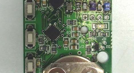
O8712865
Jul 07, 2014MINIATURE POCSAG UHF TRANSMITTER
Equipment Class
TNB - Licensed Non-Broadcast Station Transmitter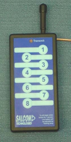
O871185
Jun 30, 2004UHF Pocket Paging Transmitter
Equipment Class
TNT - Licensed Non-Broadcast Transmitter Worn on Body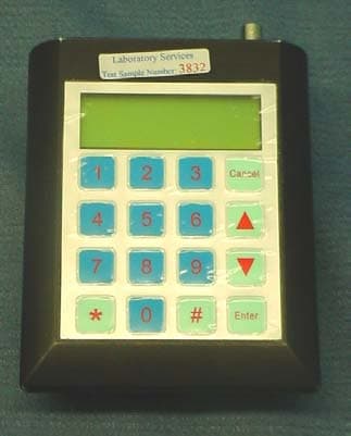
O871285
Jun 30, 2004UHF Desktop Paging Transmitter
Equipment Class
TNB - Licensed Non-Broadcast Station Transmitter