O9DAP5Wireless Activity Monitor
FitLinxx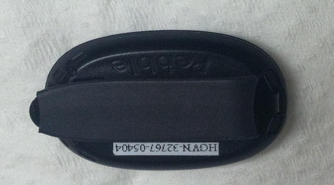
Click to zoom
Application Details
- Equipment Class
- DXX - Part 15 Low Power Communication Device Transmitter
- Date of Grant
- Jun 10, 2012
- Application Purpose
- Original Equipment
- Date of Application
- Jun 10, 2012
- Equipment Note
- Wireless Activity Monitor
- Frequency Range
- 2429.00000000 - 2429.00000000
- Company
- FitLinxx
- Country
- United States
Documents & Files
Document Text
Text extracted from the exhibit documents filed with the FCC. Open a document above to read the original.
Users Manual
Pebble Label Model: Pebble The FCC and the IC labels are engraved permanently on the bottom cover of the Pebble. Compliance Information FCC Notice to users The Pebble complies with Part 15 of the FCC Rules. Operation is subject to the following conditions: (1) this device may not cause harmful interference and (2) this device must accept any interference received, including interference that may cause undesired operation. CAUTION: Changes or modifications not expressly approved by the party responsible for compliance could void the user’s authority to operate the device. Industry Canada Notice to users This device complies with Industry Canada license-exempt RSS standard(s). Operation is subject to the following two conditions: (1) this device may not cause interference, and (2) this device must accept any interference, including interference that may cause undesired operation of the device. Le présent appareil est conforme aux CNR d'Industrie Canada applicables aux appareils radio exempts de licence. L'exploitation est autorisée aux deux conditions suivantes : (1) l'appareil ne doit pas produire de brouillage, et (2) l'utilisateur de l'appareil doit accepter tout brouillage radioélectrique subi, même si le brouillage est susceptible d'en compromettre le fonctionnement European Wireless EU Declaration of Conformity: This wireless device complies with the specification EN 300 440-2, EN 301-489 and EN 60950 following the provisions of the R&TTE Directive. © 2012 FitLinxx. All rights reserved. FitLinxx, the Fitlinxx logo, and Pebble are trademarks of FitLinxx, Inc.
ID Label/Location Info
.215.283 1.1429.075 1.2732.344 MATTE FINISH ON CAVITY SIDE NOTES (UNLESS OTHERWISE SPECIFIED): 3D CAD DATABASE CONTROLS PART GEOMETRY. REFER TO 3D CAD GEOMETRY FOR ANY PART DIMENSION NOT EXPLICITLY AND COMPLETELY DEFINED BY DRAWING DIMENSIONS. FITLINXX DESIGN APPROVAL REQUIRED BEFORETHE START OF PRODUCTION MOLD FABRICATION, TO INCLUDE: GATE AND EJECTOR PIN LOCATIONS,• PARTING LINE LOCATION,• DRAFT DEVIATIONS FROM 3D CAD GEOMETRY.• ALL SURFACES FREE FROM TOOLING MARKS.• REVCHANGED BYDATEDESCRIPTION m P EXCEPT AS NOTED, ALL DIMS ARE MM DIMENSIONS IN [ ] ARE INCHES This document contains confidential or proprietary information of FitLinxx. Neither this document nor the information therein is to be reproduced, distributed, used or disclosed either in whole or in part, except as specifically authorized by FitLinxx. 507-00060-01 CASE BOTTOM ACTIPED 5 SHEET 1 OF 1 - Drawn by SolidWorks POLYCARBONATE REV SCALE:1:1 DSN'D PAPER SIZE DRAWING NUMBER MAT'L DRAWN CHK'D DATE 542 Westport Avenue 2nd Floor Norwalk, CT 06851 Phone: (203) 316-5151 e-mail: [email protected] JCD DRAWN DSN'D A DATE CHK'D SURFACE FINISH: 3.2 ASME Y14.5M-1994 APPLIES 0 PLACE DECIMAL ANGULAR TOL'S 1 PLACE DECIMAL ± 0.25 mm ± 1.0 mm ± 1.0 2 PLACE DECIMAL ± 0.1 mm EWG JM - 1/23/2012 01 ®
Test Report
Test Report No. R-5586N-2 Retlif Testing Laboratories R Certification and Signatures We certify that these Test Results are true results obtained from the tests of the equipment stated, and relates only to the equipment tested. We further certify that the measurements shown in this Test Results package were made in accordance with the procedures indicated and vouch for the qualifications of all Retlif Testing Laboratories personnel taking them. Scott Wentworth Branch Manager NVLAP Approved Signatory Todd Hannamann Laboratory Supervisor iNARTE Certified ATL-0255-T Non-Warranty Provision The testing services have been performed, findings obtained and reports prepared in accordance with generally accepted laboratory principles and practices. This warranty is in lieu of all others, either expressed or implied. Non-Endorsement This test report contains only findings and results arrived at after employing the specific test procedures and standards listed herein. It is not intended to constitute a recommendation, endorsement or certification of the product or material tested. This test report may not be used by the client to claim product endorsement by NVLAP, NIST or any agency of the U.S. Government. Page 2 of 23 Test Report No. R-5586N-2 Retlif Testing Laboratories R Revision History Revisions to this document are listed below; the latest revised document supersedes all previous issues of this document. Revision Date Pages Affected - May 8, 2012 Original Release Page 3 of 23 Test Report No. R-5586N-2 Retlif Testing Laboratories R Test Program Summary Job Number: R-5586N-2 Applicant: FitLinxx Address: 134 Flanders Road, Suite 200 Westborough, MA 01581 Test Sample: Wireless Activity Device Brand Name: FitLinxx Model: Pebble Antenna Port/Type: No Antenna Port Internal Antenna - PCB Trace Power Requirements: 3 VDC Frequency Band of Operation: 2.40 GHz to 2.4835 GHz Frequency of Operation: 2.429 GHz FCC ID: O9DAP5 IC: 4068A-AP5 Test Specification: FCC Rules and Regulations Part 15, Subpart C, 15.249 Radio Standards Specification, RSS-210, Issue 8, December 2010 and RSS-GEN, Issue 3, December 2010 Test Procedure: ANSI C63.4: 2003, American National Standard for Methods of Measurement of Radio Noise Emissions from Low-Voltage Electrical and Electronic Equipment in the Range of 9 kHz to 40 GHz Purpose: The purpose of this test program was to demonstrate compliance of the Pebble Wireless Activity Device to the technical requirements of FCC Part 15.249 and RSS-210, Annex A2.9. Page 4 of 23 Test Report No. R-5586N-2 Retlif Testing Laboratories R Test Methods: The following table depicts the test methods that were performed on the EUT and the corresponding test results: Testing Date(s) FCC Part 15, Subpart C Industry Canada RSS-210 Issue 8, December 2010 Industry Canada RSS-GEN Issue 3, December 2010 Test Method Test Results April 20, 2012 15.249 (a) (e) A2.9 (a) N/A Field Strength of Fundamental & Harmonic Emissions Complied April 20, 2012 15.249 (d) A2.9 (b) N/A Field Strength of Out of Band/ Bandedge Emissions Complied April 20, 2012 N/A N/A 6.1 Field Strength of Receiver Spurious Emissions Complied April 24, 2012 N/A N/A 4.6.1 99% Bandwidth 3.86 MHz Test Sample Description: The Pebble Wireless Activity Device is a low power, narrowband 2.429 GHz wireless activity device. It consists of a sensor, microcontroller, radio transmitter/receiver, and a battery that can be worn on various parts of the body. The RF transmitter/receiver operates on a single channel. It transmits once per second with a sequenced dither to avoid RF collisions with other devices. The receiver is able to lock onto transmission so it can turn its RF receiver for the shortest period of time. The EUT is operated by 3 VDC via a single Lithium CR2032 battery. The EUT has no ports or attached cables. Support Equipment: The EUT did not require any support equipment. Test Sample/Test Results Summary: • The maximized fundamental field strength at 2429 MHz did not exceed 50 m V/M (94dBμV) at a test distance of 3 meters. The measured maximized average field strength was 79.7 dBμV. • The field strength of observed harmonic emissions did not exceed 500 μ V/M. No harmonic emissions were observed within 10dB of the specified limit at 3 meter or 1 meter test distances. • The field strength of non-harmonic out of band/bandedge emissions were attenuated more than 50dB below the level of the fundamental or to the limits of 15.209 as applicable. No out of band spurious emissions were observed within 10dB of the specified limit at 3 meter or 1 meter test distances. • The maximized peak field strength of the emissions did not exceed the maximum permitted average field strength by more than 20 dB. The measured maximized peak field strength was 82.68 dBμV. Page 5 of 23 Test Report No. R-5586N-2 Retlif Testing Laboratories R General Test Requirements 1. The measurement procedures of ANSI C63.4:2003 were utilized as specified in FCC Part 15, Subpart C, Section 15.31(a)(3) and RSS-Gen, Section 4.1. 2. All radiated emissions measurements were performed on an Open Area Test Site (OATS), listed with the FCC and IC, in accordance with FCC Section 15.31(d) and RSS Gen, Section 4.2. 3. All testing was performed with a new battery installed in the EUT, in accordance with FCC Section 15.31(e) and RSS Gen Section 4.3(g). 4. All measurements were performed at the specified 3 meter test distance. The EUT was rotated throughout 360 degrees for all radiated emissions measurements as specified in FCC Section 15.31(f)(5) and IC Section 4.3(h). 5. All readily accessible EUT controls were adjusted in such a manner as to maximize the level of emissions in accordance with FCC Section 15.31(g) and RSS-Gen, Section 4.3. 6. Appropriate accessories were attached to all EUT ports during the performance of radiated emissions measurements as required by FCC Section 15.31(i) and RSS-Gen, Section 4.3(f). 7. The EUT operated at the frequency of 2429.0 MHz. Testing was performed with t…
Text truncated - open the document above for the full version.
Test Setup Photos
Test Report No. R-5586N-2 Retlif Testing Laboratories R Test Setup Photographs Page 10 of 23 Test Report No. R-5586N-2 Retlif Testing Laboratories R Test Setup Photograph(s) Radiated Emissions Test Setup Page 11 of 23 Test Report No. R-5586N-2 Retlif Testing Laboratories R Test Setup Photograph(s) Radiated Emissions 30 to 1000 MHz, Horizontal Antenna Polarization 30 to 1000 MHz, Vertical Antenna Polarization Page 12 of 23 Test Report No. R-5586N-2 Retlif Testing Laboratories R Test Setup Photograph(s) Radiated Emissions 1 to 18 GHz, Horizontal Antenna Polarization 1 to 18 GHz, Vertical Antenna Polarization Page 13 of 23 Test Report No. R-5586N-2 Retlif Testing Laboratories R Test Setup Photograph(s) Radiated Emissions 18 to 26 GHz, Horizontal Antenna Polarization 18 to 26 GHz, Vertical Antenna Polarization Page 14 of 23 Test Report No. R-5586N-2 Retlif Testing Laboratories R Test Setup Photograph(s) 99% Bandwidth Test Setup Page 15 of 23
Contact Information
Applicant
John E MacLean(Vice President of Manufacturing)
Technical Contact
Retlif Testing LaboratoriesScott Wentworth
[email protected]6034974600
101 New Boston Road · Goffstown, New Hampshire · United States
Non-Technical Contact
Retlif Testing LaboratoriesScott Wentworth
[email protected]6034974600
Test Firm
Retlif Testing LaboratoriesScott Wentworth
Technical Specifications
| # | Rule Parts | Frequency Range | Power Output |
|---|---|---|---|
| 1 | 15C | 2.43 GHz - 2.43 GHz | - |
Other Applications from FitLinxx
O9DA
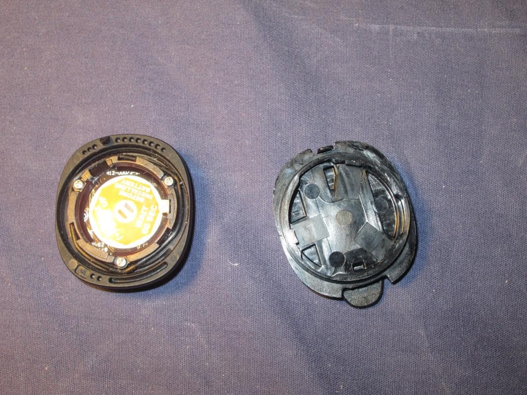
Dec 18, 2014Bluetooth Activity Sensor
Equipment Class
DXX - Part 15 Low Power Communication Device Transmitter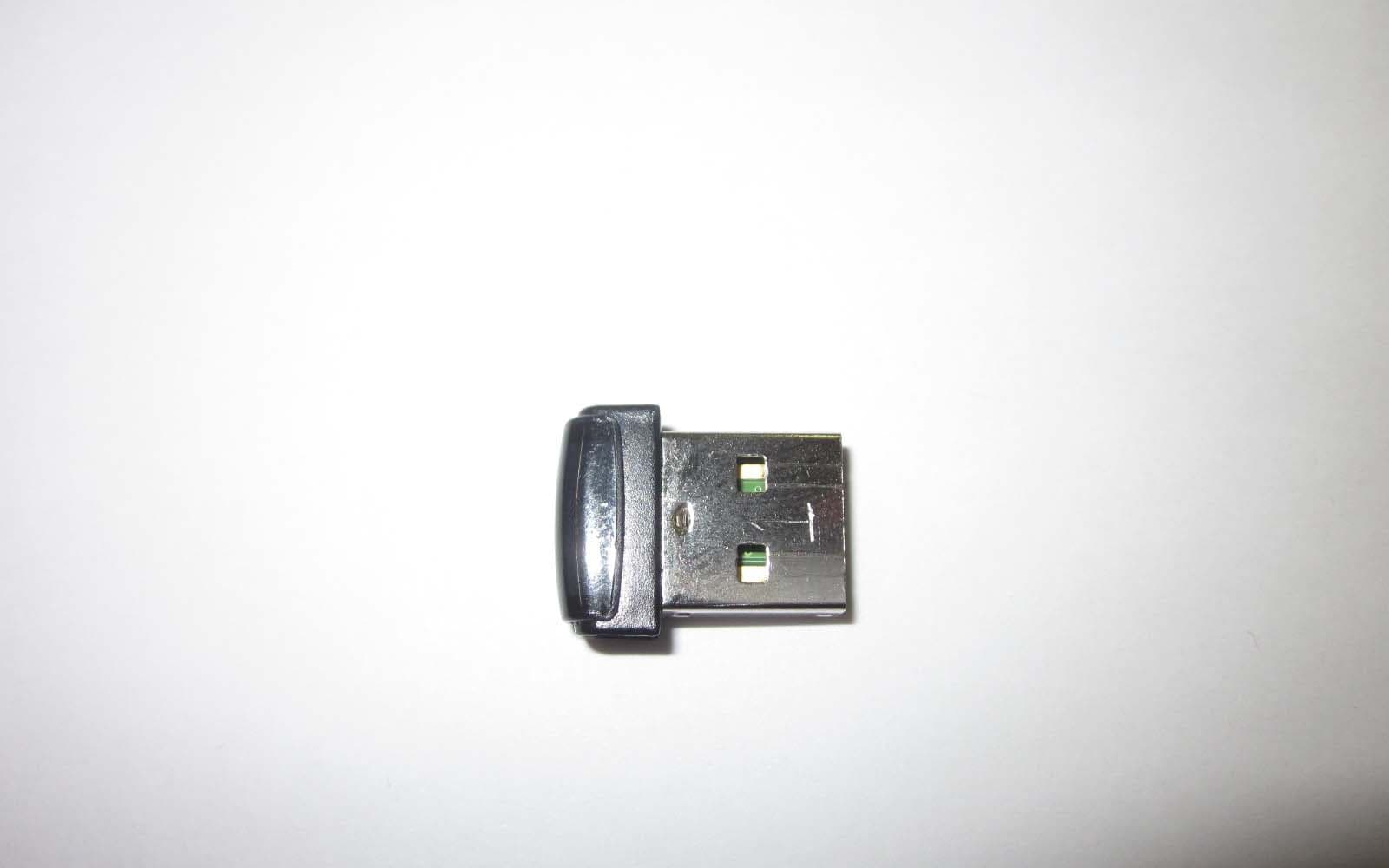
O9DAL3
Nov 20, 2012Wireless Access Point
Equipment Class
DXX - Part 15 Low Power Communication Device Transmitter
O9DIRB
Dec 05, 2011Alere AirLink for INRatio
Equipment Class
DTS - Digital Transmission System
O9DAP4
Feb 09, 2011Wireless Step Sensor/Pedometer
Equipment Class
DXX - Part 15 Low Power Communication Device Transmitter
O9DAP
Feb 20, 2008ActiPed Step Sensor/Pedometer Transceiver
Equipment Class
DXX - Part 15 Low Power Communication Device Transmitter