O9EM1213GMS/ GPRS Modem
Sierra Wireless, ULC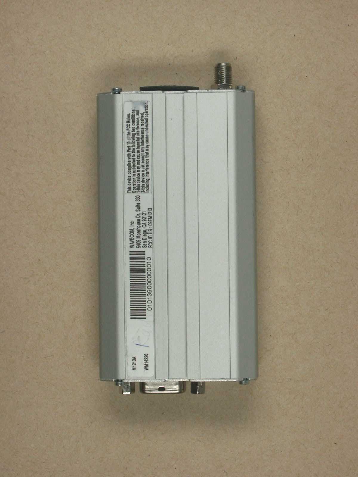
Click to zoom
Application Details
- Equipment Class
- PCB - PCS Licensed Transmitter
- Date of Grant
- Feb 18, 2003
- Application Purpose
- Original Equipment
- Date of Application
- Feb 18, 2003
- Equipment Note
- GMS/ GPRS Modem
- Frequency Range
- 1850.00000000 - 1910.00000000
- Company
- Sierra Wireless, ULC
- Country
- Canada
Documents & Files
Document Text
Text extracted from the exhibit documents filed with the FCC. Open a document above to read the original.
Users Manual
Fastrack M1200 series User Guide Reference : WM_MKT_Fastrack_UGD_001 Revision : 002 Date : September 2002 confidential © Page : 1 / 29 This document is the sole and exclusive property of WAVECOM. Not to be distributed or divulged without prior written agreement. Ce document est la propriété exclusive de WAVECOM. Il ne peut être communiqué ou divulgué à des tiers sans son autorisation préalable. WM_MKT_Fastrack_UGD_001 - 002 September 2002 Document Information Revision Date History of the evolution 001 June 02 Creation 002 Sept 02 Complete Revision confidential © Page : 2 / 29 This document is the sole and exclusive property of WAVECOM. Not to be distributed or divulged without prior written agreement. Ce document est la propriété exclusive de WAVECOM. Il ne peut être communiqué ou divulgué à des tiers sans son autorisation préalable. WM_MKT_Fastrack_UGD_001 - 002 September 2002 Overview This document describes the hardware interface and the technical specifications of the Fastrack M1200 series modems: • M1203 : EGSM/GPRS 900/1800 MHz version. • M1213 : EGSM/GPRS 900/1900 MHz version. These products are based on dual-band WISMO module and are GPRS class 2 capable. WAVECOM ® and WISMO ® are trademarks or registered trademarks of Wavecom S.A. in France or in other countries. All other company and/or product names mentioned may be trademarks or registered trademarks of their respective owners. WAVECOM S.A. may, at any time and without notice, make changes or improvements to the products and services offered and/or cease producing or commercializing them. confidential © Page : 3 / 29 This document is the sole and exclusive property of WAVECOM. Not to be distributed or divulged without prior written agreement. Ce document est la propriété exclusive de WAVECOM. Il ne peut être communiqué ou divulgué à des tiers sans son autorisation préalable. WM_MKT_Fastrack_UGD_001 - 002 September 2002 Contents 1 Product description..................................................................................................................................................................7 2 Product details...........................................................................................................................................................................7 2.1 Physical characteristics...............................................................................................................7 2.2 Electrical characteristics..............................................................................................................8 2.2.1 Power Consumption.......................................................................................................9 2.2.2 Audio interface.............................................................................................................10 2.3 GSM features.............................................................................................................................10 2.4 Hardware interfaces...................................................................................................................11 2.4.1 Connectors...................................................................................................................11 2.4.1.1 SUB-D connector details......................................................................................12 2.4.1.2 Power supply connector.......................................................................................12 2.4.2 LED function.................................................................................................................13 2.4.3 External antenna..........................................................................................................13 2.4.4 SIM interface ................................................................................................................13 3 Accessories..............................................................................................................................................................................14 4 Testing the configuration of Fastrack............................................................................................................................15 5 Getting started with Fastrack...........................................................................................................................................16 5.1 Mounting Fastrack.....................................................................................................................16 5.2 Installing Fastrack modem......................................................................................................... 17 5.3 Verifying signal strength............................................................................................................17 5.4 Verifying network registration of the modem.............................................................................18 6 Troubleshooting failed transmission...............................................................................................................................19 6.1 Receiving “no carrier” message...............................................................................................19 6.2 Not connecting through the serial link.......................................................................................21 6.3 Receiving “error” message........................................................................................................ 22 7 RF exposure instructions....................................................................................................................................................24 8 Notice to OEM’s....................................................................................................................................................................25 9 NOTES ON SAFETY..............................................................................…
Text truncated - open the document above for the full version.
Cover Letter(s)
CONFIDENTIALITY FORM Federal Communication Commission Equipment Authorization Division, Application Processing Branch 7435 Oakland Mills Road Columbia, MD 21048 January 27th, 2003 TO WHOM IT MAY CONCERN Pursuant to Paragraphs §0.457 and 0.459 of the Commission's Rules (47 C.F.R.) and Section §552(b)(4) of the Freedom of Information Act, WAVECOM INC requests confidentiality for the following products: FCC ill Number Product FCC ill: 09EM1213 Title/Model Fastrack Modem M1213A For the product stated above, we request that the following information be held confidential: 1) Electrical Schematics of the Circuitry 2) Block Diagram 3) Operational description 4) Tuning Procedure No other items submitted as part of the equipment authorization filing process are deemed confidential. The above exhibits contain W A VECOM S.A. trade secrets and proprietary information that could be of benefit to our competitors regarding the design of our mobile handset. This material is not customarily available to the general public and we request that it be withheld from public inspection. If you have any questions, please feel free to contact me at the address shown below. Sincerely, --~ ...=; \e-.::=..- Olivier CLERC Integration Engineer W A VECOM Inc 4810 Eastgate mall, 2nd fl. SAN DIEGO, California 92121 Tel: (858) 362 0101 ext 108 Fax: (858) 558 5485
External Photos
ELECTRONIC TECHNOLOGY SYSTEMS DR.GENZ GMBH ETS Dr. Genz GmbH, GermanyRegistration number: G0M20209-7148-T-47Page 1 of 10 Appendix A. Pictures ELECTRONIC TECHNOLOGY SYSTEMS DR.GENZ GMBH ETS Dr. Genz GmbH, GermanyRegistration number: G0M20209-7148-T-47Page 2 of 10 ELECTRONIC TECHNOLOGY SYSTEMS DR.GENZ GMBH ETS Dr. Genz GmbH, GermanyRegistration number: G0M20209-7148-T-47Page 3 of 10 ELECTRONIC TECHNOLOGY SYSTEMS DR.GENZ GMBH ETS Dr. Genz GmbH, GermanyRegistration number: G0M20209-7148-T-47Page 4 of 10
ID Label/Location Info
FCC ID Label Sample
ID Label/Location Info
FCC ID Label Location information
Internal Photos
ELECTRONIC TECHNOLOGY SYSTEMS DR.GENZ GMBH ETS Dr. Genz GmbH, GermanyRegistration number: G0M20209-7148-T-47Page 5 of 10 ELECTRONIC TECHNOLOGY SYSTEMS DR.GENZ GMBH ETS Dr. Genz GmbH, GermanyRegistration number: G0M20209-7148-T-47Page 6 of 10 ELECTRONIC TECHNOLOGY SYSTEMS DR.GENZ GMBH ETS Dr. Genz GmbH, GermanyRegistration number: G0M20209-7148-T-47Page 7 of 10
RF Exposure Info
INSTALLATION AND INSTRUCTION MANUAL INCLUDING HUMAN EXPOSURE STATEMENT As required by § 2.1033(c)(3), here is a part of the User's Guide and Technical Manual" that describes modem features, installation, and operation. Also provided, on page 16 of our User’s Manual, is a statement addressing human exposure to radiofrequency radiation. This information is necessary to ensure that equipment installers, operators and users are made aware of the dangers of exposure to radiofrequency radiation and that the Modem is installed and operated in compliance with 47 CFR Part 24, Subpart E of the FCC Rules and Regulations. Pursuant to § 24.52 RF hazards, all emissions from the DTSA Modem, both fundamental and unwanted, are subject to the radiofrequency radiation exposure requirements given in § 1.1307(b), § 2.1091 and § 2.1093, as appropriate. For fixed transmitters, § 1.1307(b) requires the preparation of an Environmental Assessment (EA) if the transmitter would cause human exposure to levels of radiofrequency radiation in excess of the applicable limits given in § 1.1310. However, determination of compliance with these limits and preparation of an EA if they are exceeded is required only for licensed PCS facilities, operations and transmitters with the following characteristics: 1. non-building-mounted antennas: height above ground level to lowest point of antenna < 10m and total power of all channels > 2000 W ERP (3280 W EIRP) 2. building-mounted antennas: total power of all channels > 2000 W (3280 W EIRP) "Fixed" in this context means that the device is physically secured at one location and is not able to be easily moved to another location. Since the modem transmits on a single channel with a maximum peak output power of 1.0 W (30 dBm) nominal, the maximum specified antenna gain of 7 dBi results in a maximum peak e.i.r.p. of 37 dBm (5.0 W), well below the level which would trigger a routine environmental evaluation. Therefore, in fixed applications, the modem is categorically excluded from performance of a routine environmental evaluation or preparation of an EA. In § 2.1091(b), a mobile device is defined as a transmitting device designed to be used in other than fixed locations and to generally be used in such a way that a separation distance of at least 20 centimeters is normally maintained between the transmitter's antenna and the body of the user or nearby persons. In accordance with § 2.1091(c), mobile PCS devices are categorically excluded from routine environmental evaluation for RF exposure prior to equipment authorization or use if their e.i.r.p. is less than 3 W (34.8 dBm). The Modem user’s manual requires a separation distance of at least 20 cm between the unit's antenna and the body of the user and nearby persons for all uses and applications, both mobile and fixed. Furthermore, for mobile applications, the maximum e.i.r.p. will not exceed 2 W (33 dBm), in accordance with the requirements of § 24.232(b). Therefore, for mobile applications, the modem is categorically excluded from a routine environmental evaluation for RF exposure. In all applications and uses, compliance with current FCC RF regulations limiting human exposure to radiofrequency exposure is dependent upon installation, operation and use of the equipment in accordance with all instructions provided. HUMAN EXPOSURE COMPLIANCE STATEMENT The following statement addressing human exposure to the RF energy emitted by the Modem is included in the “User's Manual." Pursuant to 47 CFR § 24.52 of the FCC Rules and Regulations, personal communications services (PCS) equipment is subject to the radiofrequency radiation exposure requirements specified in § 1.1307(b), § 2.1091 and § 2.1093, as appropriate. Wavecom, Inc. certifies that it has determined that the Modem complies with the RF hazard requirements applicable to broadband PCS equipment operating under the authority of 47 CFR Part 24, Subpart E of the FCC Rules and Regulations. This determination is dependent upon installation, operation and use of the equipment in accordance with all instructions provided. The Modem is designed for and intended to be used in fixed and mobile applications. "Fixed" means that the device is physically secured at one location and is not able to be easily moved to another location. "Mobile" means that the device is designed to be used in other than fixed locations and generally in such a way that a separation distance of at least 20 cm is normally maintained between the transmitter's antenna and the body of the user or nearby persons. The Modem is not designed for or intended to be used in portable applications (within 20 cm of the body of the user) and such uses are strictly prohibited. To ensure that the DTSA Modem complies with current FCC regulations limiting both maximum RF output power and human exposure to radiofrequency radiation, a separation distance of at least 20 cm must be maintained between the unit's antenna and the body of the user and any nearby persons at all times and in all applications and uses. Additionally, in mobile applications, maximum antenna gain must not exceed 3 dBi.
Test Report
ELECTRONIC TECHNOLOGY SYSTEMS DR. GENZ GMBH TEST - REPORT FCC RULES PART 24 Test report no.: G0M20209-7148-T-47 FCC ELECTRONIC TECHNOLOGY SYSTEMSSTORKOWER STRASSE 38C, D-15526 REICHENWALDE B. BERLIN DR. GENZ GMBHPHONE +49-33631-888 00 FAX +49-33631-888 66 ETS Dr. Genz GmbH, GermanyRegistration number: G0M20209-7148-T-47Page 1 of 21 ELECTRONIC TECHNOLOGY SYSTEMS DR.GENZ GMBH TABLE OF CONTENTS 1General information 1.1Notes 1.2Testing laboratory 1.3Details of approval holder 1.4Application details 1.5Test item 1.6Test standards 2Technical test 2.1Summary of test results 2.2Test environment 2.3Test equipment utilized 3 Test Results 4 RF Power Output, FCC 2.1046 4.1 Test Procedure 4.2 Test Results 5 Radiated Power, FCC 24.232 5.1 Test Procedure 5.2 Test Results 6 Occupied Bandwidth, FCC 2.1049 6.1 Test Procedure 6.2 Test Results 7 Field Strength of Spurious Radiations, FCC 2.1053, 24.238 7.1 Test Procedure 7.2 Test Results 8 Line Conducted Emissions, FCC 15.107 8.1 Test Procedure 8.2 Test Results 9 Frequency Stability vs Temperature, FCC 2.1055, 24.235 9.1 Test Procedure 9.2 Test Results 10 Frequency Stability vs Voltage, FCC 2.1055, 24.235 10.1 Test Procedure 10.2 Test Equipment ETS Dr. Genz GmbH, GermanyRegistration number: G0M20209-7148-T-47Page 2 of 21 ELECTRONIC TECHNOLOGY SYSTEMS DR.GENZ GMBH 1General Information 1.1Notes The purpose of conformity testing is to increase the probability of adherence to the essential requirements or conformity specifications, as appropriate. The complexity of the technical specifications, however, means that full and thorough testing is impractical for both technical and economic reasons. Furthermore, there is no guarantee that a test sample which has passed all the relevant tests conforms to a specification. Neither is there any guarantee that such a test sample will interwork with other genuinely open systems. The existence of the tests nevertheless provides the confidence that the test sample possesses the qualities as maintained and that is performance generally conforms to representative cases of communications equipment. The test results of this test report relate exclusively to the item tested as specified in 1.5. The test report may only be reproduced or published in full. Reproduction or publication of extracts from the report requires the prior written approval of the ELECTRONIC TECHNOLOGY SYSTEMS DR. GENZ GMBH. Tester: 13.12.2002Mr. Schulz DateETS-Lab.NameSignature Technical responsibility for area of testing: 13.12.2002Dr. Genz DateETSNameSignature ETS Dr. Genz GmbH, GermanyRegistration number: G0M20209-7148-T-47Page 3 of 21 ELECTRONIC TECHNOLOGY SYSTEMS DR.GENZ GMBH 1.2 Testing laboratory 1.2.1Location ELECTRONIC TECHNOLOGY SYSTEM DR. GENZ GMBH (ETS) Storkower Straße 38c D-15526 Reichenwalde b. Berlin Germany Telefon : +49 33631 888 00 Telefax : +49 33631 888 660 1.2.2Details of accreditation status A CCREDITED TESTING LABORATORY DAR-REGISTRATION NUMBER: TTI-P-G 126/96 ACCREDITED COMPETENT BODY DAR-REGISTRATION NUMBER: BPT-ZE-026/96 FCC FILED TEST LABORATORY REG. NO. 96970 BLUETOOTH QUALIFICATION TEST FACILITY (BQTF) ACCREDITED BY: BLUETOOTH QUALIFICATION REVIEW BOARD (BQRF) I NDUSTRY CANADA FILED TEST LABORATORY REG. NO. IC 3470 A2LA A CCREDITEDCertificate Number: 1983-01 1.3Details of approval holder Name: Wavecom Street: 12, boulevard Garibaldi Town: 92442 Issy Les Moulineaux Country: France Telephone: 33 1 46 29 08 00 Fax: 33 1 46 29 08 08 Contact: Mr. Pierre-Jean Severin Email: [email protected] ETS Dr. Genz GmbH, GermanyRegistration number: G0M20209-7148-T-47Page 4 of 21 ELECTRONIC TECHNOLOGY SYSTEMS DR.GENZ GMBH 1.4Application details Date of receipt of application: 05.11.2002 Date of receipt of test item: 05.11.2002 Date of test: 06.11.2002 – 07.11.2002 1.5Test item Description of test item: GSM/GPRS External Modem Type identification: M1213 Serial number: Test model without serial number. Photos: See annex A Technical data Frequency range Tx: 1850-1910 MHz Frequency range Rx: 1930-1990 MHz Antenna transmitter: Dual-band antenna: ALLGON 1140.26 Antenna Gain: 0 dBi (antenna + cable) Antenna and cable are a constructive unit. Power supply : 12,0 V DC Operating mode: duplex Type of modulation: GMSK (GSM modulation) Emission: GXW Manufacturer: (if applicable) Name: Wavecom Street: 12, boulevard Garibaldi Town: 92442 Issy Les Moulineaux Country: France Additional information: none ETS Dr. Genz GmbH, GermanyRegistration number: G0M20209-7148-T-47Page 5 of 21 ELECTRONIC TECHNOLOGY SYSTEMS DR.GENZ GMBH 1.6Test standards Technical standard : FCC Part 24 2Technical test 2.1Summary of test results No deviations from the technical specification(s) were ascertained in the course ý of the tests performed. or The deviations as specified in 2.5 were ascertained in the course of the tests ̈ performed. 2.2Test environment Temperature: 22 o C Relative humidity content: 20 ...75 % Air pressure: 86 ...103 kPa Extreme temperature: -30 / 60 °C ETS Dr. Genz GmbH, GermanyRegistration number: G0M20209-7148-T-47Page 6 of 21 ELECTRONIC TECHNOLOGY SYSTEMS DR.GENZ GMBH 2.3Test equipment utilized No.Measurement device:Type:Manufacturer: ETS 0001Test receiverESHS 10Rohde&Schwarz ETS 0002Test receiverESVPRohde&Schwarz ETS 0003Test receiverESVS 10Rohde&Schwarz ETS 0004Spectrum- and Network-AnalyzerFSMS 26Rohde&Schwarz ETS 0005Test receiverSMV 11MEB ETS 0006Test receiver systemSME 12MEB ETS 0007Spectrum analyzerPSA-65AAvcom ETS 0008AntennaLoop antennaSiemens ETS 0009AntennaLoop antennaMEB ETS 0010AntennaLoop antennaMEB ETS 0011Antennavan Veen/ FrameETS ETS 0012AntennaHK 116Rohde&Schwarz ETS 0013AntennaHL 223Rohde&Schwarz ETS 0014AntennaHL 025Rohde&Schwarz ETS 0015AntennaHL 025Rohde&Schwarz ETS 0016AntennaVHAPSchwarzbeck ETS 0017AntennaVHAPSchwarzbeck ETS 0018AntennaUHAPSchwarzbeck ETS 0019AntennaUHAPSchwarzbeck ETS 0020AntennaDP 21MEB ETS 0021AntennaDP 3MEB ETS 0022AntennaSAS-200/ 521A.H. Systeme / USA ETS 0023AntennaDP 1MEB ETS 0024Antenna mastAF 2MEB ETS…
Text truncated - open the document above for the full version.
Test Report
FASTRACK M1213: ALLGON 1140.27 ANTENNA SPECIFICATION
Test Report
EMI voltage test in the ac-mains according to FCC part 15 EUT:GSM/GPRS EXTERNAL MODEM / M1213 Manufacturer:WAVECOM INC. Operating Condition:Unom: 120VAC(AC/DC-adaptor), Tnom: 23°C Test Site:ETS Operator:Mr. Pflug Test Specification:V-Network: ESH2-Z5 (L1) Comment:model: M1213 mode: channel 62, powerlevel 5 -10 0 10 20 30 40 50 60 70 Level [dBμV] 150k300k500k1M2M3M 4M6M10M30M Frequency [Hz] MES FCCp15_norm_pre PK MES FCCp15_norm_pre AV LIM FCCp15_QP_01 Voltage QP Limit LIM FCCp15_AV_01 Voltage AV Limit Page 1/1 13.02.03 10:47 FCCp15_norm EMI voltage test in the ac-mains according to FCC part 15 EUT:GSM/GPRS EXTERNAL MODEM / M1213 Manufacturer:WAVECOM INC. Operating Condition:Unom: 120VAC, Tnom: 23°C Test Site:ETS Operator:Mr. Pflug Test Specification:V-Network: ESH2-Z5 (N) Comment:model: M1213 mode: channel 62, powerlevel 5 -10 0 10 20 30 40 50 60 70 Level [dBμV] 150k300k500k1M2M3M 4M6M10M30M Frequency [Hz] MES FCCp15_norm_pre PK MES FCCp15_norm_pre AV LIM FCCp15_QP_01 Voltage QP Limit LIM FCCp15_AV_01 Voltage AV Limit Page 1/1 13.02.03 11:30 FCCp15_norm
Test Setup Photos
ELECTRONIC TECHNOLOGY SYSTEMS DR.GENZ GMBH ETS Dr. Genz GmbH, GermanyRegistration number: G0M20209-7148-T-47Page 11 of 13
Test Setup Photos
ELECTRONIC TECHNOLOGY SYSTEMS DR.GENZ GMBH ETS Dr. Genz GmbH, GermanyRegistration number: G0M20209-7148-T-47Page 8 of 10 ELECTRONIC TECHNOLOGY SYSTEMS DR.GENZ GMBH ETS Dr. Genz GmbH, GermanyRegistration number: G0M20209-7148-T-47Page 9 of 10 ELECTRONIC TECHNOLOGY SYSTEMS DR.GENZ GMBH ETS Dr. Genz GmbH, GermanyRegistration number: G0M20209-7148-T-47Page 10 of 10
Contact Information
Applicant
Ying Wang(Staff Regulatory Specialist)
Test Firm
Eurofins Product Service GmbHRobert Kschiwan-Kaspar
Technical Specifications
| # | Rule Parts | Frequency Range | Power Output | Emission | Tolerance |
|---|---|---|---|---|---|
| 1 | 24E | 1.85 GHz - 1.91 GHz | 867.00 mW | 316KGXW | 0.1000000000 ppm |
Other Applications from Sierra Wireless, ULC
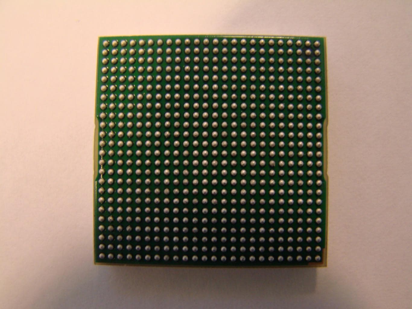
O9EWMP100
Apr 09, 2007Quadband GSM Module
Equipment Class
PCB - PCS Licensed Transmitter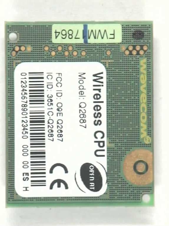
O9EQ2687
Nov 07, 2006Wireless CPU (850/900/1800/1900 MHz)
Equipment Class
PCB - PCS Licensed Transmitter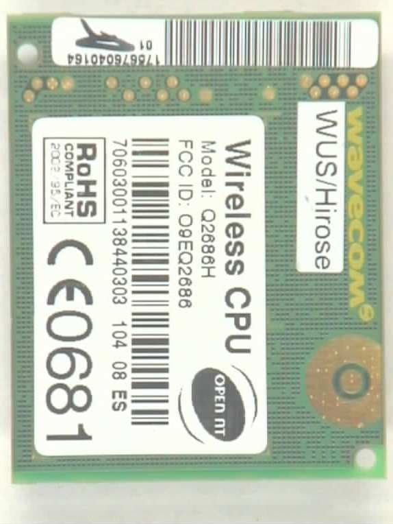
O9EQ2686
Apr 27, 2006Q2686
Equipment Class
PCB - PCS Licensed Transmitter
O9EQ2438F-M
Jun 05, 2005TRI MODE CDMA WIRELESS MODULE KIT
Equipment Class
PCB - PCS Licensed Transmitter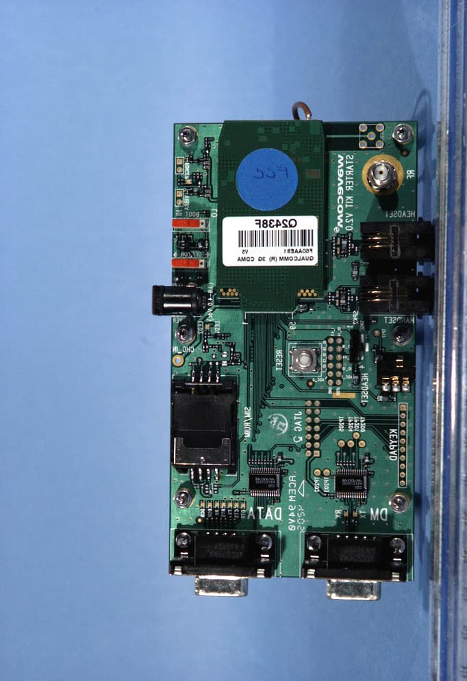
O9EQ2438F
May 13, 2004Tri-Mode Dual-Band CDMA Wireless Evaluation Kit
Equipment Class
PCB - PCS Licensed Transmitter