O9EM2113GSM Modem
Sierra Wireless, ULC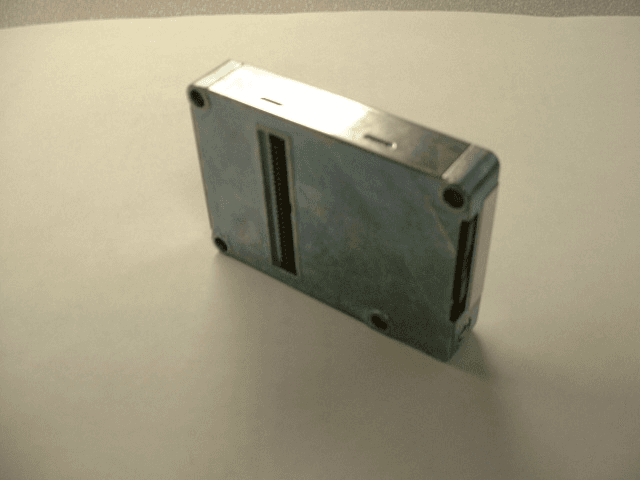
Click to zoom
Application Details
- Equipment Class
- PCB - PCS Licensed Transmitter
- Date of Grant
- Apr 23, 2002
- Application Purpose
- Original Equipment
- Date of Application
- Apr 23, 2002
- Equipment Note
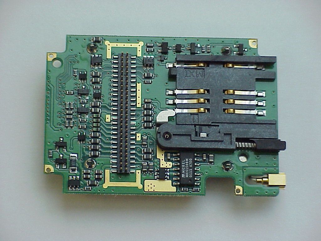
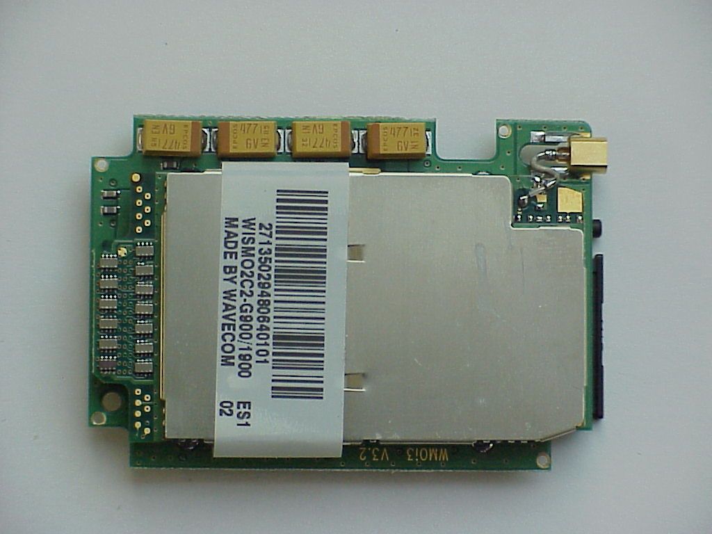
- GSM Modem
- Frequency Range
- 1850.20000000 - 1909.80000000
- Company
- Sierra Wireless, ULC
- Country
- Canada
Documents & Files
Document Text
Text extracted from the exhibit documents filed with the FCC. Open a document above to read the original.
Users Manual
March 2002/ version 1.6 Integra Version : 1.7 Date : March 2002 Reference : WM_Integra_UG_016 confidential © 1/60 This document is the sole and exclusive property of WAVECOM. Not to be distributed or divulged without prior written agreement. Ce document est la propriété exlcusive de WAVECOM. Il ne peut être communiqué ou divulgué à des tiers sans son autorisation préalable. March 2002/ version 1.6 Integra Level/ Indice Date/ Date History of the evolution / Historique des évolutions Writer / Rédacteur 0.3 June 2000 Creation and Correction P. Calvez, S. Dechicha F. Doherier, T. Lapousterle, M. Nau, D. Martinez, B. Zenou 1.2 Sept. 2000 Correction: figure 5 application note for serial link S. Dechicha 1.3 Sept 2000 Application note for external SIM 3V/5V interface S. Dechicha 1.4 January 2001 Minor formal modifications + addition of the mechanical specifications M. Nau 1.5 August 2001 SIM3/5V electric scheme added + modification flat cable reference S. Marion 1.6 March 2002 Modifications to include 2C-2 module version N. Subiger 1.7 March 2002 Add RF exposure and OEM instructions O. Clerc Name / Nom Function / Fonction Date/ Date Signature/ Signature Written by / Rédigé par B.Zenou Product Marketing June 2000 Validated by / Validé par D. MARTINEZ Modem Support Engineer June 2000 Approved by / Approuvé par P.Calvez Product Marketing Senior Manager June 2000 confidential © 2/60 This document is the sole and exclusive property of WAVECOM. Not to be distributed or divulged without prior written agreement. Ce document est la propriété exlcusive de WAVECOM. Il ne peut être communiqué ou divulgué à des tiers sans son autorisation préalable. March 2002/ version 1.6 Integra Integra User’s Guide Hardware Specifications confidential © 3/60 This document is the sole and exclusive property of WAVECOM. Not to be distributed or divulged without prior written agreement. Ce document est la propriété exlcusive de WAVECOM. Il ne peut être communiqué ou divulgué à des tiers sans son autorisation préalable. March 2002/ version 1.6 Integra Contents 1 Introduction to the Integra: outstanding assets........................................................................................................................7 1.1 Scope of the user’s guide............................................................................................................7 1.2 General characteristics................................................................................................................8 1.2.1 General.....................................................................................................................................8 1.2.2 Electrical...................................................................................................................................8 1.2.3 Physical....................................................................................................................................8 1.2.4 Basic Features..........................................................................................................................8 1.2.5 Interfaces..................................................................................................................................9 1.3 Mechanical Design Overview....................................................................................................10 2 Safety precautions..................................................................................................................................................................................13 2.1 RF safety....................................................................................................................................13 2.1.1 General...................................................................................................................................13 2.1.2 Exposure to RF energy...........................................................................................................13 2.1.3 Efficient modem operation......................................................................................................13 2.1.4 Antenna care and replacement..............................................................................................13 2.2 General safety...........................................................................................................................14 2.2.1 Driving.....................................................................................................................................14 2.2.2 Electronic devices...................................................................................................................14 2.2.3 Vehicle electronic equipment.................................................................................................14 2.2.4 Medical electronic equipment.................................................................................................14 2.2.5 Aircraft....................................................................................................................................14 2.2.6 Children..................................................................................................................................14 2.2.7 Blasting areas.........................................................................................................................14 2.2.8 Potentially explosive atmospheres.........................................................................................15 2.3 Safety standards........................................................................................................................15 3 Standard Compliance............................................................................................................................................................................15 3.1 GSM compliance.........................................................................................…
Text truncated - open the document above for the full version.
Attestation Statements
ctc_gn_01_00.doc (General);4/24/02Page 1 of 1 CETECO M Inc. 411 Dixon Landing Road Milpitas, CA 95035 U. S . A. Phone: + 1 408 586 6200 Fax: + 1 408 586 6299 e-mail: [email protected] UR L: www .c etec om.c om To whom it concerns FCC ID: O9EM2113 Wavecom is submitting this application for a modularized transmitter to be operated in the 1850 to 1910 MHz band. It is intended to be used as a fixed or mobile transmitter to be integrated into a variety of products to provide wireless access to a PCS network. The module is a dual band transmitter intended to operate in the European GSM cellular network and the PCS American network using GSM protocols. Since the GSM cellular network is not available in the US, the device cannot be operated at this frequency in the US. Application examples include but are not limited to: data acquisition for mobile products, fleet management, meter reading, theft protection, emergency calls, and alarm devices where separation distance between the transmitter and the user is specified to be 20 cm or more. This device is not intended to be used in portable products as defined in Section 2.1093 of the FCC Rules. For purposes of RF Exposure requirements, it is intended for mobile and fixed use only as defined in Section 2.1091 of the FCC Rules. Further, manufacturers and installers are warned that the maximum gain of the antenna that is attached to the devices is limited to 3.0 dBi yielding an EIRP of 2 watts or less for mobile use and 7 dBi for fixed use. Please see the attachments for further information regarding this requirement. The module contains its own power supply regulator, data interfaces and buffering and is completely shielded by its own case. Wavecom requires other manufacturers that are using this product to use an antenna with no more than 3 dBi gain for mobile applications and 7 dBi for fixed applications. The measurements were done with a test jig, which provided the interface to operate the device under test. This measure showed also the capability to fulfill all the requirements without the additional shielding from any host equipment. The reported radiated values are only informal since the antenna used will not be sold with the product. All references like RF exposure are based on the conducted measurements. Lothar Schmidt CETECOM Inc.
Cover Letter(s)
CONFIDENTIALITY FORM Federal Communication Commission Equipment Authorization Division, Application Processing Branch 7435 Oakland Mills Road Columbia, MD 21048 February 13, 2002 TO WHOM IT MAY CONCERN Pursuant to Paragraphs §0.457 and 0.459 of the Commission’s Rules (47 C.F.R.) and Section §552(b)(4) of the Freedom of Information Act, WAVECOM INC requests confidentiality for the following products: FCC ID Number Product Title/Model O9EM2113 Integrated Modem/Integra M2113A For the product stated above, we request that the following information be held confidential: 1) Electrical Schematics of the Circuitry 2) Block Diagram 3) Operational description No other items submitted as part of the equipment authorization filing process are deemed confidential. The above exhibits contain WAVECOM S.A. trade secrets and proprietary information that could be of benefit to our competitors regarding the design of our mobile handset. This material is not customarily available to the general public and we request that it be withheld from public inspection. If you have any questions, please feel free to contact me at the address shown below. Sincerely, Olivier CLERC Integration Engineer WAVECOM Inc 610 West Ash, suite 1400 SAN DIEGO, California 92101 Tel: (619) 235 9702 ext 108 Fax: (619) 235 9844
Parts List/Tune Up Info
Tune Up Procedure There is no tune-up procedure for this device, the power level is set at the factory and there are no provisions for a user to adjust the power level.
RF Exposure Info
CETECOM Inc. 411 Dixon Landing Road Milpitas, CA 95035 Federal Communication Commission Authorization and Evaluation Division 7435 Oakland Mills Road Columbia, MD 21046 Attention: Reviewing Engineer The Integra M2113A integrated GSM modem is designed and intended for mobile applications only. However, RF exposure compliance has been addressed for fixed applications in addition to mobile applications. Included in the users manual are definitions for fixed and portable applications and limitations on antenna gain as appropriate for each application to insure that end users and OEMs have been provided necessary information to permit them to avoid exceeding the RF exposure guidelines as provided in the Commission’s Rules. This information includes the following: 20 cm separation between the body and the antenna must be maintained, use in portable applications is prohibited for mobile applications the maximum antenna gain is 3 dBi, and for fixed applications the maximum antenna gain is 7 dBi. The factory tuning procedure ensures that the transmitter output power does not exceed 1 watt. Measured maximum for the unit tested was 712 milliwatts as measured during an interval of transmission. Sections 13 and 14 of the filed users manual address the various warnings and provide instructions to users and OEMs in order to make all parties aware of their responsibilities. Following the provided installation and operating requirements will ensure compliance with the MPE limits, regardless of application. Regarding MPE limits, GPUC environment limits maximum exposure to 1 mW/cm 2 . With 0.712 watts output and 7 dBi gain antenna this system produces a maximum power density of 0.711 mW/cm 2 at a distance of 20 cm. Calculations are based on standard formula for calculating field strength at a distance and converting to power density using free space impedance. Further, the device uses the GSM protocol which is a TDD format ratio of 1/8 in GSM mode and 2/8 in GPRS mode. Thus the 0.711 mWatts/cm 2 is further reduced by this ratio or it is equivalent to 0.178 mW/cm 2 for GPRS mode. If calculated with the max power possible of 1 W the values are 0.997 mW/cm 2 using the same TDD ratio for GPRS mode of 2/8 the actual maximum is 0.249 mW/cm 2. . Since compliance is shown for the worst case condition for the unintended application in a fixed application, compliance with MPE requirements for the mobile application with a maximum antenna gain of 3 dBi is assured under all conditions. Again, instructions to insure compliance with RF exposure requirements are provided for both the user and OEMs. These instructions will permit OEMs to provide the necessary information to the end users of their products in order to insure the end user is not exposed to electromagnetic radiation that exceeds the FCC limits. CETECOM Inc. 411 Dixon Landing Road Milpitas, CA 95035 Lothar Schmidt Technical Manager EMC/Radio
Test Report
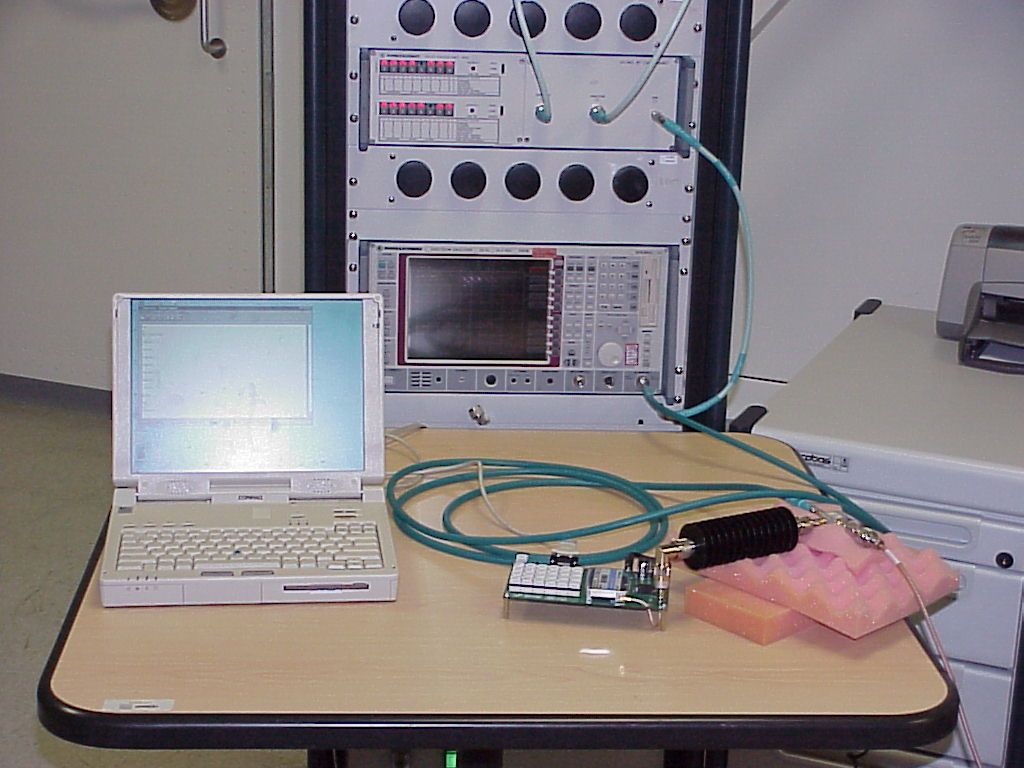
CETECOM Inc. CETECOM Inc. 411 Dixon Landing Road, Milpitas, CA-95035, USA Phone: +1 408 586 6200 Fax: +1 408 586 6299 www.cetecom.com Issued test report consists of 52 Pages Page 1 (52) Test report no.: 247FCC24/2002 FCC Part 24 / RSS 133 (INTEGRA M2113A) FCC LISTED, REG. NO.: 101450 & RECOGNIZED BY INDUSTRY CANADA IC – 3925 CETECOM Inc. Test report no.: 247FCC24/2002 Issue date: 2002-02-26 Page 2 (52) Table of Contents 1 General information 1.1 Notes 1.2 Testing laboratory 1.3 Details of applicant 1.4 Application details 1.5 Test item 1.6 Test standards 2 Technical test 2.1 Summary of test results 2.2 Test report 1 General information 1.1 Notes The test results of this test report relate exclusively to the test item specified in 1.5. The CETECOM Inc. does not assume responsibility for any conclusions and generalisations drawn from the test results with regard to other specimens or samples of the type of the equipment represented by the test item. The test report may only be reproduced or published in full. Reproduction or publication of extracts from the report requires the prior written approval of the CETECOM Inc. TEST REPORT PREPARED BY: EMC & Radio Engineer : Harpreet Sidhu 1.2 Testing laboratory CETECOM Inc. 411 Dixon Landing Road, Milpitas, CA-95035, USA Phone: +1 408 586 6200 Fax: +1 408 586 6299 E-mail: [email protected] Internet: www.cetecom.com CETECOM Inc. Test report no.: 247FCC24/2002 Issue date: 2002-02-26 Page 3 (52) 1.3 Details of applicant Name : Wavecom Inc. Street : 4810 Eastgate Mall, 2nd Fl City : San Diego, CA 92121 Country : USA Contact : Olivier Clerc Telephone : +1 858 362 0101 Tele-fax : +1 858 558 5485 e-mail : [email protected] 1.4 Application details Date of receipt of application : 2002-02-05 Date of receipt test item : 2002-02-11 Date of test : 2002-02-12 1.5 Test item Manufacturer : Wavecom S.A Street : 12 Boulevard Garibaldi City : Issy Les Moulineaux Cedex, 92442 Country : France Model No : INTEGRA M2113A Description : Integrated Modem 900/1900 MHz GSM 16/2Mb Serial No. : Prototype Additional information Frequency : 1850.2MHz – 1909.8MHz Type of modulation : GMSK Number of channels : 299 in PCS Antenna : External Power supply : 5VDC Output power : 28.53 dBm (712mW) (conducted power) Extreme vol. Limits : 4.75VDC – 5.25VDC Extreme temp. Tolerance : -30ºC to +50ºC 1.6 Test standards FCC Part 24 / RSS133 r1 CETECOM Inc. Test report no.: 247FCC24/2002 Issue date: 2002-02-26 Page 4 (52) 2 Technical test 2.1 Summary of test results No deviations from the technical specification(s) were ascertained in the course of the tests performed. Technical responsibility for area of testing : 2002-02-26 EMC & Radio Lothar Schmidt Date Section Name Signature CETECOM Inc. Test report no.: 247FCC24/2002 Issue date: 2002-02-26 Page 5 (52) 2.2 Test report TEST REPORT Test report no.: 247FCC24/2002 (INTEGRA M2113A) CETECOM Inc. Test report no.: 247FCC24/2002 Issue date: 2002-02-26 Page 6 (52) TEST REPORT REFERENCE LIST OF MEASUREMENTS PARAMETER TO BE MEASURED PARAGRAPH PAGE POWER OUTPUT SUBCLAUSE § 24.232 7 FREQUENCY STABILITY SUBCLAUSE § 24.235 12 OCCUPIED BANDWIDTH SUBCLAUSE § 2.989 14 EMISSION LIMITS SUBCLAUSE § 24.238 21 RECEIVER RADIATED EMISSIONS SUBCLAUSE § 15.209 38 CONDUCTED SPURIOUS EMISSIONS SUBCLAUSE § 24.238 43 AC LINE CODUCTED EMISSIONS SUBCLAUSE § 15.107/207 48 TEST EQUIPMENT LISTING 50 BLOCK DIAGRAMS 51 CETECOM Inc. Test report no.: 247FCC24/2002 Issue date: 2002-02-26 Page 7 (52) POWER OUTPUT SUBCLAUSE § 24.232 Summary: During the process of testing, the EUT was controlled via Rhode & Schwarz Digital Radio Communication tester (CMD-55) to ensure max. power transmission and proper modulation. This paragraph contains both average, peak output powers and EIRP measurements for the EUT. In all cases, the peak output power is within the required mask (this mask is specified in the JTC standards, TIA PN3389 Vol. 1 Chap 7, and is no FCC requirement). Method of Measurements: The EUT was set up for the max. output power with pseudo random data modulation. The power was measured with R&S Spectrum Analyzer FSEM 30 ( peak and average) This measurements were done at 3 frequencies, 1850.2 MHz, 1880.0 MHz and 1909.8 MHz (bottom, middle and top of operational frequency range) Limits: Power Step Nominal Peak Output Power (dBm) Tolerance (dB) 0 +30 ± 2 Power Measurements: Conducted: Frequency (MHz) Power Step Peak Output Power (dBm) Average Output Power (dBm) 1850.2 0 28.21 24.21 1880.0 0 28.53 24.31 1909.8 0 28.46 24.26 Measurement uncertainty ±0.5 dB ANALYZER SETTINGS: RBW = 3MHz VBW = 3MHz CETECOM Inc. Test report no.: 247FCC24/2002 Issue date: 2002-02-26 Page 8 (52) EIRP Measurements Description: This is the test for the maximum radiated power from the EUT. Rule Part 24.232(b) specifies that "Mobile/portable stations are limited to 2 watts e.i.r.p. peak power" and 24.232(c) specifies that "Peak transmit power must be measured over any interval of continuous transmission using instrumentation calibrated in terms of an rms-equivalent voltage." Method of Measurement: 1. In an anechoic antenna test chamber, a half-wave dipole antenna for the frequency band of interest is placed at the reference centre of the chamber. An RF Signal source for the frequency band of interest is connected to the dipole with a cable that has been constructed to not interfere with the radiation pattern of the antenna. A known (measured) power (Pin) is applied to the input of the dipole, and the power received (Pr) at the chamber's probe antenna is recorded. 2. A "reference path loss" is established as Pin + 2.1 - Pr. 3. The EUT is substituted for the dipole at the reference centre of the chamber. The EUT is put into CW test mode and a scan is performed to obtain the radiation pattern. 4. From the radiation pattern, the co-ordinates where the maximum antenna gain occurs is identified. 5. The EUT is then put into pulse mode at its maximum power level (Power Step 0). 6. "Gated mode…
Text truncated - open the document above for the full version.
Contact Information
Applicant
Ying Wang(Staff Regulatory Specialist)
Technical Contact
CETECOM Inc.Lothar Schmidt
[email protected]408-586-6214
411 Dixon Landing Road · Milpitas, California · United States
Non-Technical Contact
CETECOM Inc.Lothar Schmidt
[email protected]408-586-6214
Test Firm
Cetecom Inc.Lothar Schmidt
Technical Specifications
| # | Rule Parts | Frequency Range | Power Output | Emission | Tolerance |
|---|---|---|---|---|---|
| 1 | 24E | 1.85 GHz - 1.91 GHz | 712.00 mW | 330KGXW | 0.0170000000 ppm |
Other Applications from Sierra Wireless, ULC
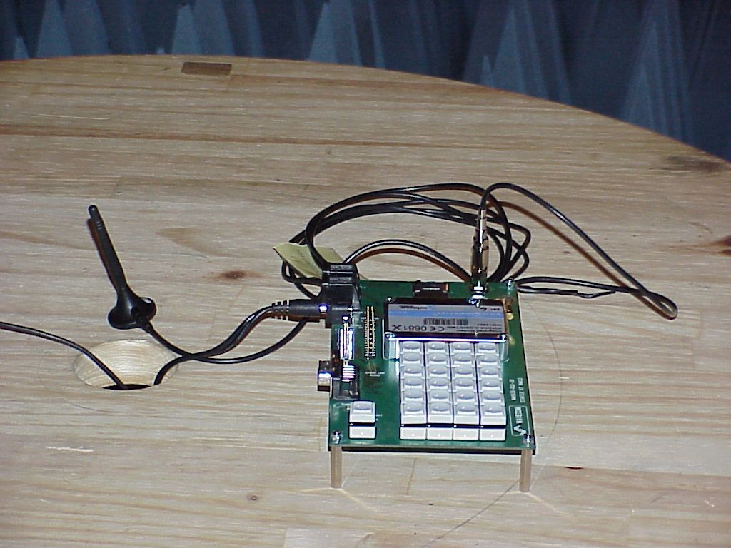
O9EWMP100
Apr 09, 2007Quadband GSM Module
Equipment Class
PCB - PCS Licensed Transmitter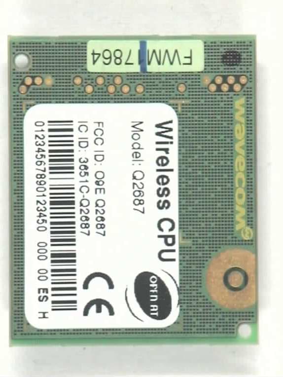
O9EQ2687
Nov 07, 2006Wireless CPU (850/900/1800/1900 MHz)
Equipment Class
PCB - PCS Licensed Transmitter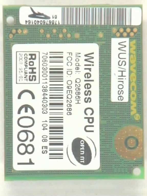
O9EQ2686
Apr 27, 2006Q2686
Equipment Class
PCB - PCS Licensed Transmitter
O9EQ2438F-M
Jun 05, 2005TRI MODE CDMA WIRELESS MODULE KIT
Equipment Class
PCB - PCS Licensed Transmitter
O9EQ2438F
May 13, 2004Tri-Mode Dual-Band CDMA Wireless Evaluation Kit
Equipment Class
PCB - PCS Licensed Transmitter