O9EWMOD2B-G0919Transmitter module for mobile applications
Sierra Wireless, ULC
Click to zoom
Application Details
- Equipment Class
- TNB - Licensed Non-Broadcast Station Transmitter
- Date of Grant
- Jul 02, 2001
- Application Purpose
- Original Equipment
- Date of Application
- May 12, 2001
- Equipment Note
- Transmitter module for mobile applications
- Frequency Range
- 1850.20000000 - 1909.20000000
- Company
- Sierra Wireless, ULC
- Country
- Canada
Documents & Files
Document Text
Text extracted from the exhibit documents filed with the FCC. Open a document above to read the original.
Users Manual
WMOD2B dual-band 900/1800 or 900/1900 MHz modem USER MANUAL Wavecom WMOD2B Modem SUMMARY 1. PRODUCT DESCRIPTION1 1.1 Package content1 1.2 Product presentation1 1.3 Physical characteristics2 1.4 Functions - GSM Modes2 1.5 Temperature range2 2. INSTALLATION/START-UP3 2.1 Mounting the modem3 2.2 Installing the modem3 2.3 Electrical characteristics4 2.3.1 Switching the GSM modem on/off4 2.3.2 Voltage range4 2.3.3 Overvoltage/undervoltage4 2.3.4 Power supply cable5 2.3.5 Input/output electrical characteristics defined for all external connections6 2.3.6 Protection/on-board network connection6 3. DESCRIPTION OF THE INTERFACES7 3.1 LED Function7 3.2 Connectors7 4. TECHNICAL DATA11 SUMMAR Y Wavecom WMOD2B Modem 5. TROUBLESHOOTING : Specific defaults possibly encountered12 5.1 The modem does not answer through the serial link12 5.2 The modem always returns «Error» when trying to issue a communication13 5.3 The modem always returns «No carrier» when trying to issue a communication14 1.4 Functions - GSM Modes2 1.5 Temperature range2 6. REFERENCE ACCESSORIES16 7.1 General safety16 7.2 Vehicle safety17 7.3 Car And Maintenance17 7.4 Your responsibility18 8. GENERAL INFORMATIONS19 SUMMAR Y 1Wavecom WMOD2B Modem 1. PRODUCT DESCRIPTION The Wavecom WMOD2B modem exists under two dual-band versions: - EGSM 900/1800 MHz - EGSM 900/1900 MHz 1.1Package content The Wavecom WMOD2B modem package comprises: - 1 Modem - 2 holding bridles - 1 Power supply cable + fuse - 1 User manual (this document) 1.2Product presentation The Wavecom WMOD2B modem supports DATA and FAX transmission, Short Messages (Point to Point and Cell Broadcast) and VOICE calls. The connectors binded to the body guarantee output and input connections. An extractible holder is used to insert the SIM card (Micro-SIM type). A LED indicates the operating mode. PRODUCT DESCRIPTION Micro-Fit TM connector SUB HD connector Front cap LED Extractible SIM holder SMA connector Back cap Figure 1 Modem presentation 2Wavecom WMOD2B Modem 1.3Physical characteristics 1.4Functions - GSM Modes 1.5Temperature range Operating conditions:From -20°C to +55°C Storage conditions:From -25°C to +70°C PRODUCT DESCRIPTION Dimensions98x54x25 mm (excluding connectors) Overall dimensions110x54x25 mm Weight< 130 grams Volume13.23 cm 3 HousingAluminium profiled StandardDual Band Extended GSM 900 MHz Class 4 (2W) and GSM 1800/1900 MHz Class 1 (1W) InterfaceSerial interface RS232 V.24/V.28 Autobauding function ATcommand set based on V.25ter and GSM 07.05 & 07.07 Mobile Originated (MO) and Mobile Terminated (MT). SMSMode Text & PDU point to point.Cell broadcast. In accordance with GSM 07.05. Asynchronous 2400, 4800, 9600 and 14400 bits/s. Data Transparent and Non Transparent mode. In Non Transparent Mode only: 300, 1200, 1200/75 bauds. Mode 3.1 KHz (PSTN) and V110 (ISDN). 2400/4800/7200/9600 bits/s FaxGSM teleservice 62 in Transparent Mode. Class 2. Groupe 3 compatible. AudioHalf Rate / Full Rate / Enhanced Full Rate.Accessories (options): handset and car-kit. 3Wavecom WMOD2B Modem INST ALLA TION/ST AR T -UP 2 INSTALLATION/START-UP 2.1Mounting the modem For mounting the modem, bind to the body the holding bridles according to the schema below: 2.2Installing the modem To install the modem, plug the device on a DC power supply (for automotive applications, connect the device on the permanent« + » and insert the SIM card in the holder). Make sure that an antenna is connected. In order to extract or to insert the Micro SIM card, it is necessary to press the SIM holder ejector with a sharp element (a pen for example). If this sequence is not respected, the SIM holder could be damaged. 2 mm Holding bridles Figure 2 Modem mounting Note: - To be attached to a plain surface - Screw head max. height: 2mm 4Wavecom WMOD2B Modem INST ALLA TION/ST AR T -UP 2.3Electrical characteristics 2.3.1Switching the GSM modem on/off The device is permanently powered (when connected to the power supply). 2.3.2Voltage range Voltage range:5 to 32V DC GND:0V 2.3.3Overvoltage/undervoltage Correct operation of the Wavecom WMOD2B modem in communication mode is not guaranteed if input voltage fall below 5V. The modem is protected against voltage over 32V. When input voltages exceed 32V, the supply voltage is disconnected in order to protect the electronic components from an overvoltage. TWO CASES ARE POSSIBLE: - IF THE OVERVOLTAGE IS CONTINUOUS, THE PROTECTION IS GUARANTEED BY THE FUSE. - IN THE CASE OF TRANSIENT PEAKS, THE MODEM GUARANTEES ITS OWN PROTECTION. 5Wavecom WMOD2B Modem INST ALLA TION/ST AR T -UP 2.3.4Power supply cable A cable, included in the package shall be used for power supply connection. The wires are marked as follows: Cable:1 wire Ame:tinned copper 24x0.2 mm Section:0.75 mm 2 Figure 3 Power supply cable + - Side view Connector Molex Micro-Fit 3.0 TM Cables stripped over 200 mm, protected by their own sheath Standard cable sheath Stripped wire, tinned over 5 mm 6Wavecom WMOD2B Modem INST ALLA TION/ST AR T -UP 2.3.5Input/output electrical characteristics defined for all external connections 2.3.6Protection/on-board network connection The modem is protected by a fuse directly binded on the power supply cable. Parameters GSM 900 MINTYPMAXMINTYPMAX GSM 1800/1900 UNIT Power supply @25°C: Input supply voltage513.232513.232V @5V1.81.1A @13.2V0.70.4A @32V0.40.2A @5V330220mA @13.2V13095mA @32V6550mA @5V31.431.4mA @13.2V13.213.2mA @32V5.65.6mA @5V8.88.8mA @13.2V4.14.1mA @32V2.22.2mA Serial link : - RS232 Audio (head set): Microphone input voltage @ lowest gain.43.843.82mVrms Speaker output voltage @ maximum gain.1.651.65Vrms Speaker impedance3232Ω SIM3 or 53 or 5V Input peak supply current (in communication @ Pmax) Input average supply current (in communication @ Pmax) Input average supply current in idle mode Input average supply current in idle mode (with auto-shutdown of the RS232 driver)* * RS232 driver (MAX3238) automatically shutdown after 30s of inactivity on the serial link. The tests are carried …
Text truncated - open the document above for the full version.
Cover Letter(s)
June 19, 2001 CONFIDENTIALITY REQUEST Federal Communications Commission Authorization and Evaluation Division 7435 Oakland Mills Road Columbia, MD 21046 Re:Wavecom application for certification of a Licensed Non-Broadcast Transmitter FCC ID: O9EWMOD2B-G0919 Gentlemen: Wavecom herein submits an Application for Equipment Authorization to be followed by submission of a fee for $640.00 along with Form 159 for certification of a licensed non-broadcast transmitter under FCC Rules Part 24 as required by the FCC Rules. Wavecom requests, pursuant to 47CFR 0.459, post grant confidentiality for portions of the material contained in this application such that the identified material will be withheld from public inspection following the grant of this authorization. This material, as indicated by request for confidentiality of the item during the electronic submission process and further identified below, includes: 1. Circuit diagrams submitted as Equipment Authorization Electronic Filing attachment: "schematics" to the application file. 2. Parts List submitted as an Equipment Authorization Electronic Filing attachment: “parts list” to the application file. 3. PCB board layout &RF Block Diagram submitted as an Equipment Authorization Electronic Filing attachment: “pcblayout” & "RF Block Diagram" to the application file. Specifically, these exhibits contain information relating to circuit function and complexity that could be of benefit to competitors. The material contains trade secrets and confidential information that Wavecom does not customarily release to the public and which is otherwise not generally available to the public. Please contact the undersigned by phone at 410-531-3439, by fax at 410-531-0807, by email at [email protected], or by correspondence at the address below if there are any further questions or additional information needed concerning this filing. Regards, (signed) Phillip Inglis, 14085 Howard Rd. Dayton, MD. 21036
External Photos
CETECOM Inc. Test report no.: 142FCC/2001 Issue date: 2001.05.10 Page 47 (53) PHOTOGRAPHS OF THE EQUIPMENT Photograph no.: 1
Internal Photos
CETECOM Inc. Test report no.: 142FCC/2001 Issue date: 2001.05.10 Page 50 (53) Photograph no.: 4 CETECOM Inc. Test report no.: 142FCC/2001 Issue date: 2001.05.10 Page 51 (53) Photograph no.: 5 CETECOM Inc. Test report no.: 142FCC/2001 Issue date: 2001.05.10 Page 52 (53) Photograph no.: 6 CETECOM Inc. Test report no.: 142FCC/2001 Issue date: 2001.05.10 Page 53 (53) Photograph no.: 7
Operational Description
1Wavecom WMOD2B Modem 1. PRODUCT DESCRIPTION The Wavecom WMOD2B modem exists under two dual-band versions: - EGSM 900/1800 MHz - EGSM 900/1900 MHz 1.1Package content The Wavecom WMOD2B modem package comprises: - 1 Modem - 2 holding bridles - 1 Power supply cable + fuse - 1 User manual (this document) 1.2Product presentation The Wavecom WMOD2B modem supports DATA and FAX transmission, Short Messages (Point to Point and Cell Broadcast) and VOICE calls. The connectors binded to the body guarantee output and input connections. An extractible holder is used to insert the SIM card (Micro-SIM type). A LED indicates the operating mode. PRODUCT DESCRIPTION Micro-Fit TM connector SUB HD connector Front cap LED Extractible SIM holder SMA connector Back cap Figure 1 Modem presentation 2Wavecom WMOD2B Modem 1.3Physical characteristics 1.4Functions - GSM Modes 1.5Temperature range Operating conditions:From -20°C to +55°C Storage conditions:From -25°C to +70°C PRODUCT DESCRIPTION Dimensions98x54x25 mm (excluding connectors) Overall dimensions110x54x25 mm Weight< 130 grams Volume13.23 cm 3 HousingAluminium profiled StandardDual Band Extended GSM 900 MHz Class 4 (2W) and GSM 1800/1900 MHz Class 1 (1W) InterfaceSerial interface RS232 V.24/V.28 Autobauding function ATcommand set based on V.25ter and GSM 07.05 & 07.07 Mobile Originated (MO) and Mobile Terminated (MT). SMSMode Text & PDU point to point.Cell broadcast. In accordance with GSM 07.05. Asynchronous 2400, 4800, 9600 and 14400 bits/s. Data Transparent and Non Transparent mode. In Non Transparent Mode only: 300, 1200, 1200/75 bauds. Mode 3.1 KHz (PSTN) and V110 (ISDN). 2400/4800/7200/9600 bits/s FaxGSM teleservice 62 in Transparent Mode. Class 2. Groupe 3 compatible. AudioHalf Rate / Full Rate / Enhanced Full Rate.Accessories (options): handset and car-kit.
RF Exposure Info
1 Memorandum To: FCC Examiner/Engineer From: Phillip Inglis, Cetecom bvba/Agent for Wavecom Date: 05/13/2001 Re : FCC ID:O9EWMOD2B-G0919 This is a supplement to address additional issues related to the pending application for the referenced FCC ID:O9EWMOD2B-G0919, related to RF exposure requiremens for FCC certification. This device is designed and intended for mobile applications only. However, RF exposure compliance has been addressed for fixed applications in addition to mobile applications. Included in the users manual are definitions for fixed and portable applications and limitations on antenna gain as appropriate for each application to insure that end users and OEMs have been provided necessary information to permit them to avoid exceeding the RF exposure guidelines as provided in the Commission’s Rules. This information includes the following: 20 cm separation between the body and the antenna must be maintained, use in portable applications is prohibited, for mobile applications the maximum antenna gain is 3 dBi, and for fixed applications the maximum antenna gain is 7 dBi. The factory tuning procedure ensures that the transmitter output power does not exceed 1 watt. Measured maximum for the unit tested was 851 milliwatts as measured during an interval of transmission. Sections 6 and 7 of the revised and filed users manual described as “Users Manual with Addendum” address the various warnings and provide instructions to users and OEMs in order to make all parties aware of their responsibilities. Following the provided installation and operating requirements will ensure compliance with the MPE limits, regardless of application. Regarding MPE limits, GPUC environment limits maximum exposure to 1 mW/cm 2 . Wit h 0.873 watts output and 7 dBi gain antenna for fixed applications (numerical ratio = 5) this system produces a maximum power densit y of 0.868 mWatts/cm 2 at a distance of 20 cm. Calculations are based on standard formula for calculating field strength at a distance and converting to power density using free space impedance. Further, the device uses the GSM protocol which is a TDD format ratio of 1/8. Thus the 0.868 mWatts/cm 2 is further reduce d by this ratio or it is equivalent to 0.109 mWatt s/cm2. Since compliance is shown for the worst case condition for the unintended application in a fixed application, compliance with MPE requirements for the mobile application with a maximum antenna gain of 3 dBi is ass ured. This analysis is based on conducted measured power. Again, instructions to insure compliance with RF exposure requirements are provided for both the user and OEMs. These instructions will permit OEMs to provide the necessary information to the May 13, 2001 2 end users of their products in order to insure the end user is not exposed to electromagnetic radiation that exceeds the FCC limits. Phillip Inglis, Cetecom bvba/ Agent for Wavecom.
Test Report
CETECOM Inc. CETECOM Inc. 411 Dixon Landing Road, Milpitas, CA-95035, USA Phone: +1 408 586 6200 Fax: +1 408 586 6299 www.cetecomusa.com Issued test report consists of 53 Pages Page 1 (53) RECOGNIZED BY INDUSTRY CANADA IC-3925 Test report no.: 142FCC/2001 FCC Part 24 FCC ID: 09EWMOD2B-G0919 CETECOM Inc. Test report no.: 142FCC/2001 Issue date: 2001.05.10 Page 2 (53) Table of Contents 1 General information 1.1 Notes 1.2 Testing laboratory 1.3 Details of applicant 1.4 Application details 1.5 Test item 1.6 Test standards 2 Technical test 2.1 Summary of test results 2.2 Test report 1 General information 1.1 Notes The test results of this test report relate exclusively to the test item specified in 1.5. The CETECOM Inc. does not assume responsibility for any conclusions and generalisations drawn from the test results with regard to other specimens or samples of the type of the equipment represented by the test item. The test report may only be reproduced or published in full. Reproduction or publication of extracts from the report requires the prior written approval of the CETECOM Inc. 1.2 Testing laboratory CETECOM Inc. 411 Dixon Landing Road, Milpitas, CA-95035, USA Phone: +1 408 586 6200 Fax: +1 408 586 6299 E-mail: [email protected] Internet: www.cetecomusa.com CETECOM Inc. Test report no.: 142FCC/2001 Issue date: 2001.05.10 Page 3 (53) 1.3 Details of applicant Name : Wavecom Inc. Street Add.: 610 West Ash., Suite 1400 City/State : San Diego, CA-92101 Country : USA Telephone : +1 619 235 9702 Telefax : +1 619 235 9844 Contact : Hatim Limati e-mail : [email protected] Telephone : +1 619 235 9702 1.4 Application details Date of receipt of application : 2001-04-08 Date of receipt of test item : 2001-04-15 Date of test : 2001-04-17/19 1.5 Test item Manufacturer : Name of EUT : Description : Wavecom SA WMOD2B 900/1900 External Modem GSM 900/1900 Model No. : WMOD2B 900/1900 Serial number : FCC ID : Prototype 09EWMOD2B-G0919 Additional information Frequency : E GSM/PCS Type of modulation : GSM Number of channels : GSM 174, PCS 299 Antenna : external Antenna Power supply : 12VDC Output power : 1 Watt EUT Temp. Tolerance : Temperature range : -30°C - +60°C EUT Extreme Vol. Range : 5VDC to 32VDC 1.6 Test standards FCC Part 24 CETECOM Inc. Test report no.: 142FCC/2001 Issue date: 2001.05.10 Page 4 (53) 2 Technical test 2.1 Summary of test results No deviations from the technical specification(s) were ascertained in the course of the tests performed. Technical responsibility for area of testing : 2001-05-10 EMC& Radio Lothar Schmidt Date Section Name Signature CETECOM Inc. Test report no.: 142FCC/2001 Issue date: 2001.05.10 Page 5 (53) 2.2 Test report TEST REPORT Test report no.: 142FCC/2001 FCC ID: 09EWMOD2B-G0919 CETECOM Inc. Test report no.: 142FCC/2001 Issue date: 2001.05.10 Page 6 (53) TEST REPORT REFERENCE LIST OF MEASUREMENTS PARAMETER TO BE MEASURED Paragraph PAGE POWER OUTPUT SUBCLAUSE § 24.232 7 FREQUENCY STABILITY SUBCLAUSE § 24.235 12 EMISSIONS LIMITS §24.238 14 RECEIVER SPURIOUS EMISSIONS §15.209 25 CONDUCTED SPURIOUS EMISSIONS 29 OCCUPIED BANDWIDTH §2.989 36 CONDUCTED EMISSIONS § 15.107/207 43 TEST EQUIPMENT AND ANCILLARIES USED FOR TESTS 44 TEST SITE 45 PHOTOGRAPHS OF THE EQUIPMENT 47 CETECOM Inc. Test report no.: 142FCC/2001 Issue date: 2001.05.10 Page 7 (53) POWER OUTPUT SUBCLAUSE § 24.232 Summary: This paragraph contains both average , peak output powers and EIRP measurements for the EUT. In all cases, the peak output power is within the required mask (this mask is specified in the JTC standards, TIA PN3389 Vol. 1 Chap 7, and is no FCC requirement). Method of Measurements: The EUT was set up for the max. output power with pseudo random data modulation. The power was measured with R&S Spectrum Analyzer FSEM 30 ( peak and average) This measurements were done at 3 frequencies, 1850.2 MHz, 1880.0 MHz and 1909.8 MHz (bottom, middle and top of operational frequency range) Limits: Power Step Nominal Peak Output Power (dBm) Tolerance (dB) 0 +30 ± ±± ± 2 Power Measurements: Conducted: Frequency (MHz) Power Step Peak Output Power (dBm) Average Output Power (dBm) 1850.2 0 29.29 20.00 1880.0 0 29.41 20.12 1909.8 0 29.29 20.00 Measurement uncertainty ± ±± ±0.5 dB CETECOM Inc. Test report no.: 142FCC/2001 Issue date: 2001.05.10 Page 8 (53) EIRP Measurements Description: This is the test for the maximum radiated power from the EUT. Rule Part 24.232(b) specifies that "Mobile/portable stations are limited to 2 watts e.i.r.p. peak power..." and 24.232(c) specifies that "Peak transmit power must be measured over any interval of continuous transmission using instrumentation calibrated in terms of an rms-equivalent voltage." Method of Measurement: 1. In an anechoic antenna test chamber, a half-wave dipole antenna for the frequency band of interest is placed at the reference center of the chamber. An RF Signal source for the frequency band of interest is connected to the dipole with a cable that has been constructed to not interfere with the radiation pattern of the antenna. A known (measured) power (Pin) is applied to the input of the dipole, and the power received (Pr) at the chamber's probe antenna is recorded. 2. A "reference path loss" is established as Pin + 2.1 - Pr. 3. The EUT is substituted for the dipole at the reference center of the chamber. The EUT is put into CW test mode and a scan is performed to obtain the radiation pattern. 4. From the radiation pattern, the co-ordinates where the maximum antenna gain occurs is identified. 5. The EUT is then put into pulse mode at its maximum power level (Power Step 0). 6. "Gated mode" power measurements are performed with the receiving antenna placed at the coordinates determined in Step 3 to determine the output power as defined in FCC Rule 24.232 (b) and (c). The "reference path loss" from Step 1 is added to this result. 7. This value is EIRP since the measurement is calibrated using a half-wave dipole antenna of known gain (2.…
Text truncated - open the document above for the full version.
Test Setup Photos
CETECOM Inc. Test report no.: 142FCC/2001 Issue date: 2001.05.10 Page 45 (53) TEST SITE RADIATED EMISSIONS CETECOM Inc. Test report no.: 142FCC/2001 Issue date: 2001.05.10 Page 46 (53) EUT in Climatic Chamber
Contact Information
Applicant
Ying Wang(Staff Regulatory Specialist)
Technical Contact
TRP/Cetecom bvbaPhillip Inglis
[email protected]4105313439
14085 Howard Rd · Dayton, Maryland · United States
Non-Technical Contact
TRP/Cetecom bvbaPhillip Inglis
[email protected]4105313439
Test Firm
Cetecom ICT Services GmbHRalf Hoehn
Technical Specifications
| # | Rule Parts | Frequency Range | Power Output | Emission | Tolerance |
|---|---|---|---|---|---|
| 1 | 24E | 1.85 GHz - 1.91 GHz | 1 W | 315KGXW | 0.1000000000 ppm |
Other Applications from Sierra Wireless, ULC
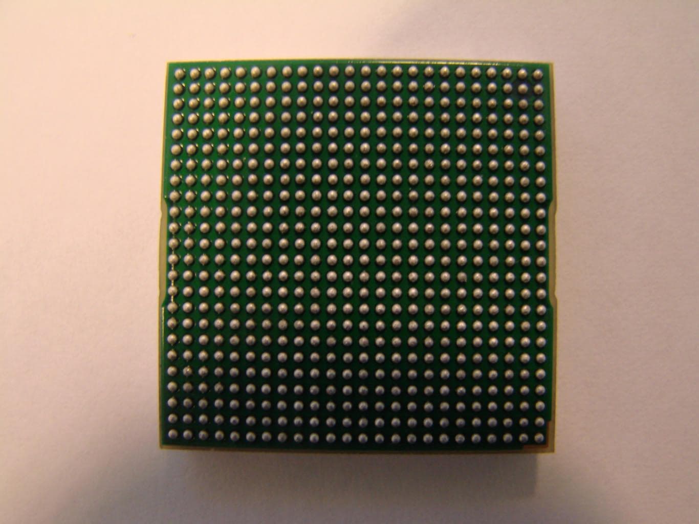
O9EWMP100
Apr 09, 2007Quadband GSM Module
Equipment Class
PCB - PCS Licensed Transmitter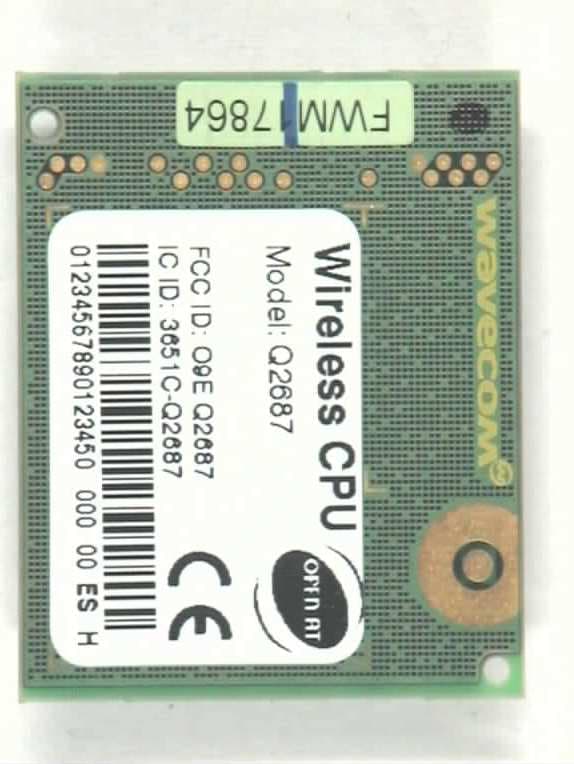
O9EQ2687
Nov 07, 2006Wireless CPU (850/900/1800/1900 MHz)
Equipment Class
PCB - PCS Licensed Transmitter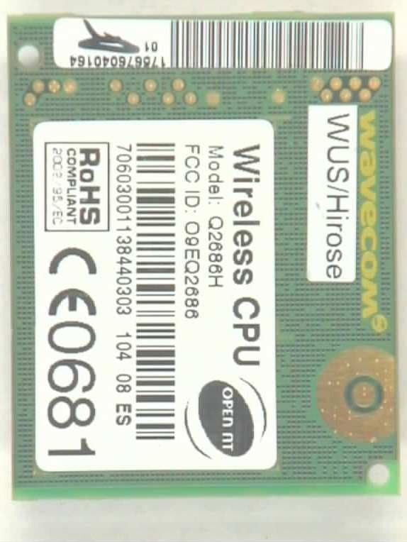
O9EQ2686
Apr 27, 2006Q2686
Equipment Class
PCB - PCS Licensed Transmitter
O9EQ2438F-M
Jun 05, 2005TRI MODE CDMA WIRELESS MODULE KIT
Equipment Class
PCB - PCS Licensed Transmitter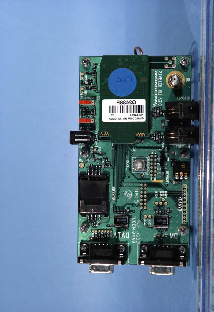
O9EQ2438F
May 13, 2004Tri-Mode Dual-Band CDMA Wireless Evaluation Kit
Equipment Class
PCB - PCS Licensed Transmitter