OAYARS100-2Vehicle Radar System
Automotive Distance Control Systems GmbHApplication Details
- Equipment Class
- FDS - Part 15 Field Disturbance Sensor
- Date of Grant
- Apr 23, 2002
- Application Purpose
- Original Equipment
- Date of Application
- Nov 04, 2001
- Equipment Note
- Vehicle Radar System
- Frequency Range
- 76000.00000000 - 77000.00000000
- Country
- Germany
Documents & Files
Document Text
Text extracted from the exhibit documents filed with the FCC. Open a document above to read the original.
Users Manual
133 Multifunction steering wheel, multifunction display Technical data Instruments and controls Operation Driving Instrument cluster display Practical hints Car care Index Distronic (DTR) 1 Distronic is deactivated. The actual distance (5) and the should-be distance (6) to the vehicle ahead (4) are displayed. 2 Activating Distronic. The display with the selected speed is shown for approximately 5 seconds . 3 Distronic is activated. The message “DTR OFF” appears for approximately 5 seconds when Distronic is being deactivated . 4 Vehicle ahead. Only appears if a vehicle is detected ahead. 5 Actual distance to vehicle ahead. 6 Should-be distance to vehicle ahead (as calculated by Distronic). 7 Own vehicle. 8 Distance warning function is activated, see page 271. Press the è or ÿ button repeatedly until the required system is displayed.Distronic (DTR) see page 260.Pressing the è or ÿ button displays the next or previous system. part2_01.fm Seite 133 Montag, 7. Mai 2001 7:06 07 260 Driving systems Technical data Instruments and controls Operation Driving Instrument cluster display Practical hints Car care Index Distronic (DTR)(optional)When activated the Distronic system increases driving convenience, for example over long distances, as it automatically maintains a speed set by the driver by actively regulating the throttle setting. It also maintains within certain limitations a preset distance to a vehicle ahead.With Distronic switched off, the multifunction display continues to show the distance to the vehicle ahead, if so selected, see page 274. The distance warning function can be activated separately, see page 271.In Distronic mode, if the distance sensor detects a slower moving vehicle directly ahead, your vehicle speed will be reduced to the extent permitted by reduced throttle and up to 20% of vehicle braking power, so that you follow that vehicle at a preset distance, see page 272.Maximum range of detection is approximately 500 ft. (150 m). Any given speed between 25 mph (Canada: 30 km/h) and 110 mph (Canada: 180 km/h) can be maintained with the Distronic by operating the control lever on the steering column. Warning!Distronic is a convenience system, its speed adjustment reduction capability is intended to make cruise control more effective and usable when traffic speeds vary. It is not, however, intended to nor does it replace the need for extreme care. The responsibility for the vehicle speed and the distance to the vehicle ahead, including most importantly brake operation to assure safe stopping distance, rests always with the driver.Warning!Distronic requires familiarity with its operational characteristics. We strongly recommend that you review the following information carefully before operating the system. part3_01.fm Seite 260 Montag, 7. Mai 2001 7:05 07 261 Driving systems Technical data Instruments and controls Operation Driving Instrument cluster display Practical hints Car care Index Note:For operation in the USA only: This device complies with Part 15 of the FCC Rules. Operation is subject to the following two conditions:(1) This device may not cause harmful interference, and(2) this device must accept any interference received, including interference that may cause undesired operation.Any unauthorized modification to this device could void the user’s authority to operate the equipment. Warning!Only use Distronic if the traffic and weather conditions make it advisable to travel at a steady speed.Use of Distronic can be dangerous on winding roads or in heavy traffic because conditions do not allow safe driving at a steady speed.Use of Distronic can be dangerous on slippery roads. Rapid changes in tire adhesion can result in wheel spin and loss of control.Distronic does not act upon adverse sight distance conditions. Do not use Distronic during conditions of fog and heavy rain, snow or sleet.The “Resume” function should only be operated if the driver is fully aware of the previously set speed and wishes to resume this particular preset speed.Distronic does not recognize accordingly and will not react to stationary objects. It is designed and intended only to maintain a set speed and keep a set distance from moving objects in front of it. part3_01.fm Seite 261 Montag, 7. Mai 2001 7:05 07 262 Driving systems Technical data Instruments and controls Operation Driving Instrument cluster display Practical hints Car care Index The speed stored in memory is displayed in the multifunction display, and one or two segments around the stored speed light up in the speedometer dial, see page 275. 1 Accelerate and set:To increase the speed by 5 mph (Canada: 10 km/h) – briefly lift lever up. 2 Decelerate and set:To reduce the speed by 5 mph (Canada: 10 km/h) – briefly depress lever. 3 CancelingTo cancel Distronic, briefly push lever to position 3. The last set speed remains stored in memory. 4 Resume • If the lever is briefly pulled to position 4 when driving at a speed above approximately 25 mph (Canada: 30 km/h), the vehicle resumes the speed which was selected prior to the cancellation of Distronic. • For minor increases of speeds in increments of 1 mph (Canada: 1 km/h) – briefly pull lever to position 4. The last memorized speed is canceled when the electronic key in the starter switch is turned to position 1 or 0. 1 3 4 2 part3_01.fm Seite 262 Montag, 7. Mai 2001 7:05 07 263 Driving systems Technical data Instruments and controls Operation Driving Instrument cluster display Practical hints Car care Index Activation of DistronicAny given speed above approximately 25 mph (Canada: 30 km/h) can be maintained: • Normally the vehicle is accelerated to the desired speed with the accelerator. • Speed is set by briefly moving the control lever to position 1 or 2.The stored speed is displayed in the multifunction display for approximately 5 seconds (see also page 274), and one or two segments around the stored speed light up on the speedometer dial (see also page 275). • Remove foot from the a…
Text truncated - open the document above for the full version.
Attestation Statements
ACC pulse doppler radar system A.D.C. Technical Description Automotive Distance Control Systems GmbH _________________________________________________________________________________________________________ Confidential: All rights reserved. This document may not be made available to third parties or duplicated without prior agreement by A.D.C. Automotive Distance Control Systems GmbH. Any other dissemination, distribution or copying is prohibited. File:Description of ADC ARS100-2 radar system.doc page2 April 02th, 2001 1. General Description The A.D.C. automotive radar system for autonomous intelligent cruise control (AICC) and collision warning monitors the traffic area in front of the vehicle using three stationary independent millimeter wave radar beams. Moving and stationary objects are detected and their distance and relative velocity is measured and processed continuously. Sixteen times per second the actual traffic situation is analyzed by a digital signal processor within the ECU supplying information to engine control and brake systems in order to operate the vehicle in a distance controlled mode referenced to the relevant object ahead. In case of critical situations a warning can be given to the driver in order to enhance his reaction time. Due to its physical nature the radar sensor is offering excellent performance characteristics even in adverse weather conditions (fog, rain and snow). Additional information of vehicle driving conditions is required from standard or specialized in-vehicle sensors, e.g. speed, steering angle and/or yaw rate. This data is made available to the ECU via a universal car network (e.g. CAN) or specific interface circuits. System hardware configuration is characterized by a two box design with a radar sensor (front end) mounted in the front of the car, typically behind the radiator, and a related Electronic Control Unit in an arbitrary location. Car specific demands and cost issues may lead to a one box solution in the future. Packaging of the radar frontend is self-contained and the unit is applicable in space critical vehicle environments. The antenna design is based on a monostatic patented reflector arrangement offering optimum mechanical dimensions. A block diagram of the system is shown in fig.1
Cover Letter(s)
ESR-BriefCert-00-06-04 ELECTROMAGNETIC COMPATIBILITY CERTIFICATION EMCCert DR. RAŠEK · Boelwiese 5 · 91320 Ebermannstadt · Germany Zertifizierungsinstitut · Certification Institute Sachverständigenbüro · Technical Experts Von der Industrie- und Handelskammer für Ober- franken Bayreuth 1977 öffentlich bestellter und ver- eidigter Sachverständiger für elektrische Störungen und elektromagnetische Verträglichkeit BENANNTE STELLE / NOTIFIED BODY 89/336, 91/263, 93/97, 98/13, 99/5/EC BRD/RegTP EU # 0678 ZUSTÄNDIGE STELLE / COMPETENT BODY 89/336/EEC BAPT # BPT-ZE-009/94 Telefon:0 91 94 - 93 31 International:+ 49 - 91 94 - 93 31 Telefax:0 91 94 - 79 64 - 84 International:+ 49 - 91 94 - 79 64 - 84 Mail:[email protected] Web:http://www.emcc.de Ihr ZeichenUnser ZeichenDatum Your ReferenceOur ReferenceDate V.A.T. Id. Nr.: DE 1326 389 00 Bank: HypoVereinsbank Forchheim, Germany # 1040293139 (BLZ 760 202 14), S.W.I.F.T.-Code HYVE DE MM 222 Sparkasse Forchheim, Germany # 74468 (BLZ 763 510 40), S.W.I.F.T.-Code BYLA DE MM Citibank New York, USA # 50273189, S.W.I.F.T.-Code 021000089 SINCE 1977 Application for Certification on behalf of Automotive Distance Control Systems GmbH Confidentiality / FCC ID: OAYARS100-2 Dear Sir/Madam Pursuant to Section 0.459 of the Commission's rules (CFR 47), we request confidentiality for portions of the material contained in the application for FCC ID: OAYARS100-2 and that the identified material be withheld from public inspection following the grant of this authorization. This material contains trade secrets and confidential information that Automotive Distance Control Systems GmbH does not customarily release to the public and which is otherwise not generally available to the public. Confidentiality is requested for the following exhibits: 1. Block diagram 2. Schematics 3. Parts list Yours sincerely, EMCCert DR. RAŠEK Klaus Knoerig Agent for Automotive Distance Control Systems GmbH EMCC Dr. Rasek Boelwiese 5 Ebermannstadt, Germany 91320 Federal Communications Commission Authorizations and Evaluation Division 7435 Oakland Mills Road Columbia Maryland 21046 USA Kn/-980162EA/nb2001-11-05
Cover Letter(s)
This is to answer the questions concerning the message and the project FCC ID OAYARS100-2 Applicant: Automotive Distance Control Systems GmbH Correspondence Reference Number: 22497 731 Confirmation Number: EA666277 1) The reporting readings in the pulsed mode requested in item 4 of the last reply were calculated with the device in the long pulse mode. Since the device has two modes, (long and short), provide the same data in the short pulse mode. Make sure you correct the pulse desensitization factor for the short pulse mode. ANSWER: The plots in Annex 5 of our last reply show the spectrum of the modulated, i.e. pulsed carrier. The spectrum is a combination of the two line spectra with the short pulse and the long pulse. The broad and low “hill” results from the short pulse (1/36ns = 27.7MHz), on which the narrow and high tip is located, generated by the long pulse drain (1/400ns = 2.5MHz). The top of the broad spectrum is hidden by the narrow spectrum and therefore impossible to measure. The difference of the pulse desensitization factor for the long and short pulse is 20 log (36ns/400ns) = -20.9 dB. The differences of the visible top of the narrow spectrum and the invisible, thought top of the broad spectrum in the plots of Annex 5 are approximately 20 dB, just in the same range as the calculated difference of the pulse desensitization factor, as shown above. Therefore the result for the PEAK in dBm/cm² as shown in the last table in our last reply are valid both for the long and the short pulse. 2) In section 6.4.6 of the report the effective antenna correction factor is 5.8. In Section 6.4.11 this correction factor is -9.1. Why do you have two different correction factors? What antenna was used? What is the area of the antenna? ANSWER: The measurement in section 6.4.6 were performed with the antenna model WG27-25 as listed in section 6.4.1 in the test report. The gain is 25 dB. The measurement in section 6.4.11 were performed with the antenna model 27240-10 as listed in section 6.4.7 in the test report. The gain is 10 dB. The effective area is related to gain and wavelength as follows: A = G * λ² / 4 * π A ... area G ... gain λ ... wavelength (3.9 mm @ 76.5 GHz). For 25 dB gain the effective area is A = 3.82 cm² or 5.8 dB. For 10 dB gain the effective area is A = 0.12 cm² or –9.1 dB. Or in other words: the difference between the 25 dB antenna and the 10 dB antenna is 15 dB. What is the correct factor? ANSWER: Both factors are correct as shown above. Please correct the level of the fundamental in the CW mode accordingly and what is this level? ANSWER: The levels are given correct in the report. There is no need to change. Use the proper correction factor and list the level when the device is in motion and when the device is not in motion? ANSWER: In the test report all the factors are correct. There is no need to change. The emissions listed in section 6.5.5 in the test report are: Number 1: emission of local oscillator with constant level in motion state, not in motion state, CW mode and pulse mode. Number 2: emission of carrier in motion state. Carrier is suppressed during not in motion state, and therefore not listed. Provide plots of both emissions in motion and not in motion? ANSWER: Please refer to annexed pretest plot of pulsed carrier spectrum in motion state and not in motion state. Klaus Knoerig Agent for Automotive Distance Control Systems GmbH EMCC Dr. Rasek Boelwiese 5 Ebermannstadt, Germany 91320
ID Label/Location Info
The following label will be permanently attached to the control box unit with a permanent adhesive. Trade Name and other regulatory information unrelated to the FCC may be added to the label as the customer desires. Klaus Knoerig Agent for Automotive Distance Control Systems GmbH FCC ID: OAYARS100-2 This device complies with part 15 of the FCC Rules. Operation is subject to the following two conditions: (1) This device may not cause harmful interference, and (2) this device must accept any interference received, including interference that may cause undesired operation.
Operational Description
ACC pulse doppler radar system A.D.C. Technical Description Automotive Distance Control Systems GmbH _________________________________________________________________________________________________________ Confidential: All rights reserved. This document may not be made available to third parties or duplicated without prior agreement by A.D.C. Automotive Distance Control Systems GmbH. Any other dissemination, distribution or copying is prohibited. File: Description of ADC ARS100-2 radar system.doc page 1 April 02th, 2001 Technical Characteristics of the A.D.C. Radar System ARS100-2 Issue 1.0 1. GENERAL DESCRIPTION2 2. TECHNICAL CHARATERISTICS4 2.1. System Key Features4 2.2. Detection Performance5 2.3. Electrical Interfaces6 2.3.1. Electronic Control Unit6 2.3.2. Interface Frontend - ECU7 2.4. Environmental Conditions8 2.4.1. Electronic Control Unit8 2.4.2. Radar Frontend8 2.5. Self Diagnostic Functions8 2.6. Mechanical dimensions9 2.6.1. Radar frontend9 2.6.2. Electronic Control Unit10 ACC pulse doppler radar system A.D.C. Technical Description Automotive Distance Control Systems GmbH _________________________________________________________________________________________________________ Confidential: All rights reserved. This document may not be made available to third parties or duplicated without prior agreement by A.D.C. Automotive Distance Control Systems GmbH. Any other dissemination, distribution or copying is prohibited. File: Description of ADC ARS100-2 radar system.doc page 2 April 02th, 2001 1. General Description The A.D.C. automotive radar system for autonomous intelligent cruise control (AICC) and collision warning monitors the traffic area in front of the vehicle using three stationary independent millimeter wave radar beams. Moving and stationary objects are detected and their distance and relative velocity is measured and processed continuously. Sixteen times per second the actual traffic situation is analyzed by a digital signal processor within the ECU supplying information to engine control and brake systems in order to operate the vehicle in a distance controlled mode referenced to the relevant object ahead. In case of critical situations a warning can be given to the driver in order to enhance his reaction time. Due to its physical nature the radar sensor is offering excellent performance characteristics even in adverse weather conditions (fog, rain and snow). Additional information of vehicle driving conditions is required from standard or specialized in-vehicle sensors, e.g. speed, steering angle and/or yaw rate. This data is made available to the ECU via a universal car network (e.g. CAN) or specific interface circuits. System hardware configuration is characterized by a two box design with a radar sensor (front end) mounted in the front of the car, typically behind the radiator, and a related Electronic Control Unit in an arbitrary location. Car specific demands and cost issues may lead to a one box solution in the future. Packaging of the radar frontend is self-contained and the unit is applicable in space critical vehicle environments. The antenna design is based on a monostatic patented reflector arrangement offering optimum mechanical dimensions. A block diagram of the system is shown in fig.1 ACC pulse doppler radar system A.D.C. Technical Description Automotive Distance Control Systems GmbH _________________________________________________________________________________________________________ Confidential: All rights reserved. This document may not be made available to third parties or duplicated without prior agreement by A.D.C. Automotive Distance Control Systems GmbH. Any other dissemination, distribution or copying is prohibited. File: Description of ADC ARS100-2 radar system.doc page 3 April 02th, 2001 ACC pulse doppler radar system A.D.C. Technical Description Automotive Distance Control Systems GmbH _________________________________________________________________________________________________________ Confidential: All rights reserved. This document may not be made available to third parties or duplicated without prior agreement by A.D.C. Automotive Distance Control Systems GmbH. Any other dissemination, distribution or copying is prohibited. File: Description of ADC ARS100-2 radar system.doc page 4 April 02th, 2001 2. Technical Charateristics 2.1. System Key Features Table 1 summarizes technical key features on system level. ParameterValue Operating Frequency76 ... 77 GHz Modulation PrincipleFM - Pulse Doppler Average Output Power200 μW Beamsthree beams with 3.4 ° each Number of Objectsup to 20 Range0.5 .... 150 m Range resolution1 m (between 7 and 150 m) Relative velocity-50 .... 200 km/h Velocity resolution1 km/h Angle Resolution0.5 ° Processing cycle time66 ms Table 1 : Technical Key Features ACC pulse doppler radar system A.D.C. Technical Description Automotive Distance Control Systems GmbH _________________________________________________________________________________________________________ Confidential: All rights reserved. This document may not be made available to third parties or duplicated without prior agreement by A.D.C. Automotive Distance Control Systems GmbH. Any other dissemination, distribution or copying is prohibited. File: Description of ADC ARS100-2 radar system.doc page 5 April 02th, 2001 2.2. Detection Performance The basic data detection requirement is to measure distance, relative speed, and reflection signal amplitude of moving and stationary objects in three beams. Angular target position is calculated by interpolation algorithms based on signal levels in adjacent beams. Some technical data of detection performance is summarized in table 2. ParameterValue Antenna beam width azimuth10.2°(-3dB) Antenna beam width elevation3.0° (-3dB) Range gates30 per beam , 5m long Target separation5 m in longitudinal direction Multiple target capabilityup to 20 Min. detectable radar cross section100 m : 1 qm² 150 m : 10 qm² Max. …
Text truncated - open the document above for the full version.
RF Exposure Info
RF Exposure Information Pursuant to Section 15.253(f) The following RF Exposure information is stated in the Test Report, Section 8.6, and is repeated here: When the vehicle is not in motion, the appropriate category for RF Exposure is general population/uncontrolled exposure. At 76-77 GHz the specification limits exposure to 1 mW/cm 2 . The operation and installation manual specifies a mounting location for the antenna installation to be typically behind the radiator of the vehicle it is installed in. The expected closest distance an individual could come to the radiating antenna would be at least 20 cm. Stationary is the only operational configuration that must be evaluated for RF exposure. All axis and polarizations of the DUT were investigated. The maximum power was detected in the co-polarized plane of the transmit antenna of the DUT. The calculation is based on the received power level divided by the effective aperture at 76.5 GHz of the standard gain horn antenna. Measurement data taken from the Test Report show that the radar unit not in motion produces a maximum level of -32.8 dBm/cm 2 measured at a distance of 20 cm using a standard gain horn and a Rohde & Schwarz Analyzer with External Mixer. This is equivalent to 0.5 μW/cm 2 . For unwanted emissions the power was negligible. The margin of compliance is > 30 dB and hence the device meets the requirements of Sections 1.1307, 1.1310 and 2.1091 of the Rules. Klaus Knoerig Agent for Automotive Distance Control Systems GmbH EMCC Dr. Rasek Boelwiese 5 Ebermannstadt, Germany 91320
RF Exposure Info
Additional RF Exposure Information The unit is intended only for professional installation during manufacture of Mercedes-Benz automobiles and not for re-fitting. The device will not be sold retail to the general public. The device is fixed mounted during the automobile manufacture process. The ‘Technical Characteristics’ from A.D.C. specify the mounting location for the antenna installation to be typically behind the radiator of the vehicle it is installed in. The location of the sensor can also be seen in the Mercedes-Benz user manual. The expected closest distance an individual could come to the radiating antenna would be at least 20 cm. Klaus Knoerig Agent for Automotive Distance Control Systems GmbH EMCC Dr. Rasek Boelwiese 5 Ebermannstadt, Germany 91320
Test Report
FCC ID: OAYARS100-2 Test Report #EMCC-980162EA Page 2 of 29 Issue Date: 2001-OCT-23 Test of Automotive Distance Control Systems GmbH, A.D.C. Type ARS 100-2, Serial number (ECU) 1999460003, Serial number (frontend) 7645430130 to 47 CFR Part 15C - Intentional Radiators, §15.253 ARS100-2_FCC.DOC CONTENTSPage 1GENERAL INFORMATION ................................................................................................................................................................ 4 1.1Purpose............................................................................................................................................................................... 4 1.2Limits and Reservations.................................................................................................................................................... 4 1.3Test Location...................................................................................................................................................................... 4 1.4Manufacturer ...................................................................................................................................................................... 4 1.5Dates ................................................................................................................................................................................... 4 2Product Description .......................................................................................................................................................................... 5 2.1Equipment Under Test (EUT) ............................................................................................................................................ 5 2.2EUT Peripherals ................................................................................................................................................................. 5 2.3Mode of Operation During Testing ................................................................................................................................... 5 2.4Modifications Required for Compliance .......................................................................................................................... 5 3Test Results Summary...................................................................................................................................................................... 6 4Antenna Requirement ....................................................................................................................................................................... 7 4.1Regulation .......................................................................................................................................................................... 7 4.2Result .................................................................................................................................................................................. 7 5Conducted Emissions....................................................................................................................................................................... 8 5.1Regulation .......................................................................................................................................................................... 8 5.2Test Equipment .................................................................................................................................................................. 8 5.3Test Procedures ................................................................................................................................................................. 8 5.4Test Results........................................................................................................................................................................ 8 6Radiated Emissions .......................................................................................................................................................................... 9 6.1Regulation .......................................................................................................................................................................... 9 6.2Radiated Emissions Test, 9 kHz to 30 MHz (Magnetic Field Test) ............................................................................... 11 6.2.1Test Equipment......................................................................................................................................................... 11 6.2.2Test Procedures ....................................................................................................................................................... 11 6.2.3Calculation of Field Strength Limits ....................................................................................................................... 12 6.2.4Field Strength Calculation ....................................................................................................................................... 12 6.2.5Test Results .............................................................................................................................................................. 13 6.3Radiated Emissions Test, 30 MHz to 26.5 GHz.............................................................................................................. 14 6.3.1Test Equipment......................................................................................................................................................... 14 6.3.2Test Procedures ....................................................................................................................................................... 14 6.3.3Calculation of Field Strength Limits ..........................................................…
Text truncated - open the document above for the full version.
Test Setup Photos
FCC ID: OAYARS100-2 RADIO LABORATORIES EMC LABORATORIES TTI-P-G 094/94 TTI-P-G 074/95 EMCC DR. RAŠEK Moggast 72-74 91320 Ebermannstadt Germany FCC Registration # 90566 100-2_FCC_Annex1.doc Telephone: +49-9194-9016 Telefax:+49-9194-8125 Mail:[email protected] Web:http://www.emcc.de PAGE 1 of 5 ANNEX 1 TO TEST REPORT # EMCC-980162EA, 2001-10-23 PHOTOGRAPHS OF TEST SETUPS EQUIPMENT UNDER TEST: Type:ARS 100-2 Serial Number (ECU):1999460003 Serial Number (frontend):7645430130 Equipment Category:Part 15 Forward-Looking Field Disturbance Sensor, Vehicle Radar System Manufacturer:Automotive Distance Control Systems GmbH, A.D.C. Address:Kemptener Strasse 99 88131 Lindau (Bodensee) Germany Phone:+49-8382-9699-0 Fax:+49-8382-9699-19 RELEVANT STANDARD:47 CFR Part 15C - Intentional Radiators, §15.253 CONTENTS Page 1CONDUCTED EMISSIONS TEST ................................................................................................................ 2 1.1 Photograph:none.............................................................................................................................. 2 2RADIATED EMISSIONS TEST..............................................................................…
Text truncated - open the document above for the full version.
Contact Information
Applicant
Thomas Reitmayer(Technical Expert)
Test Firm
EMCCons Dr. Rasek GmbH & Co. KGWinfried hoffmann
Technical Specifications
| # | Rule Parts | Frequency Range | Power Output |
|---|---|---|---|
| 1 | 15C | 76.00 GHz - 77.00 GHz | - |
Other Applications from Automotive Distance Control Systems GmbH
OAYSRR6B
May 20, 2026SRD for RTTT and other vehicle or fixed installation
Equipment Class
VRD - Part 95 Vehicular Radar Systems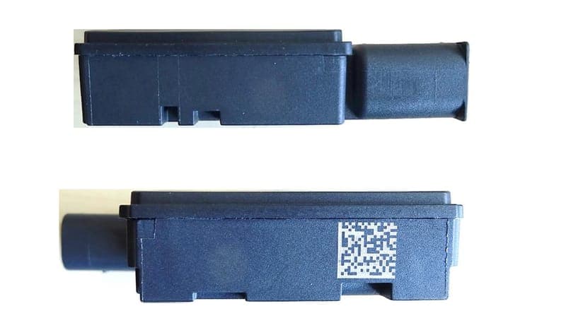
OAYSRR6A
Oct 03, 2023SRD for RTTT and other vehicle or fixed installation
Equipment Class
VRD - Part 95 Vehicular Radar Systems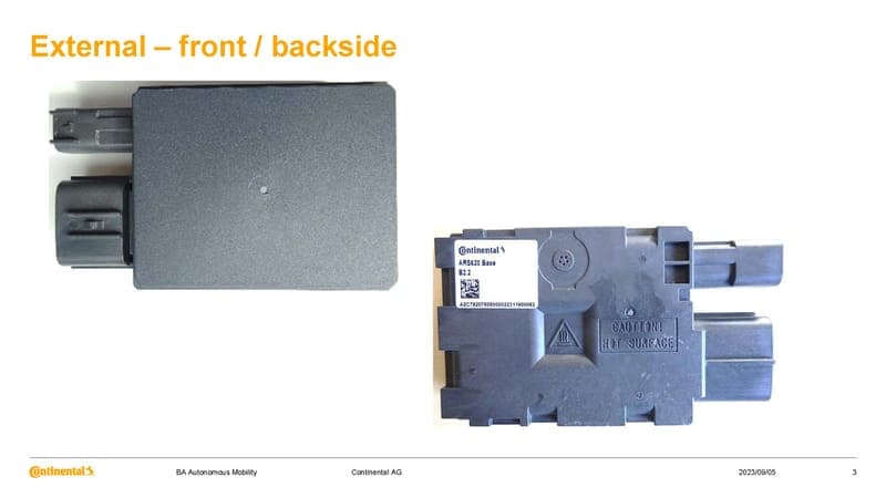
OAYARS6A
Sep 19, 2023SRD for RTTT and other vehicle or fixed installation
Equipment Class
VRD - Part 95 Vehicular Radar Systems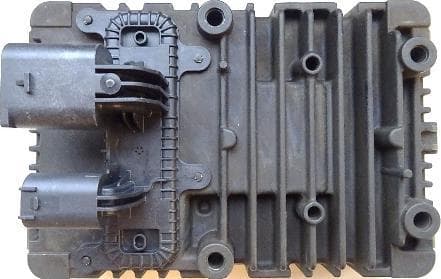
OAYARS5A
Dec 17, 2020SRD for RTTT and other vehicle or fixed installation
Equipment Class
VRD - Part 95 Vehicular Radar Systems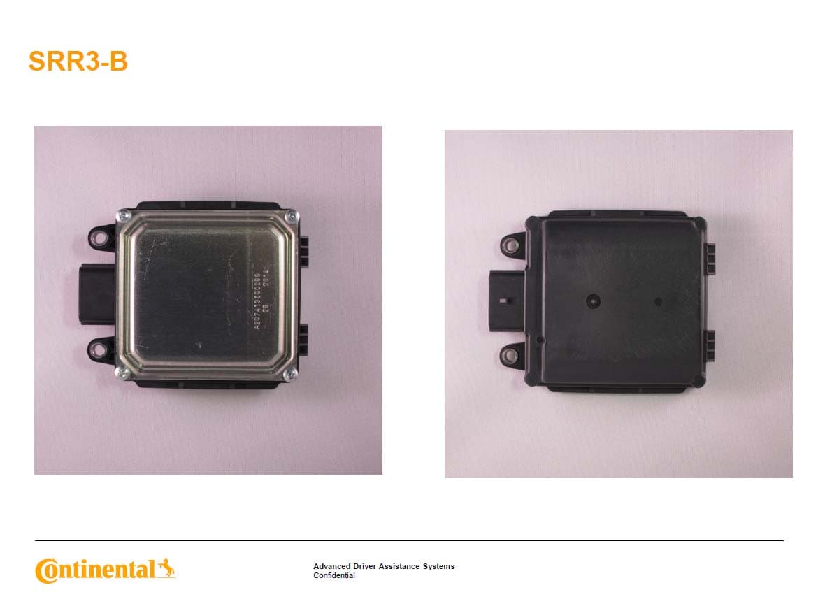
OAYSRR3B
Feb 11, 2015Advanced Driver Assistance Systems
Equipment Class
DXX - Part 15 Low Power Communication Device Transmitter