OCS-MT1000ANetwork Master Pro
Anritsu Corporation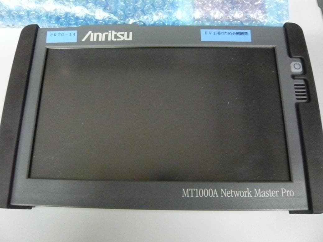
Click to zoom
Application Details
- Equipment Class
- DSS - Part 15 Spread Spectrum Transmitter
- Date of Grant
- Jun 24, 2014
- Application Purpose
- Original Equipment
- Date of Application
- Jun 24, 2014
- Equipment Note
- Network Master Pro
- Frequency Range
- 2402.00000000 - 2480.00000000
- Company
- Anritsu Corporation
- Country
- Japan
Documents & Files
Document Text
Text extracted from the exhibit documents filed with the FCC. Open a document above to read the original.
Users Manual
MT1000A Network Master Pro User’s Manual for WLAN/BT function First Edition ANRITSU CORPORATION Introduction Mainframe (MT1000A) The MT1000A Network Master Pro is a multipurpose telecommunications test instrument for field use. The installed options enable the Network Master to be used both as a full-featured transmission line quality tester and as an advanced signaling analyzer. Results are easily read from the large color LCD display, where the colors and graphical symbols facilitate interpretation. Together with the touch screen operation, this makes the Network Master very user-friendly in operation. The instrument has the following interface for data transfer and external communication: LAN interface (Wired/Wireless), Bluetooth interface and three USB ports. The instrument is powered by a rechargeable and replaceable intelligent high-capacity Li-Ion battery. The Network Master can also be powered via an external mains adapter for long-term measurements. 10 G Multirate Module (MU100010A) The MU100010A 10 G Multirate Module is a plug-in module of the Network Master Pro series. This module allows the Network Master to test a large variety of interfaces and systems up to 10Gbps, like OTN interfaces, Ethernet interfaces, SDH/SONET interfaces and PDH/DSn interfaces. The MU100010A can be configured to have two ports at all rates and interfaces. The instrument is thus ideal for both in-service and out- of-service transmission-quality measurement. Safety Overvoltage Category This equipment complies with overvoltage category II defined in IEC 61010. DO NOT connect this equipment to the power supply of overvoltage category III or IV. Repair Only qualified service personnel with a knowledge of electrical fire and shock hazards should service this equipment. This equipment cannot be repaired by the operator. DO NOT attempt to remove the equipment covers or unit covers or to disassemble internal components. In addition, there is a risk of damage to precision components. Battery When replacing the battery, use the specified battery and insert it with the correct polarity. If the wrong battery is used, or if the battery is inserted with reversed polarity, there is a risk of explosion causing severe injury or death. DO NOT expose batteries to heat or fire. Do not expose batteries to fire. This is dangerous and can result in explosions or fire. Heating batteries may cause them to leak or explode. LCD This equipment uses a Liquid Crystal Display (LCD). DO NOT subject the equipment to excessive force or drop it. If the LCD is subjected to strong mechanical shock, it may break and liquid may leak. This liquid is very caustic and poisonous.DO NOT touch it, ingest it, or get in your eyes. If it is ingested accidentally, spit it out immediately, rinse your mouth with water and seek medical help. If it enters your eyes accidentally, do not rub your eyes, rinse them with clean running water and seek medical help. If the liquid gets on your skin or clothes, wash it off carefully and thoroughly. External Storage This equipment uses a USB memory as external storage media for storing data and programs. If this media is mishandled or becomes faulty, important data may be lost. To prevent this chance occurrence, all important data and programs should be backed-up. Anritsu will not be held responsible for lost data. Use in Residential Environment This equipment is designed for an industrial environment. In a residential environment, this equipment may cause radio interference in which case the user may be required to take adequate measures. Use in Corrosive Atmospheres Exposure to corrosive gases such as hydrogen sulfide, sulfurous acid, and hydrogen chloride will cause faults and failures. Note that some organic solvents release corrosive gases. Configuration This chapter contains information about the basic configuration. Main Power Adapter The Network Master can be powered from the supplied AC mains adapter. Always use AC mains adapter delivered from Anritsu. Anritsu Part No. G0309A. To connect the mains power adapter to the Network Master, follow the procedure below: 1. Insert the mains adapter's DC power plug into the socket connector marked '18V DC'. The DC input connector is located on the right-hand side of Network Master's connector panel. 2. Connect the AC plug of the mains adapter to the mains and switch on the mains wall outlet. Rechargeable Battery The Network Master is delivered with a 10.8 V Intelligent Li-Ion rechargeable and replaceable battery. Use only original batteries delivered from Anritsu, to prevent the risk of instrument damage or personal injury. Battery should only be charged at room temperature. To install or replace the battery in the Network Master, follow the procedure below: 1. Place the instrument on its front on a plain surface and unscrew the battery compartment lock on the side of the instrument. 2. To release the battery compartment door - press down on the notch while dragging it outwards. 3. Pull out the battery from the compartment, using the strap fixed to it. 4. When installing the battery, note the direction of the battery terminals. With the instrument placed on its front - and the battery compartment in front of you - the terminals should be in the upper left corner. 5. Re-install the battery compartment door and tighten the lock screw. Cables Cables are connected to the input and output connectors located on the connector panel of the instrument. When connecting the Network Master to the line, it is recommended always to use shielded cables of good quality. Support Stand The Network Master is equipped with a support stand keeping the instrument at a convenient angle during the operation. To extract the stand: pull out the metal bar underneath the instrument - it automatically stays in the correct position. Carrying Strap The included carrying strap can easily be mounted for your convenience when transporting and/or using the Network Master. The carrying strap is equipp…
Text truncated - open the document above for the full version.
External Photos
MT1000A PCB Layout Connector
ID Label/Location Info
APPLICATION MARK REVISIONS DATE NAME APPROVE 1. Over view This document describes about the attachment location of MT1000A certification label. 2. Label location Attach the label on the EMC shield plate as follows. QTY ITEM PART No. DESCRIPTION MATERIAL FINISH NOTE CHECKED BY PDM DRAWN BY Y.OISHI 24/Apr./2014 SCALE DEP APPROVED BY PDM DESIGNED BY Y.OISHI 24/Apr./2014 : TITLE MT1000A Label Location DRAWING No. 1/1 44W122685 -00
ID Label/Location Info
ANRITSU CORPORATION 5-1-1. ONNA. ATSUGI-SHI KANAGAWA 243-8555, JAPAN WARNING The instrument does not contain user serviceable parts, Service must be carried out by authorized personnel. This device complies with part 15 of the FCC Rules. Operation is subject to the following two conditions: (1) This device may not cause harmful interference, and (2) this device must accept any interference received, including interference that may cause undesired operation. Model: MT1000A FCC ID: OCS-MT1000A IC: 1259A-MT1000A CMIIT ID: 2014DJ2249 IFETEL: RCPANMT14-0759 ANRITSU CORPORATION 5-1-1. ONNA. ATSUGI-SHI KANAGAWA 243-8555, JAPAN WARNING The instrument does not contain user serviceable parts, Service must be carried out by authorized personnel. This device complies with part 15 of the FCC Rules. Operation is subject to the following two conditions: (1) This device may not cause harmful interference, and (2) this device must accept any interference received, including interference that may cause undesired operation. Model: MT1000A FCC ID: OCS-MT1000A IC: 1259A-MT1000A CMIIT ID: 2014DJ2249 IFETEL: RCPANMT14-0759
Internal Photos
Controller board Controller board Photo Anritsu Corporation Network Master Pro [Model: MT1000A] RF Module (With Shield) RF Module (Without Shield)
RF Exposure Info
Test report No. : 10229872S-A Page : 2 of 47 Issued date : May 14, 2014 Revised date : June 19, 2014 FCC ID : OCS-MT1000A UL Japan, Inc. Shonan EMC Lab. 1-22-3 Megumigaoka, Hiratsuka-shi, Kanagawa-ken, 259-1220 JAPAN Telephone: +81 463 50 6400 / Facsimile: +81 463 50 6401 REVISION HISTORY Revision Test report No.Date Page revisedContents Original 10229872S-AMay 14, 2014- - 1 10229872S-AJune 19, 201411, 12, 14 Page 11: Correction of 7.1, Page 12: Correction of Appendix 1-1, Page 14: Add image. *. By issue of new revision report, the report of an old revision becomes invalid. CONTENTS PAGE REVISION HISTORY ................................................................................................................................................... 2 CONTENTS .................................................................................................................................................... 2 SECTION 1: Customer information .................................................................................... 3 SECTION 2: Equipment under test (EUT) ......................................................................... 3 2.1 Identification of EUT .......................................................................................................... 3 2.2 Product Description ............................................................................................................. 3 2.3 Tx output power specification (antenna port terminal conducted) ...................................... 4 2.4 Maximum output power which may possible ...................................................................... 4 SECTION 3: Test specification, procedures and results .................................................... 5 3.1 Test specification ................................................................................................................. 5 3.2 Exposure limit ..................................................................................................................... 5 3.3 Procedure and result ............................................................................................................ 5 3.4 Test location ........................................................................................................................ 6 3.5 Confirmation before SAR testing ........................................................................................ 6 3.6 Confirmation after SAR testing ........................................................................................... 7 3.7 Test setup of EUT and SAR measurement procedure ......................................................... 7 SECTION 4: Operation of EUT during testing .................................................................. 8 SECTION 5: Uncertainty assessment (SAR measurement) .............................................. 9 SECTION 6: Confirmation before testing........................................................................... 10 6.1 SAR reference power measurement (antenna terminal conducted average power of EUT) ................ 10 6.2 Comparison of power of EUT with the past tested ..................................................................... 10 SECTION 7: Measurement results ...................................................................................... 11 7.1 SAR test results ................................................................................................................... 11 Contents of appendixes APPENDIX 1: Photographs of test setup ............................................................................... 12 Appendix 1-1 Photograph of EUT and antenna position ............................................................................ 12 Appendix 1-2 EUT and support equipment ................................................................................................ 14 Appendix 1-3 Photograph of test setup ...................................................................................................... 14 APPENDIX 2: SAR Measurement data ................................................................................. 15 Appendix 2-1 Evaluation procedure ........................................................................................................... 15 Appendix 2-2 SAR measurement data ....................................................................................................... 16 APPENDIX 3: Test instruments ............................................................................................. 23 Appendix 3-1 Equipment used ................................................................................................................... 23 Appendix 3-2 Configuration and peripherals ............................................................................................. 24 Appendix 3-3 Test system specification ..................................................................................................... 25 Appendix 3-4 Simulated tissues composition and parameter confirmation ................................................ 26 Appendix 3-5 System check results............................................................................................................ 26 Appendix 3-6 System check measurement data ......................................................................................... 27 Appendix 3-7 System check uncertainty .................................................................................................... 28 Appendix 3-8 Calibration certificate: E-Field Probe (EX3DV4) ............................................................... 29 Appendix 3-9 Calibration certificate: Dipole (D2450V2) .......................................................................... 40 Test report No. : 10229872S-A Page : 3 of 47 Issued date : May 14, 2014 FCC ID : OCS-MT1000A UL Japan, Inc. Shonan EMC Lab. 1-22-3 Megumigaoka, Hiratsuka-shi, Kanagawa-…
Text truncated - open the document above for the full version.
RF Exposure Info
Test report No. : 10229872S-A Page : 15 of 47 Issued date : May 14, 2014 FCC ID : OCS-MT1000A UL Japan, Inc. Shonan EMC Lab. 1-22-3 Megumigaoka, Hiratsuka-shi, Kanagawa-ken, 259-1220 JAPAN Telephone: +81 463 50 6400 / Facsimile: +81 463 50 6401 APPENDIX 2: SAR Measurement data Appendix 2-1: Evaluation procedure The SAR evaluation was performed with the following procedure: Step 1: Measurement of the E-field at a fixed location above the central position of flat phantom was used as a reference value for assessing the power drop. Step 2: The SAR distribution at the exposed side of head or body position was measured at a distance of each device from the inner surface of the shell. The area covered the entire dimension of the antenna of EUT and suitable horizontal grid spacing of EUT. Based on these data, the area of the maximum absorption was determined by splines interpolation. Step 3: Around this point found in the Step 2 (area scan), a volume of 30mm(X axis)30mm(Y axis)30mm(Z axis) (or more) was assessed by measuring 777 points (or more) under 3GHz. And for any secondary peaks found in the Step2 which are within 2dB of the SAR limit (1.6W/kg), this Step3 (Zoom scan) is repeated. On the basis of this data set, the spatial peak SAR value was evaluated under the following procedure: (1) The data at the surface were extrapolated, since the center of the dipoles is 1mm away from the tip of the probe and the distance between the surface and the lowest measuring point is 2mm. The extrapolation was based on a least square algorithm. A polynomial of the fourth order was calculated through the points in z- axes. This polynomial was then used to evaluate the points between the surface and the probe tip. (2) The maximum interpolated value was searched with a straightforward algorithm. Around this maximum the SAR values averaged over the spatial volumes (1g or 10g) were computed by the 3D-Spline interpolation algorithm. The 3D-Spline is composed of three one-dimensional splines with the “Not a knot"-condition (in x, y and z-directions). The volume was integrated with the trapezoidal-algorithm. One thousand points (101010) were interpolated to calculate the average. (3) All neighboring volumes were evaluated until no neighboring volume with a higher average value was found. Step 4: Re-measurement of the E-field at the same location as in Step 1 for the assessment of the power drift. Step 5: Repeat Step 1-Step 4 with other condition or/and setup of EUT. Test report No. : 10229872S-A Page : 16 of 47 Issued date : May 14, 2014 FCC ID : OCS-MT1000A UL Japan, Inc. Shonan EMC Lab. 1-22-3 Megumigaoka, Hiratsuka-shi, Kanagawa-ken, 259-1220 JAPAN Telephone: +81 463 50 6400 / Facsimile: +81 463 50 6401 Appendix 2-2: SAR measurement data Step 1: Change the setup positions Plot 1-1: Top&touch (separation distance=0mm) / 11b(1Mbps), 2412MHz (1ch.) EUT: Network Master Pro; Type: MT1000A; Serial: 708336014 Communication System: Wi-fi_2.4GHz; Communication System Frame Length in ms: 0; Communication System PAR: 0; PMF: 1 Frequency: 2412 MHz; Crest Factor: 1.0 Medium: M2450; Medium parameters used: f = 2412 MHz; σ = 1.923 S/m; ε r = 52.147; ρ = 1000 kg/m 3 Measurement Standard: DASY5 (IEEE/IEC/ANSI C63.19-2007) DASY Configuration: -Probe: EX3DV4 - SN3679; ConvF(6.82, 6.82, 6.82); Calibrated: 2013/07/22; -Sensor-Surface: 2mm (Mechanical Surface Detection), z = 1.0, 31.0, 161.0 -Electronics: DAE4 Sn626; Calibrated: 2013/09/17 -Phantom: ELI v4.0; Type: QDOVA001BA; Serial: 1059; Phantom section: Flat Section -DASY52 52.8.2(969); SEMCAD X 14.6.6(6824) (14.0408)Top,11b,1Mbps,1ch,2412MHz,d0mm,pwr=12500/ Area Scan:96x264,stp12(mm) (9x23x1): Measurement grid: dx=12mm, dy=12mm, Maximum value of SAR (measured) = 0.817 W/kg Area Scan:96x264,stp12(mm) (81x221x1): Interpolated grid: dx=1.200 mm, dy=1.200 mm, Maximum value of SAR (interpolated) = 0.932 W/kg Z Scan;160,stp5(mm) (1x1x33): Measurement grid: dx=20mm, dy=20mm, dz=5mm, Maximum value of SAR (measured) = 0.909 W/kg Zoom Scan:30x30x30,stp5-5-5(mm) (7x7x7)/Cube 0: Measurement grid: dx=5mm, dy=5mm, dz=5mm Reference Value = 20.805 V/m; Power Drift = -0.12 dB, Maximum value of SAR (measured) = 0.898 W/kg, Peak SAR (extrapolated) = 1.269 mW/g SAR(1 g) = 0.540 mW/g; SAR(10 g) = 0.202 mW/g Remarks: *. Date tested: 2014/04/08; Tested by: Tomochika Sato; Tested place:No.7 shielded room, *.liquid depth: 153mm; Position: distance of EUT to phantom: 0mm (2mm to liquid); ambient: 22.5 1deg.C. / 40 10 %RH, *.liquid temperature: 21.7(start)/21.8(end)/21.6(in check) deg.C.; *.White cubic: zoom scan area, Red cubic: big=SAR(10g )/small=SAR(1g) Test report No. : 10229872S-A Page : 17 of 47 Issued date : May 14, 2014 FCC ID : OCS-MT1000A UL Japan, Inc. Shonan EMC Lab. 1-22-3 Megumigaoka, Hiratsuka-shi, Kanagawa-ken, 259-1220 JAPAN Telephone: +81 463 50 6400 / Facsimile: +81 463 50 6401 Appendix 2-2: SAR measurement data (cont'd) Step 1: Change the setup positions (cont'd) Plot 1-2: Front&touch (separation distance=0mm) / 11b(1Mbps), 2412MHz (1ch.) EUT: Network Master Pro; Type: MT1000A; Serial: 708336014 Communication System: Wi-fi_2.4GHz; Communication System Frame Length in ms: 0; Communication System PAR: 0; PMF: 1 Frequency: 2412 MHz; Crest Factor: 1.0 Medium: M2450; Medium parameters used: f = 2412 MHz; σ = 1.923 S/m; ε r = 52.147; ρ = 1000 kg/m 3 Measurement Standard: DASY5 (IEEE/IEC/ANSI C63.19-2007) DASY Configuration: -Probe: EX3DV4 - SN3679; ConvF(6.82, 6.82, 6.82); Calibrated: 2013/07/22; -Sensor-Surface: 2mm (Mechanical Surface Detection), z = 1.0, 31.0, 161.0 -Electronics: DAE4 Sn626; Calibrated: 2013/09/17 -Phantom: ELI v4.0; Type: QDOVA001BA; Serial: 1059; Phantom section: Flat Section -DASY52 52.8.2(969); SEMCAD X 14.6.6(6824) (14.0408)Front,11b,1Mbps,1ch,2412MHz,d0mm,pwr=12500/ Area Scan:180x264,stp12(mm) (16x23x1): Measurement grid: dx=12mm, dy=12mm, Maximum value of SAR (measured) = 0.119 W/kg Area Scan:180x264,stp12(mm) (151x221x1): Interpolated grid: dx=1.200 mm,…
Text truncated - open the document above for the full version.
RF Exposure Info
Test report No. : 10229872S-A Page : 29 of 47 Issued date : May 14, 2014 FCC ID : OCS-MT1000A UL Japan, Inc. Shonan EMC Lab. 1-22-3 Megumigaoka, Hiratsuka-shi, Kanagawa-ken, 259-1220 JAPAN Telephone: +81 463 50 6400 / Facsimile: +81 463 50 6401 Appendix 3-8: Calibration certificate: E-Field Probe (EX3DV4) Test report No. : 10229872S-A Page : 30 of 47 Issued date : May 14, 2014 FCC ID : OCS-MT1000A UL Japan, Inc. Shonan EMC Lab. 1-22-3 Megumigaoka, Hiratsuka-shi, Kanagawa-ken, 259-1220 JAPAN Telephone: +81 463 50 6400 / Facsimile: +81 463 50 6401 Appendix 3-8: Calibration certificate: E-Field Probe (EX3DV4) (cont’d) Test report No. : 10229872S-A Page : 31 of 47 Issued date : May 14, 2014 FCC ID : OCS-MT1000A UL Japan, Inc. Shonan EMC Lab. 1-22-3 Megumigaoka, Hiratsuka-shi, Kanagawa-ken, 259-1220 JAPAN Telephone: +81 463 50 6400 / Facsimile: +81 463 50 6401 Appendix 3-8: Calibration certificate: E-Field Probe (EX3DV4) (cont’d) Test report No. : 10229872S-A Page : 32 of 47 Issued date : May 14, 2014 FCC ID : OCS-MT1000A UL Japan, Inc. Shonan EMC Lab. 1-22-3 Megumigaoka, Hiratsuka-shi, Kanagawa-ken, 259-1220 JAPAN Telephone: +81 463 50 6400 / Facsimile: +81 463 50 6401 Appendix 3-8: Calibration certificate: E-Field Probe (EX3DV4) (cont’d) Test report No. : 10229872S-A Page : 33 of 47 Issued date : May 14, 2014 FCC ID : OCS-MT1000A UL Japan, Inc. Shonan EMC Lab. 1-22-3 Megumigaoka, Hiratsuka-shi, Kanagawa-ken, 259-1220 JAPAN Telephone: +81 463 50 6400 / Facsimile: +81 463 50 6401 Appendix 3-8: Calibration certificate: E-Field Probe (EX3DV4) (cont’d) Test report No. : 10229872S-A Page : 34 of 47 Issued date : May 14, 2014 FCC ID : OCS-MT1000A UL Japan, Inc. Shonan EMC Lab. 1-22-3 Megumigaoka, Hiratsuka-shi, Kanagawa-ken, 259-1220 JAPAN Telephone: +81 463 50 6400 / Facsimile: +81 463 50 6401 Appendix 3-8: Calibration certificate: E-Field Probe (EX3DV4) (cont’d) Test report No. : 10229872S-A Page : 35 of 47 Issued date : May 14, 2014 FCC ID : OCS-MT1000A UL Japan, Inc. Shonan EMC Lab. 1-22-3 Megumigaoka, Hiratsuka-shi, Kanagawa-ken, 259-1220 JAPAN Telephone: +81 463 50 6400 / Facsimile: +81 463 50 6401 Appendix 3-8: Calibration certificate: E-Field Probe (EX3DV4) (cont’d) Test report No. : 10229872S-A Page : 36 of 47 Issued date : May 14, 2014 FCC ID : OCS-MT1000A UL Japan, Inc. Shonan EMC Lab. 1-22-3 Megumigaoka, Hiratsuka-shi, Kanagawa-ken, 259-1220 JAPAN Telephone: +81 463 50 6400 / Facsimile: +81 463 50 6401 Appendix 3-8: Calibration certificate: E-Field Probe (EX3DV4) (cont’d) Test report No. : 10229872S-A Page : 37 of 47 Issued date : May 14, 2014 FCC ID : OCS-MT1000A UL Japan, Inc. Shonan EMC Lab. 1-22-3 Megumigaoka, Hiratsuka-shi, Kanagawa-ken, 259-1220 JAPAN Telephone: +81 463 50 6400 / Facsimile: +81 463 50 6401 Appendix 3-8: Calibration certificate: E-Field Probe (EX3DV4) (cont’d) Test report No. : 10229872S-A Page : 38 of 47 Issued date : May 14, 2014 FCC ID : OCS-MT1000A UL Japan, Inc. Shonan EMC Lab. 1-22-3 Megumigaoka, Hiratsuka-shi, Kanagawa-ken, 259-1220 JAPAN Telephone: +81 463 50 6400 / Facsimile: +81 463 50 6401 Appendix 3-8: Calibration certificate: E-Field Probe (EX3DV4) (cont’d) Test report No. : 10229872S-A Page : 39 of 47 Issued date : May 14, 2014 FCC ID : OCS-MT1000A UL Japan, Inc. Shonan EMC Lab. 1-22-3 Megumigaoka, Hiratsuka-shi, Kanagawa-ken, 259-1220 JAPAN Telephone: +81 463 50 6400 / Facsimile: +81 463 50 6401 Appendix 3-8: Calibration certificate: E-Field Probe (EX3DV4) (cont’d) Test report No. : 10229872S-A Page : 40 of 47 Issued date : May 14, 2014 FCC ID : OCS-MT1000A UL Japan, Inc. Shonan EMC Lab. 1-22-3 Megumigaoka, Hiratsuka-shi, Kanagawa-ken, 259-1220 JAPAN Telephone: +81 463 50 6400 / Facsimile: +81 463 50 6401 Appendix 3-9: Calibration certificate: Dipole (D2450V2) Test report No. : 10229872S-A Page : 41 of 47 Issued date : May 14, 2014 FCC ID : OCS-MT1000A UL Japan, Inc. Shonan EMC Lab. 1-22-3 Megumigaoka, Hiratsuka-shi, Kanagawa-ken, 259-1220 JAPAN Telephone: +81 463 50 6400 / Facsimile: +81 463 50 6401 Appendix 3-9: Calibration certificate: Dipole (D2450V2) (cont’d) Test report No. : 10229872S-A Page : 42 of 47 Issued date : May 14, 2014 FCC ID : OCS-MT1000A UL Japan, Inc. Shonan EMC Lab. 1-22-3 Megumigaoka, Hiratsuka-shi, Kanagawa-ken, 259-1220 JAPAN Telephone: +81 463 50 6400 / Facsimile: +81 463 50 6401 Appendix 3-9: Calibration certificate: Dipole (D2450V2) (cont’d) Test report No. : 10229872S-A Page : 43 of 47 Issued date : May 14, 2014 FCC ID : OCS-MT1000A UL Japan, Inc. Shonan EMC Lab. 1-22-3 Megumigaoka, Hiratsuka-shi, Kanagawa-ken, 259-1220 JAPAN Telephone: +81 463 50 6400 / Facsimile: +81 463 50 6401 Appendix 3-9: Calibration certificate: Dipole (D2450V2) (cont’d) Test report No. : 10229872S-A Page : 44 of 47 Issued date : May 14, 2014 FCC ID : OCS-MT1000A UL Japan, Inc. Shonan EMC Lab. 1-22-3 Megumigaoka, Hiratsuka-shi, Kanagawa-ken, 259-1220 JAPAN Telephone: +81 463 50 6400 / Facsimile: +81 463 50 6401 Appendix 3-9: Calibration certificate: Dipole (D2450V2) (cont’d) Test report No. : 10229872S-A Page : 45 of 47 Issued date : May 14, 2014 FCC ID : OCS-MT1000A UL Japan, Inc. Shonan EMC Lab. 1-22-3 Megumigaoka, Hiratsuka-shi, Kanagawa-ken, 259-1220 JAPAN Telephone: +81 463 50 6400 / Facsimile: +81 463 50 6401 Appendix 3-9: Calibration certificate: Dipole (D2450V2) (cont’d) Test report No. : 10229872S-A Page : 46 of 47 Issued date : May 14, 2014 FCC ID : OCS-MT1000A UL Japan, Inc. Shonan EMC Lab. 1-22-3 Megumigaoka, Hiratsuka-shi, Kanagawa-ken, 259-1220 JAPAN Telephone: +81 463 50 6400 / Facsimile: +81 463 50 6401 Appendix 3-9: Calibration certificate: Dipole (D2450V2) (cont’d) Test report No. : 10229872S-A Page : 47 of 47 Issued date : May 14, 2014 FCC ID : OCS-MT1000A UL Japan, Inc. Shonan EMC Lab. 1-22-3 Megumigaoka, Hiratsuka-shi, Kanagawa-ken, 259-1220 JAPAN Telephone: +81 463 50 6400 / Facsimile: +81 463 50 6401 Appendix 3-9: Calibration certificate: Dipole (D2450V2) (cont’d) (End of Report)
Test Report
Test report No. : 10229869S-A Page : 2 of 57 Issued date : April 25, 2014 Revised date : June 19, 2014 FCC ID : OCS-MT1000A UL Japan, Inc. Shonan EMC Lab. 1-22-3 Megumigaoka, Hiratsuka-shi, Kanagawa-ken, 259-1220 JAPAN Telephone: +81 463 50 6400 Facsimile: +81 463 50 6401 REVISION HISTORY Original Test Report No.: 10229869S-A Revision Test report No. Date Page revised Contents - (Original) 10229869S-A April 25, 2014 - - 1 10229869S-A June 19, 2014 4, 6, 19, 49-51 P4: Correction of 2.2 P6: Correction of 3.2 P19: Replacement of data P49-51: Correction of typo on data Test report No. : 10229869S-A Page : 3 of 57 Issued date : April 25, 2014 FCC ID : OCS-MT1000A UL Japan, Inc. Shonan EMC Lab. 1-22-3 Megumigaoka, Hiratsuka-shi, Kanagawa-ken, 259-1220 JAPAN Telephone: +81 463 50 6400 Facsimile: +81 463 50 6401 Contents Page SECTION 1: Customer information .................................................................................... 4 SECTION 2: Equipment under test (E.U.T.) ...................................................................... 4 SECTION 3: Test specification, procedures & results ........................................................ 6 SECTION 4: Operation of E.U.T. during testing ................................................................ 9 SECTION 5: Conducted emission ...................................................................................... 11 SECTION 6: Carrier frequency separation ....................................................................... 12 SECTION 7: 20dB bandwidth & Occupied bandwidth (99%) ........................................ 12 SECTION 8: Number of hopping frequency ..................................................................... 12 SECTION 9: Dwell time ..................................................................................................... 12 SECTION 10: Maximum peak output power .................................................................... 12 SECTION 11: Spurious emissions (Antenna port conducted) .......................................... 12 SECTION 12: Radiated emission ....................................................................................... 13 Contents of APPENDIXES ................................................................................................... 15 APPENDIX 1: Data of radio tests..................................................................................... 16 APPENDIX 2: Test instruments ....................................................................................... 54 APPENDIX 3: Photographs of test setup ......................................................................... 55 Test report No. : 10229869S-A Page : 4 of 57 Issued date : April 25, 2014 Revised date : June 19, 2014 FCC ID : OCS-MT1000A UL Japan, Inc. Shonan EMC Lab. 1-22-3 Megumigaoka, Hiratsuka-shi, Kanagawa-ken, 259-1220 JAPAN Telephone: +81 463 50 6400 Facsimile: +81 463 50 6401 SECTION 1: Customer information Company Name : Anritsu Corporation Address : 5-1-1 Onna, Atsugi-shi, Kanagawa, 243-8555 Japan Telephone Number : +81-46-296-6669 Facsimile Number : +81-46-225-8380 Contact Person : Yasuyuki Oishi SECTION 2: Equipment under test (E.U.T.) 2.1 Identification of E.U.T. Type of Equipment : Network Master Pro Model Number : MT1000A Serial Number : 708230036 Rating : Mains adapter: Input: AC 100 - 240V 50/60Hz, Output: DC18V 3.62A Battery: DC 10.8V Country of Mass-production : Denmark Condition of EUT : Production prototype (Not for Sale: This sample is equivalent to mass-produced items.) Receipt Date of Sample : February 24, 2014 Modification of EUT : No modification by the test lab. 2.2 Product description Model: MT1000A (referred to as the EUT in this report) is Network Master Pro. Clock frequency(ies) in the system : 20 MHz, 200 MHz, 625 MHz <Bluetooth part> Equipment type : Transceiver Frequency of operation : 2402-2480MHz Bandwidth & channel spacing : 79MHz & 1MHz Type of modulation : GFSK, π/4DQPSK, 8DPSK Antenna type : Dipole Antenna gain : 3.0dBi Antenna connector type : IPEX MHF Connector (U.FL compatible) Operation temperature range : 0 to +50 deg.C. <Wireless LAN part> Equipment type : Transceiver Frequency of operation : 2412-2462MHz Bandwidth & channel spacing : 20MHz & 5MHz Type of modulation : CCK,OFDM Antenna type : D…
Text truncated - open the document above for the full version.
Contact Information
Applicant
Yasuyuki Oishi(R&D Engineer)
Technical Contact
UL Japan, Inc.Toyokazu Imamura
[email protected]81-463-50-6400
1-22-3 Megumigaoka, Hiratsuka-shi · Kanagawa-ken · Japan
Test Firm
UL Japan, Inc. Shonan EMC EMC Lab.Tetsuya Hashimoto
Technical Specifications
| # | Rule Parts | Frequency Range | Power Output |
|---|---|---|---|
| 1 | 15C | 2.40 GHz - 2.48 GHz | 7.80 mW |
Other Applications from Anritsu Corporation
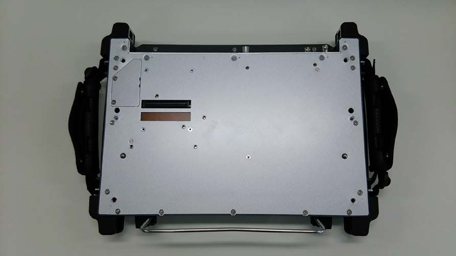
OCS-MT1100A
Oct 08, 2014Network Master Flex
Equipment Class
DSS - Part 15 Spread Spectrum Transmitter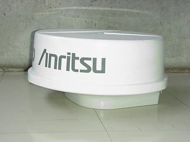
OCS6DXRA775UA
Feb 22, 2000Marine Radar RA775UA
Equipment Class
MRD - Marine Radar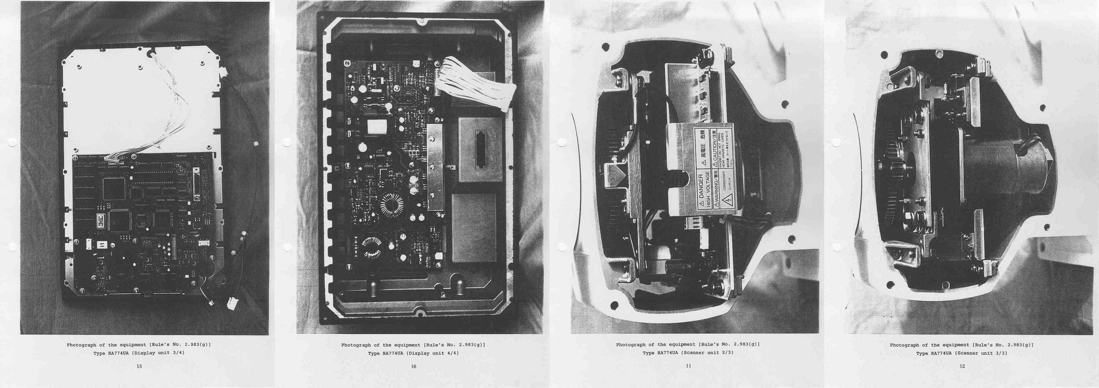
OCS6DXRA774UA
Apr 28, 1999Marine Radar RA774UA
Equipment Class
MRD - Marine Radar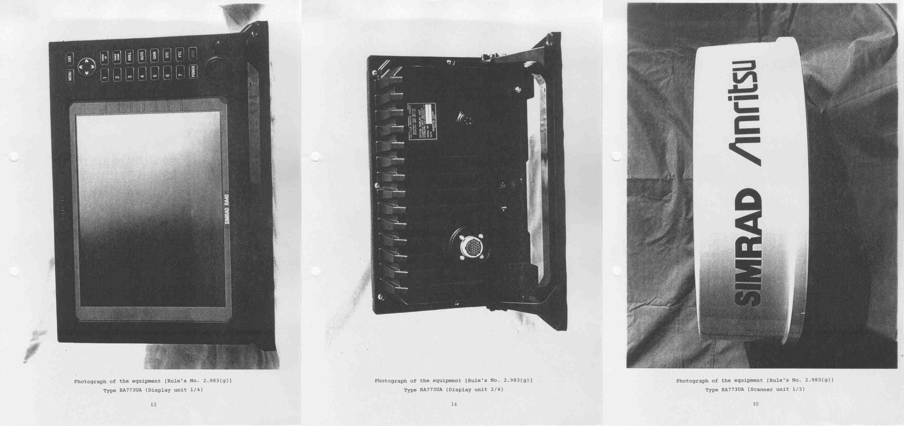
OCS6DXRA773UA
Mar 30, 1999Marine Radar RA773UA
Equipment Class
MRD - Marine Radar