OCS-MT1100ANetwork Master Flex
Anritsu Corporation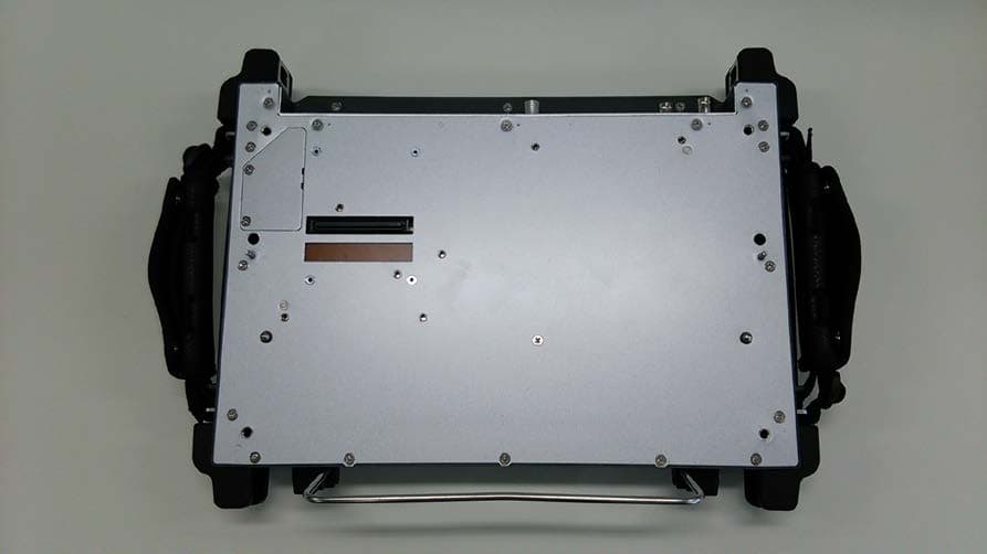
Click to zoom
Application Details
- Equipment Class
- DSS - Part 15 Spread Spectrum Transmitter
- Date of Grant
- Oct 08, 2014
- Application Purpose
- Original Equipment
- Date of Application
- Oct 08, 2014
- Equipment Note
- Network Master Flex
- Frequency Range
- 2402.00000000 - 2480.00000000
- Company
- Anritsu Corporation
- Country
- Japan
Documents & Files
Document Text
Text extracted from the exhibit documents filed with the FCC. Open a document above to read the original.
Users Manual
MT1100A Network Master Flex User’s Manual for WLAN/BT function First Edition ANRITSU CORPORATION Introduction Mainframe (MT1100A) The MT1100A Network Master Flex is a multipurpose telecommunications test instrument up to 100 Gbit/s for field use. The installed options enable the Network Master to be used both as a full-featured transmission line quality tester and as an advanced signaling analyzer. Results are easily read from the large color LCD display, where the colors and graphical symbols facilitate interpretation. Together with the touch screen operation, this makes the Network Master very user-friendly in operation. The instrument has the following interface for data transfer and external communication: LAN interface (Wired/Wireless), Bluetooth® interface and three USB ports. The instrument is powered by the MU110001A/MU110002A power supply module unit. Power Button Inlet Touch Screen Battery Safety Overvoltage Category This equipment complies with overvoltage category II defined in IEC 61010. DO NOT connect this equipment to the power supply of overvoltage category III or IV. Repair Only qualified service personnel with a knowledge of electrical fire and shock hazards should service this equipment. This equipment cannot be repaired by the operator. DO NOT attempt to remove the equipment covers or unit covers or to disassemble internal components. In addition, there is a risk of damage to precision components. Battery When replacing the battery, use the specified battery and insert it with the correct polarity. If the wrong battery is used, or if the battery is inserted with reversed polarity, there is a risk of explosion causing severe injury or death. DO NOT expose batteries to heat or fire. Do not expose batteries to fire. This is dangerous and can result in explosions or fire. Heating batteries may cause them to leak or explode. LCD This equipment uses a Liquid Crystal Display (LCD). DO NOT subject the equipment to excessive force or drop it. If the LCD is subjected to strong mechanical shock, it may break and liquid may leak. This liquid is very caustic and poisonous.DO NOT touch it, ingest it, or get in your eyes. If it is ingested accidentally, spit it out immediately, rinse your mouth with water and seek medical help. If it enters your eyes accidentally, do not rub your eyes, rinse them with clean running water and seek medical help. If the liquid gets on your skin or clothes, wash it off carefully and thoroughly. External Storage This equipment uses a USB memory as external storage media for storing data and programs. If this media is mishandled or becomes faulty, important data may be lost. To prevent this chance occurrence, all important data and programs should be backed-up. Anritsu will not be held responsible for lost data. Use in Residential Environment This equipment is designed for an industrial environment. In a residential environment, this equipment may cause radio interference in which case the user may be required to take adequate measures. This equipment is also used more than 20cm away from the human body. Use in Corrosive Atmospheres Exposure to corrosive gases such as hydrogen sulfide, sulfurous acid, and hydrogen chloride will cause faults and failures. Note that some organic solvents release corrosive gases. Configuration This chapter contains information about the basic configuration. Rechargeable Battery The Network Master is delivered with a 14.4 V Intelligent Li-Ion rechargeable and replaceable battery. Use only original batteries delivered from Anritsu, to prevent the risk of instrument damage or personal injury. Battery should only be charged at room temperature. To install or replace the battery in the Network Master, follow the procedure below: 1. Disconnect the power cable if it is connected. 2. Switch the Network Master OFF. 3. Place the instrument on its back on a plain surface and loosen the lock screw of the battery compartment. 4. Remove the lid of the battery compartment. 5. Pull out the battery from the compartment. 6. When installing the battery, note the direction of the battery terminals. With the instrument placed on its back - and the battery compartment in front of you - the terminals should be in the upper left corner. 7. Re-install the battery compartment door and tighten the lock screw. Cables Cables are connected to the input and output connectors located on the connector panel of the instrument. When connecting the Network Master to the line, it is recommended always to use shielded cables of good quality. Support Stand The Network Master is equipped with a support stand keeping the instrument at a convenient angle during the operation. To extract the stand: pull out the metal bar on rear of the instrument - it automatically stays in the correct position. Carrying Strap and Handle The included carrying strap can easily be mounted for your convenience when transporting and/or using the Network Master. The carrying strap is equipped with hooks for easy installation. Use the Carrying Strap around your sholder. Do not wrap the strap around your neck. Man-Machine-Interface Touch Screen Display The 12.1 inch active TFT display with SVGA resolution (800x600 pixels) is used for setups and for presentation of results. As the display includes touch screen functionality, it is possible to navigate and operate directly from it. Power Button The only physical operator key is the Power button. The Power button on the front panel of the instrument is used to switch power ON and OFF. In addition, the menu used for power-off also contains a few extra options (e.g. to lock the screen). Switching power ON When you press the Power button to switch on power, the TFT display presents you with a startup screen where you can select the application you want to use. Switching power OFF When you press the Power button to switch off power, a pop-up menu is displayed, containing the menu item Shut Down. Select the Shut Down menu item and then confirm by s…
Text truncated - open the document above for the full version.
External Photos
External Photo Anritsu Corporation [Model: MT1100A] Front Back External Photo Anritsu Corporation [Model: MT1100A] Side (Right) Side (Left) External Photo Anritsu Corporation [Model: MT1100A] Top Bottom
ID Label/Location Info
APPLICATION MARK REVISIONS DATE NAME APPROVE 1. Over view This document describes about the attachment location of MT1100A certification label. 2. Label location Attach the label on the rear panel as follows. QTY ITEM PART No. DESCRIPTION MATERIAL FINISH NOTE CHECKED BY PDM DRAWN BY Y.OISHI 12/Sep./2014 SCALE DEP APPROVED BY PDM DESIGNED BY Y.OISHI 12/Sep./2014 : TITLE MT1100A Label Location DRAWING No. 1/1 44W122942 -00
Internal Photos
Internal Photo Anritsu Corporation [Model: MT1100A ] Controller board Front Internal Photo Anritsu Corporation [Model: MT1100A ] Controller board Back Internal Photo Anritsu Corporation [Model: MT1100A ] Location Internal Photo Anritsu Corporation [Model: MT1100A ] Location Antenna Internal Photo Anritsu Corporation [Model: MT1100A ] Antenna Location Antenna Internal Photo Anritsu Corporation [Model: MT1100A ] RF Module with Shield Front Internal Photo Anritsu Corporation [Model: MT1100A ] RF Module with Shield Back Internal Photo Anritsu Corporation [Model: MT1100A ] RF Module without Shield
RF Exposure Info
UL Japan, Inc. Shonan EMC Lab. 1-22-3 Megumigaoka, Hiratsuka-shi, Kanagawa-ken, 259-1220 JAPAN Telephone : +81 463 50 6400 Facsimile : +81 463 50 6401 Applicant: Anritsu Corporation T ype of Equipm ent : N etw ork M aster Flex M odel No. : M T1100A FCC ID: OCS-M T1100A A nritsu C orporation declares that M odel : M T 11 00A complies with FCC radiation exposure requirement specified in the FCC Rules 2.1091. RF Exposure Calculations: T h e followin g in form ation provides th e m in im um separation distan ce for th e h igh est gain antenna provided with the “MT1100A“ as calculated from FCC Part 1, §1.1310, TABLE 1 (B) Limits for General Population / Uncontrolled Exposure. This calculation is based on the highest EIRP possible from the system , considering m aximum power and antenna gain, and considering a 1.0m W/cm ^2 uncontrolled exposure limit. The Friis form ula used was: S = (P * G) / (4* π * r 2 ) Where P = 10.00 mW (M aximum average output pow er w ith tolerance) *1) G = 2.00 N umerical A ntenna gain; equal to3.00dBi r =20.0 cm For: M T1100AS =0.00397 mW/cm 2 *1) The value is based on the specification provided by the custom er. No. : 10402743S-E-R1 RF Exposure / SAR Statement
Test Report
Test report No. : 10402743S-E-R1 Page : 2 of 61 Issued date : October 8, 2014 FCC ID : OCS-MT1100A UL Japan, Inc. Shonan EMC Lab. 1-22-3 Megumigaoka, Hiratsuka-shi, Kanagawa-ken, 259-1220 JAPAN Telephone: +81 463 50 6400 Facsimile: +81 463 50 6401 REVISION HISTORY Original Test Report No.: 10402743S-E Revision Test report No. Date Page revised Contents - (Original) 10402743S-E September 16, 2014 - - 1 10402743S-E-R1 October 8, 2014 - (Full revision) - Correction of 4.2 - Addition of data of average output power Test report No. : 10402743S-E-R1 Page : 3 of 61 Issued date : October 8, 2014 FCC ID : OCS-MT1100A UL Japan, Inc. Shonan EMC Lab. 1-22-3 Megumigaoka, Hiratsuka-shi, Kanagawa-ken, 259-1220 JAPAN Telephone: +81 463 50 6400 Facsimile: +81 463 50 6401 Contents Page SECTION 1: Customer information .................................................................................... 4 SECTION 2: Equipment under test (E.U.T.) ...................................................................... 4 SECTION 3: Test specification, procedures & results ........................................................ 6 SECTION 4: Operation of E.U.T. during testing ................................................................ 9 SECTION 5: Conducted emission ...................................................................................... 12 SECTION 6: Carrier frequency separation ....................................................................... 13 SECTION 7: 20dB bandwidth & Occupied bandwidth (99%) ........................................ 13 SECTION 8: Number of hopping frequency ..................................................................... 13 SECTION 9: Dwell time ..................................................................................................... 13 SECTION 10: Maximum peak output power .................................................................... 13 SECTION 11: Spurious emissions (Antenna port conducted) .......................................... 13 SECTION 12: Radiated emission ....................................................................................... 14 Contents of APPENDIXES ................................................................................................... 16 APPENDIX 1: Data of radio tests...................................................................................... 17 APPENDIX 2: Test instruments ........................................................................................ 56 APPENDIX 3: Photographs of test setup .......................................................................... 58 Test report No. : 10402743S-E-R1 Page : 4 of 61 Issued date : October 8, 2014 FCC ID : OCS-MT1100A UL Japan, Inc. Shonan EMC Lab. 1-22-3 Megumigaoka, Hiratsuka-shi, Kanagawa-ken, 259-1220 JAPAN Telephone: +81 463 50 6400 Facsimile: +81 463 50 6401 SECTION 1: Customer information Company Name : Anritsu Corporation Address : 5-1-1 Onna, Atsugi-shi, Kanagawa, 243-8555 Japan Telephone Number : +81-46-296-6669 Facsimile Number : +81-46-225-8380 Contact Person : Yasuyuki Oishi SECTION 2: Equipment under test (E.U.T.) 2.1 Identification of E.U.T. Type of Equipment : Network Master Flex Model Number : MT1100A Serial Number : Proto-17 Rating : AC 100 - 240V, 50/60Hz DC 16V/14.4V (Battery) Country of Mass-production : Japan Condition of EUT : Production prototype (Not for Sale: This sample is equivalent to mass-produced items.) Receipt Date of Sample : July 30, 2014 Modification of EUT : No modification by the test lab. 2.2 Product description Model: MT1100A (referred to as the EUT in this report) is Network Master Flex. Clock frequency(ies) in the system : 20 MHz, 200 MHz, 625 MHz <Bluetooth part> Equipment type : Transceiver Frequency of operation : 2402-2480MHz Bandwidth & channel spacing : 79MHz & 1MHz Type of modulation : GFSK, π/4DQPSK, 8DPSK Antenna type : Dipole Antenna gain : 3.0dBi Antenna connector type : IPEX MHF Connector (U.FL compatible) Operation temperature range : 0 to +40 deg.C. <Wireless LAN part> Equipment type : Transceiver Frequency of operation : 2412-2462MHz Bandwidth & channel spacing : 20MHz & 5MHz Type of modulation : CCK,OFDM Antenna type : Dipole Antenna gain : 3.0dBi Antenna connector type : IPEX MHF Connector (U.FL compatible) Operation temperature range : 0 to +40 deg.C * For Wireless LAN part, refer to the test report: 10402743S-D-R1. Test report No. : 10402743S-E-R1 Page : 5 of 61 Issued date : October 8, 2014 FCC ID : OCS-MT1100A UL Japan, Inc. Shonan EMC Lab. 1-22-3 Megumigaoka, Hiratsuka-shi, Kanagawa-ken, 259-1220 JAPAN Telephone: +81 463 50 6400 Facsimile: +81 463 50 6401 FCC 15.31 (e) The stable voltage (DC3.3V and DC1.8V) is provided constantly to RF part via regulator. Therefore, the EUT complies with the requirement. FCC 15.203 It is impossible for end users to replace the antenna, because the antenna is mounted inside of the EUT. Therefore the EUT complies with the requirement. Test report No. : 10402743S-E-R1 Page : 6 of 61 Issued date : October 8, 2014 FCC ID : OCS-MT1100A UL Japan, Inc. Shonan EMC Lab. 1-22-3 Megumigaoka, Hiratsuka-shi, Kanagawa-ken, 259-1220 JAPAN Telephone: +81 463 50 6400 Facsimile: +81 463 50 6401 SECTION 3: Test specification, procedures & results 3.1 Test specification Test specification : FCC Part 15 Subpart C: 2014, final revised on May 1, 2014 and effective June 2, 2014 Title : FCC 47CFR Part15 Radio Frequency Device Subpart C Intentional Radiators Section 15.207 Conducted limits Section 15.209 Radiated emission limits, general requirements Section 15.247 Operation within the bands 902-928MHz, 2400-2483.5MHz, and 5725-5850MHz 3.2 Procedures & Results Item Test Procedure SpecificationRemarks Deviation Worst Margin Results Conducted emission ANSI C63.4:2009 7. AC powerline conducted emission measurements FCC 15.207 - N/A 1.5dB Freq.: 0.20395MHz Detection: Average Phase: N Mode: Tx 2402MHz, DH5 Complied Carrier frequency separation FCC Public Notice DA 00…
Text truncated - open the document above for the full version.
Test Setup Photos
Test report No. : 10005707S-A Page : 21 of 23 UL Japan, Inc. Shonan EMC Lab. 1-22-3 Megumigaoka, Hiratsuka-shi, Kanagawa-ken, 259-1220 JAPAN Telephone : +81 463 50 6400 Facsimile : +81 463 50 6401 APPENDIX 3: Photographs of test setup Conducted emission Front Side Test Report No. : 10402743S-E-R1 58 of 61 Test report No. : 10005707S-A Page : 22 of 23 UL Japan, Inc. Shonan EMC Lab. 1-22-3 Megumigaoka, Hiratsuka-shi, Kanagawa-ken, 259-1220 JAPAN Telephone : +81 463 50 6400 Facsimile : +81 463 50 6401 Radiated emission Front Rear (below 1GHz) Rear (above 1GHz) Test Report No. : 10402743S-E-R1 59 of 61 Test report No. : 10005707S-A Page : 23 of 23 UL Japan, Inc. Shonan EMC Lab. 1-22-3 Megumigaoka, Hiratsuka-shi, Kanagawa-ken, 259-1220 JAPAN Telephone : +81 463 50 6400 Facsimile : +81 463 50 6401 Pre-check of the worst position (1/2) Position: a Position: b (using tilt stand) Test Report No. : 10402743S-E-R1 60 of 61 Test report No. : 10005707S-A Page : 24 of 23 UL Japan, Inc. Shonan EMC Lab. 1-22-3 Megumigaoka, Hiratsuka-shi, Kanagawa-ken, 259-1220 JAPAN Telephone : +81 463 50 6400 Facsimile : +81 463 50 6401 Pre-check of the worst position (2/2) Position: c Position: d (using tilt stand) END OF REPORT Test Report No. : 10402743S-E-R1 61 of 61
Contact Information
Applicant
Yasuyuki Oishi(R&D Engineer)
Technical Contact
UL Japan, Inc.Toyokazu Imamura
[email protected]81-463-50-6400
1-22-3 Megumigaoka, Hiratsuka-shi · Kanagawa-ken · Japan
Test Firm
UL Japan, Inc. Shonan EMC EMC Lab.Tetsuya Hashimoto
Technical Specifications
| # | Rule Parts | Frequency Range | Power Output |
|---|---|---|---|
| 1 | 15C | 2.40 GHz - 2.48 GHz | 9.00 mW |
Other Applications from Anritsu Corporation
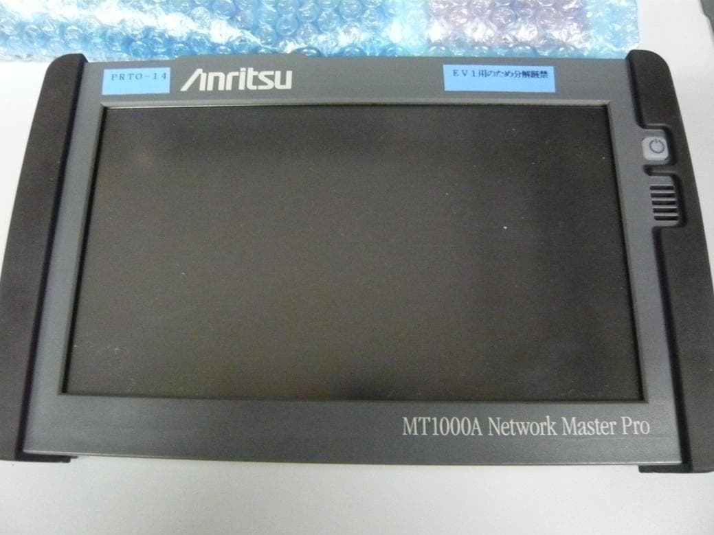
OCS-MT1000A
Jun 24, 2014Network Master Pro
Equipment Class
DSS - Part 15 Spread Spectrum Transmitter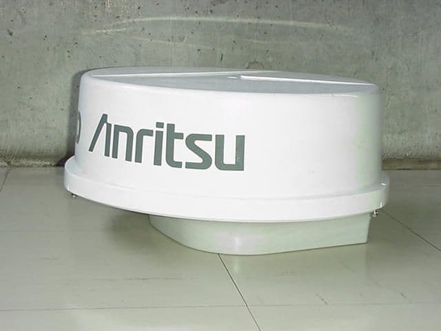
OCS6DXRA775UA
Feb 22, 2000Marine Radar RA775UA
Equipment Class
MRD - Marine Radar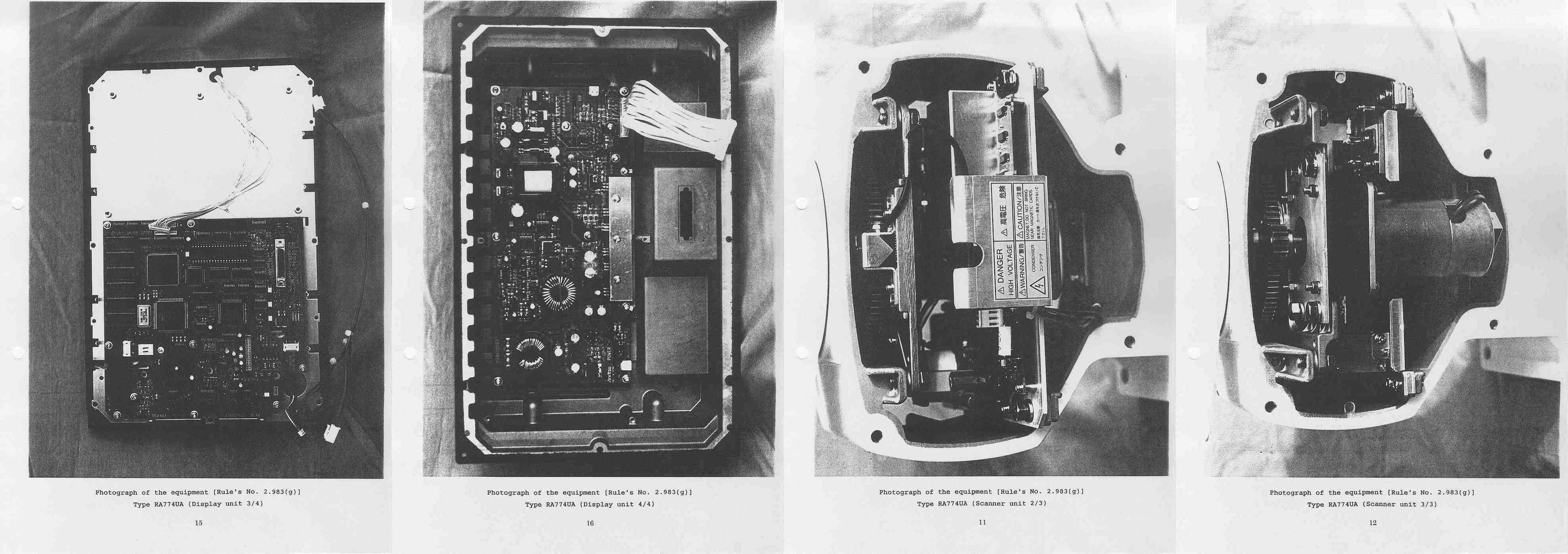
OCS6DXRA774UA
Apr 28, 1999Marine Radar RA774UA
Equipment Class
MRD - Marine Radar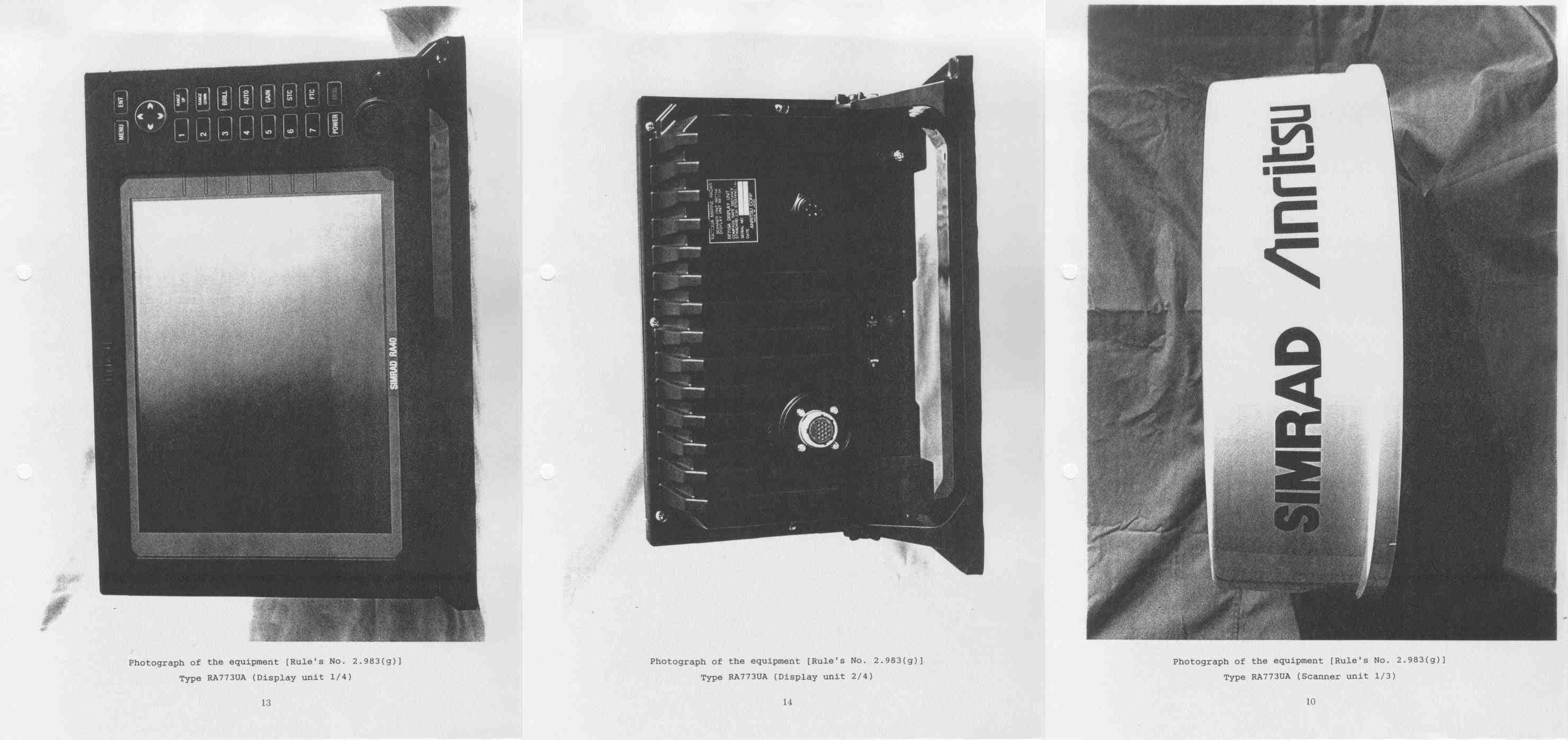
OCS6DXRA773UA
Mar 30, 1999Marine Radar RA773UA
Equipment Class
MRD - Marine Radar