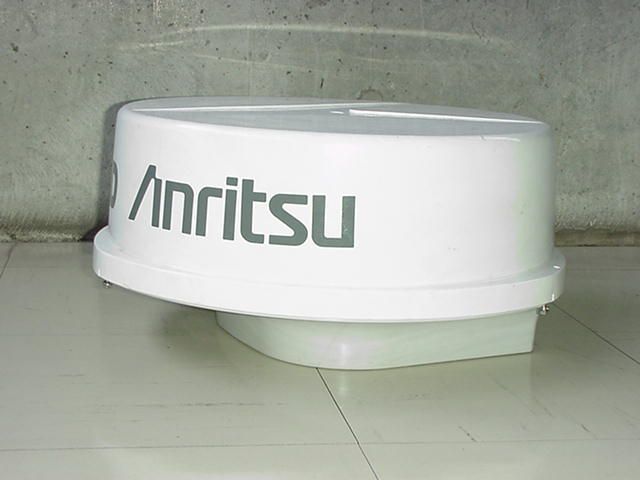
OCS6DXRA775UAMarine Radar RA775UA
Anritsu Corporation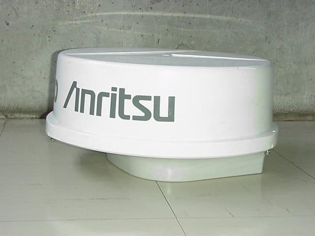
Click to zoom
Application Details
- Equipment Class
- MRD - Marine Radar
- Date of Grant
- Feb 22, 2000
- Application Purpose
- Original Equipment
- Date of Application
- Jul 13, 1999
- Equipment Note
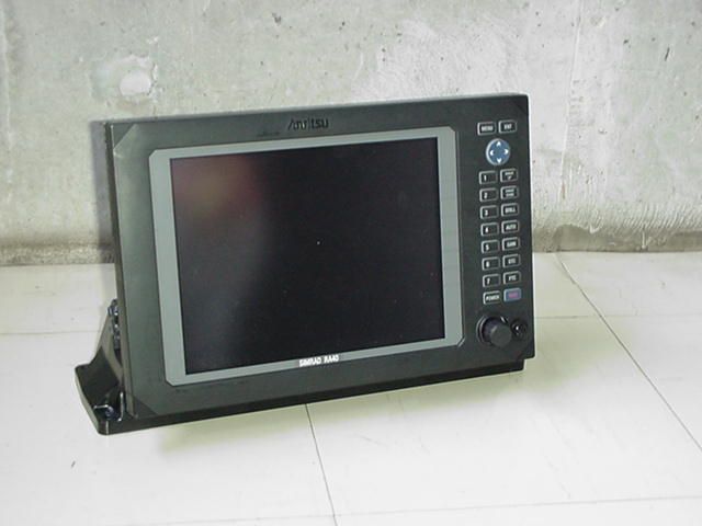
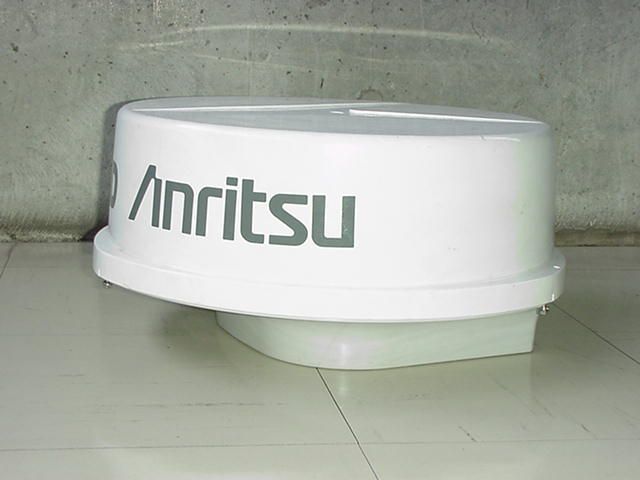
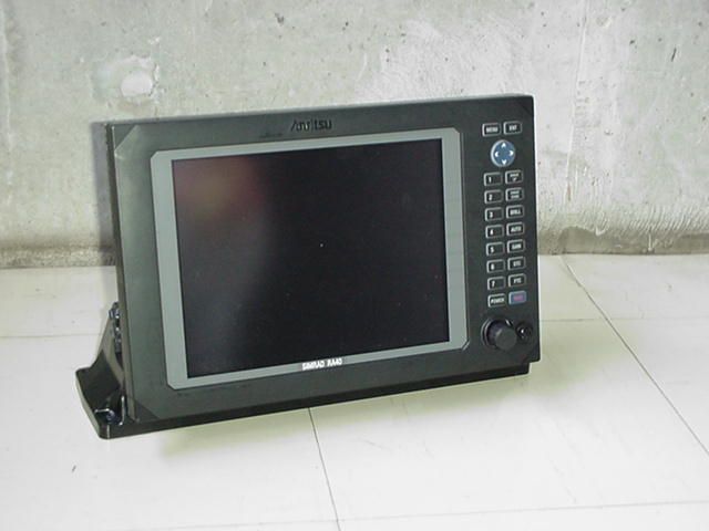
- Marine Radar RA775UA
- Frequency Range
- 9300.00000000 - 9500.00000000
- Company
- Anritsu Corporation
- Country
- Japan
Documents & Files
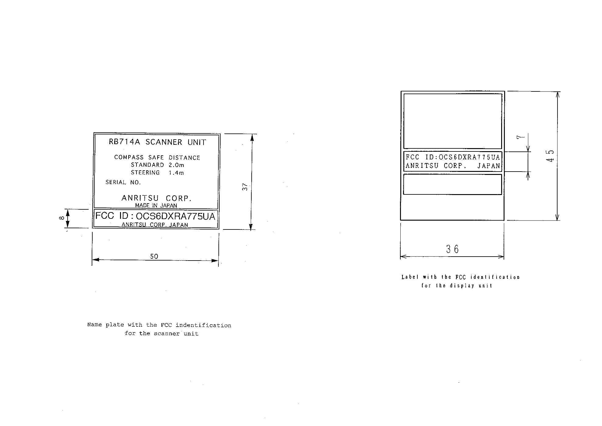
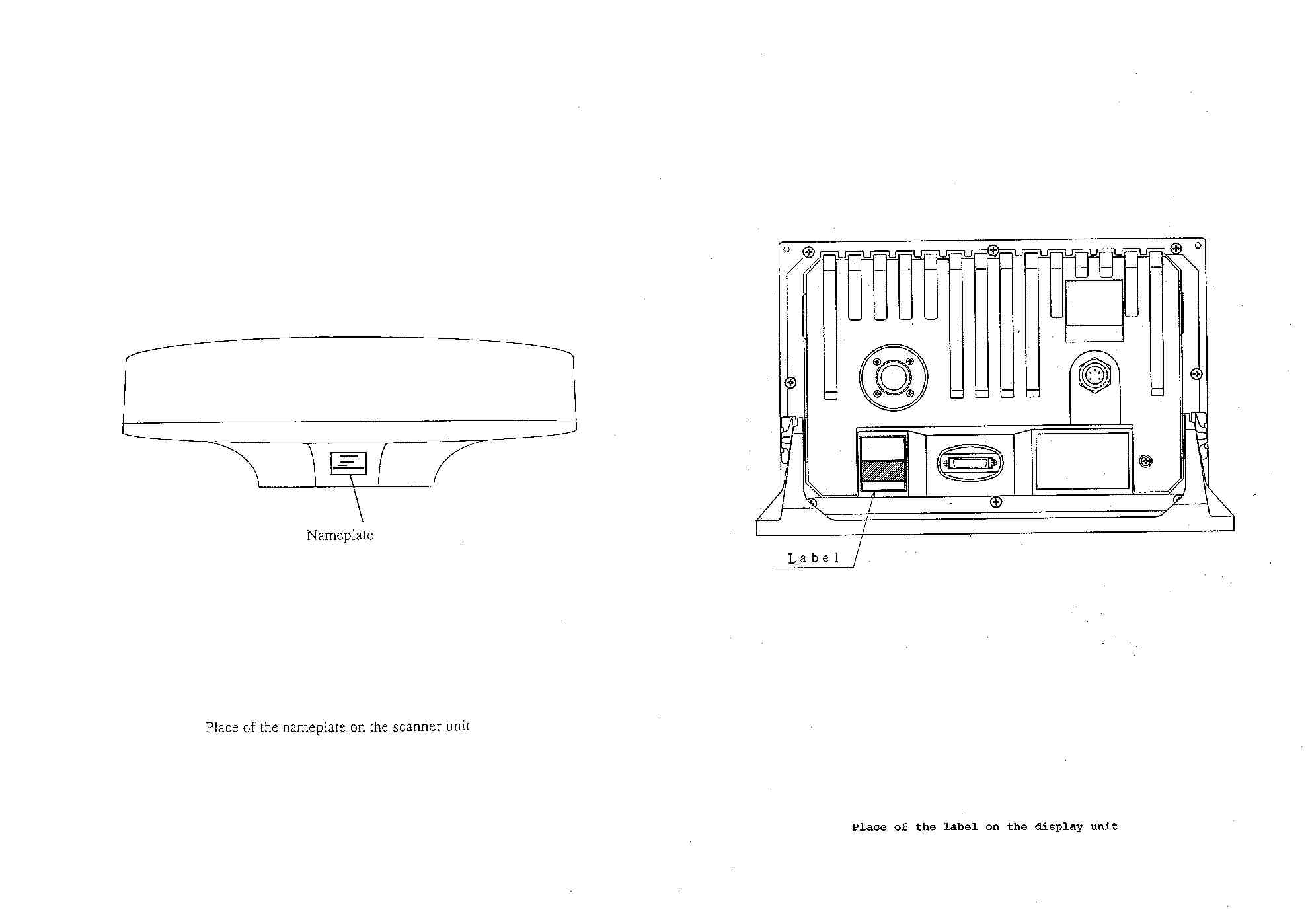
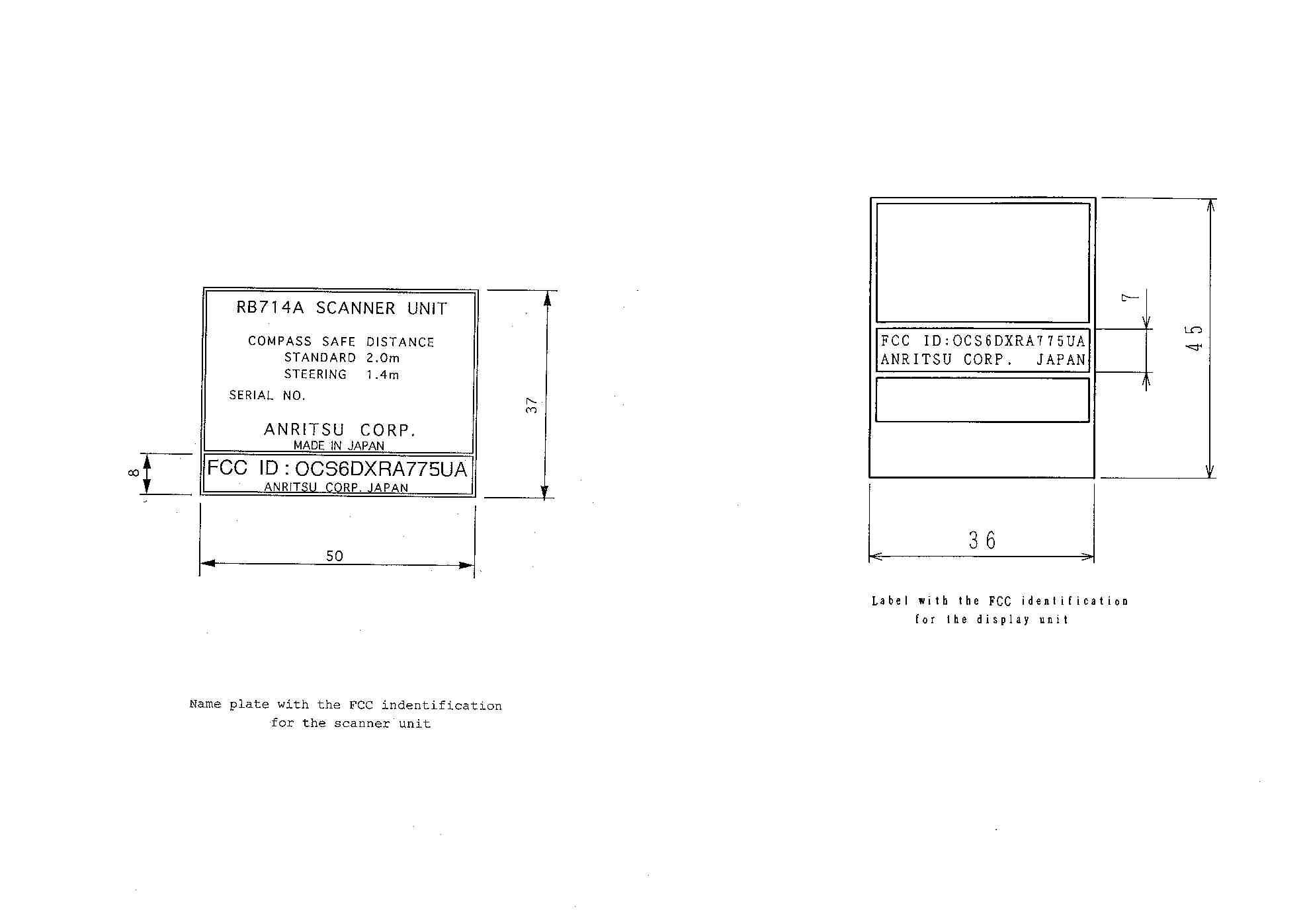
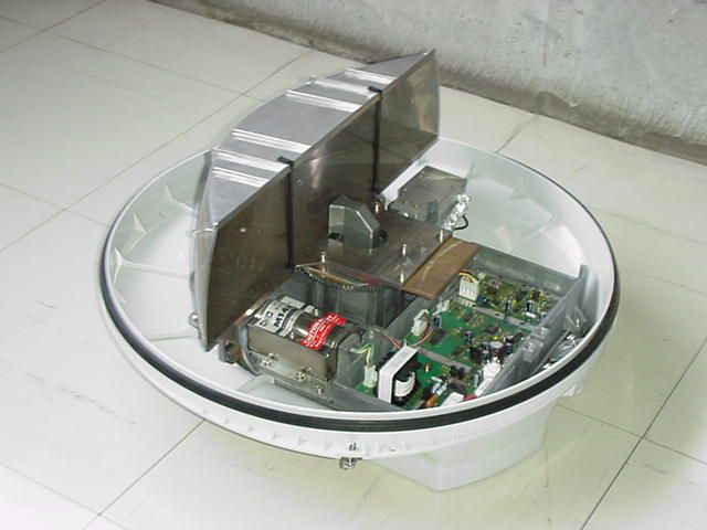
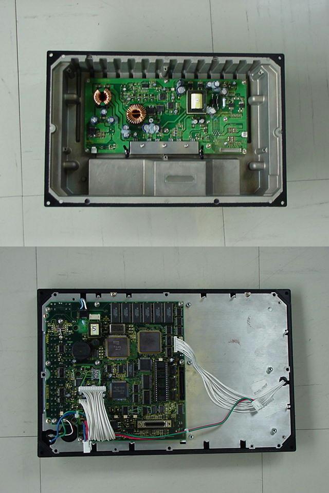
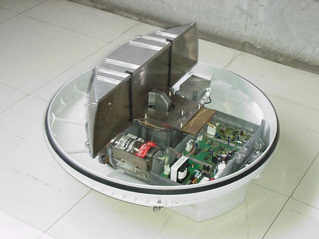
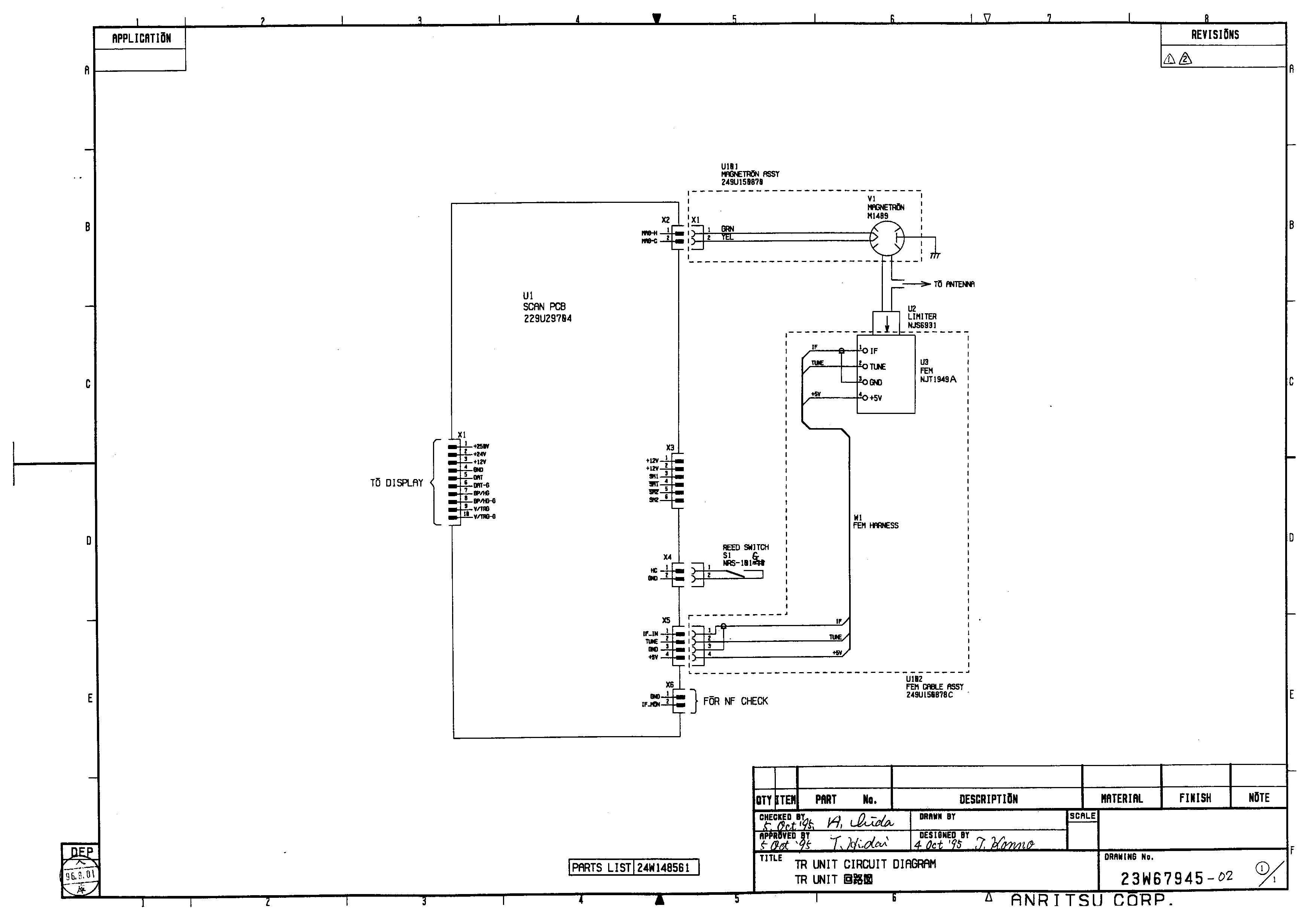
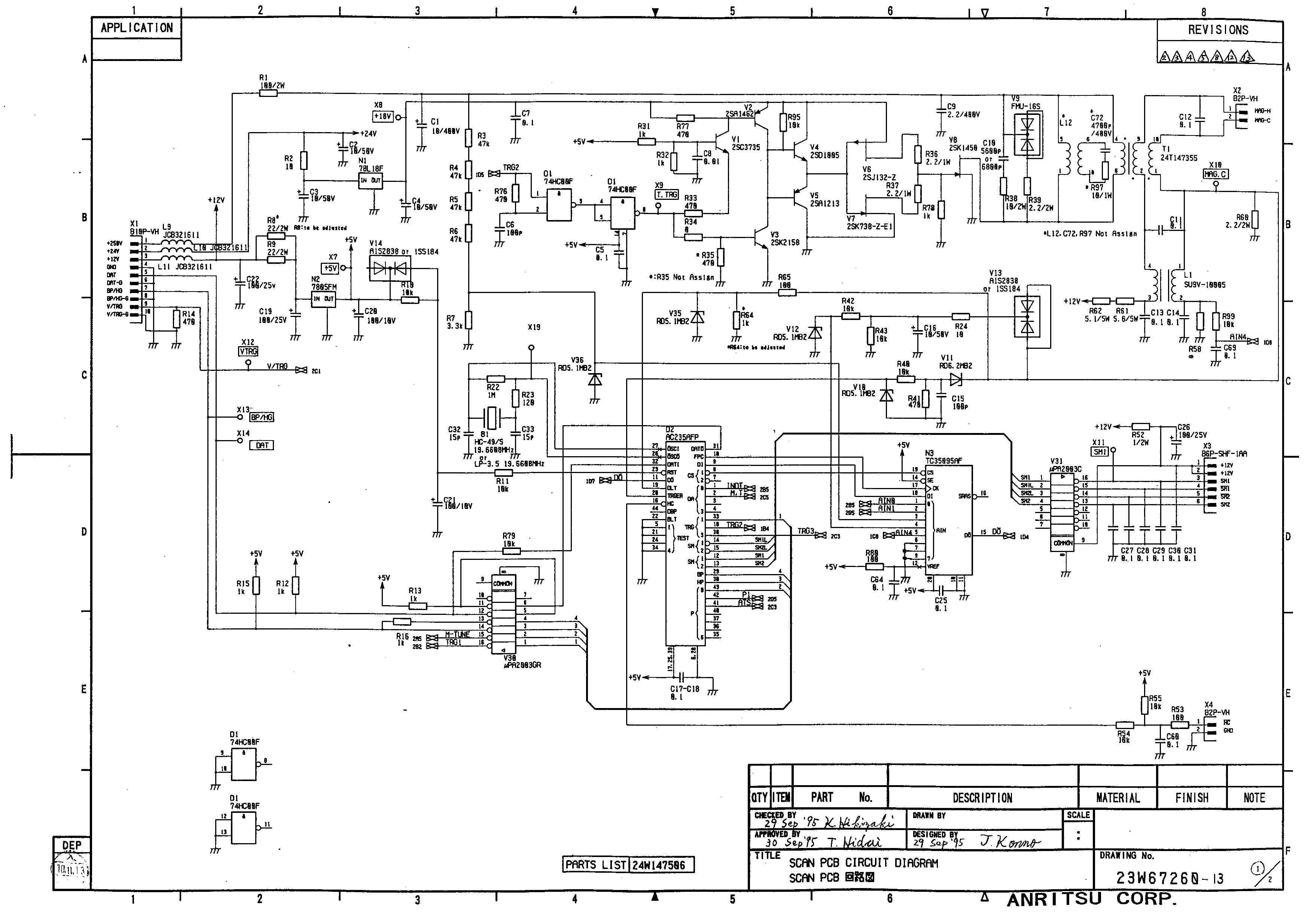
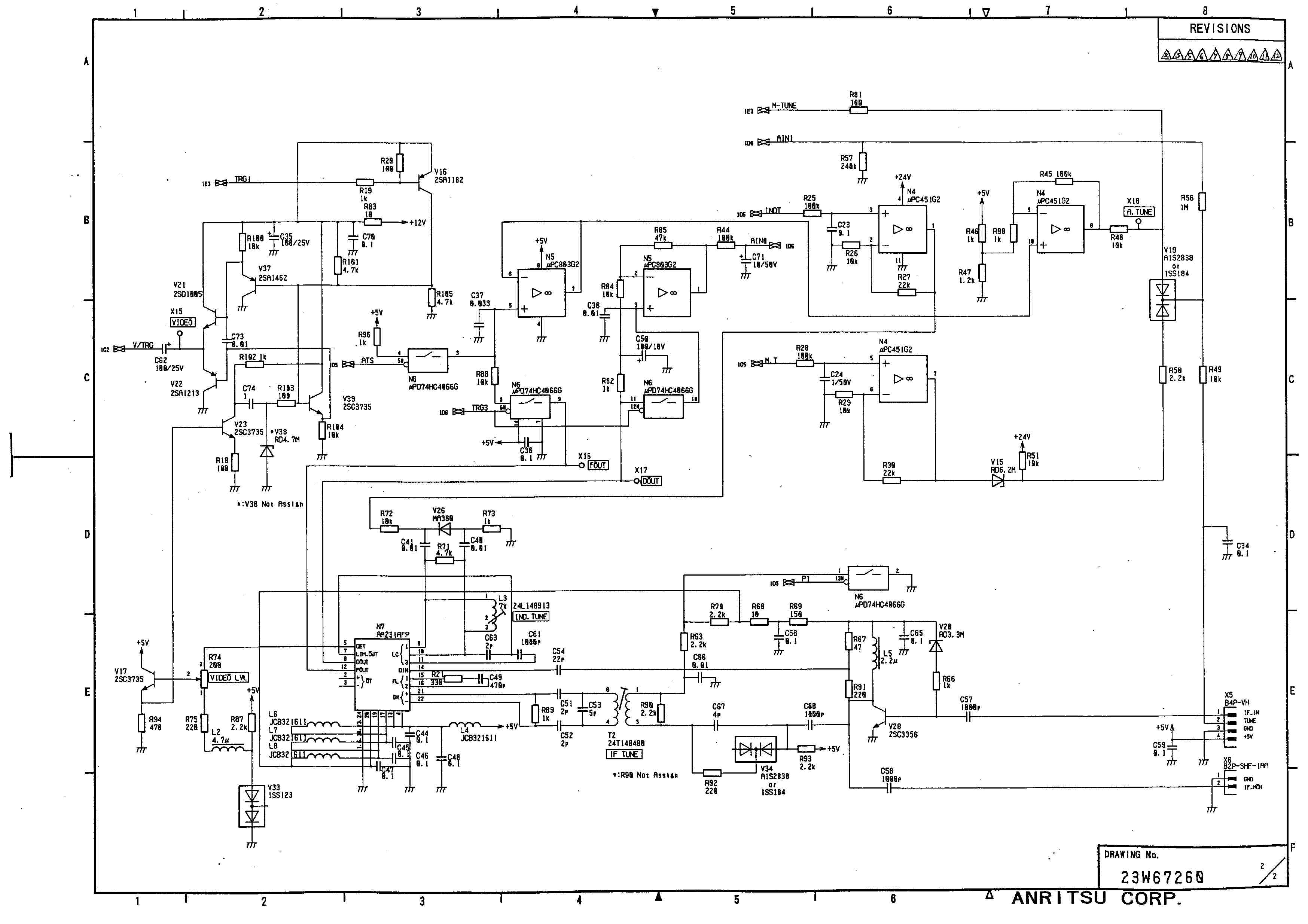
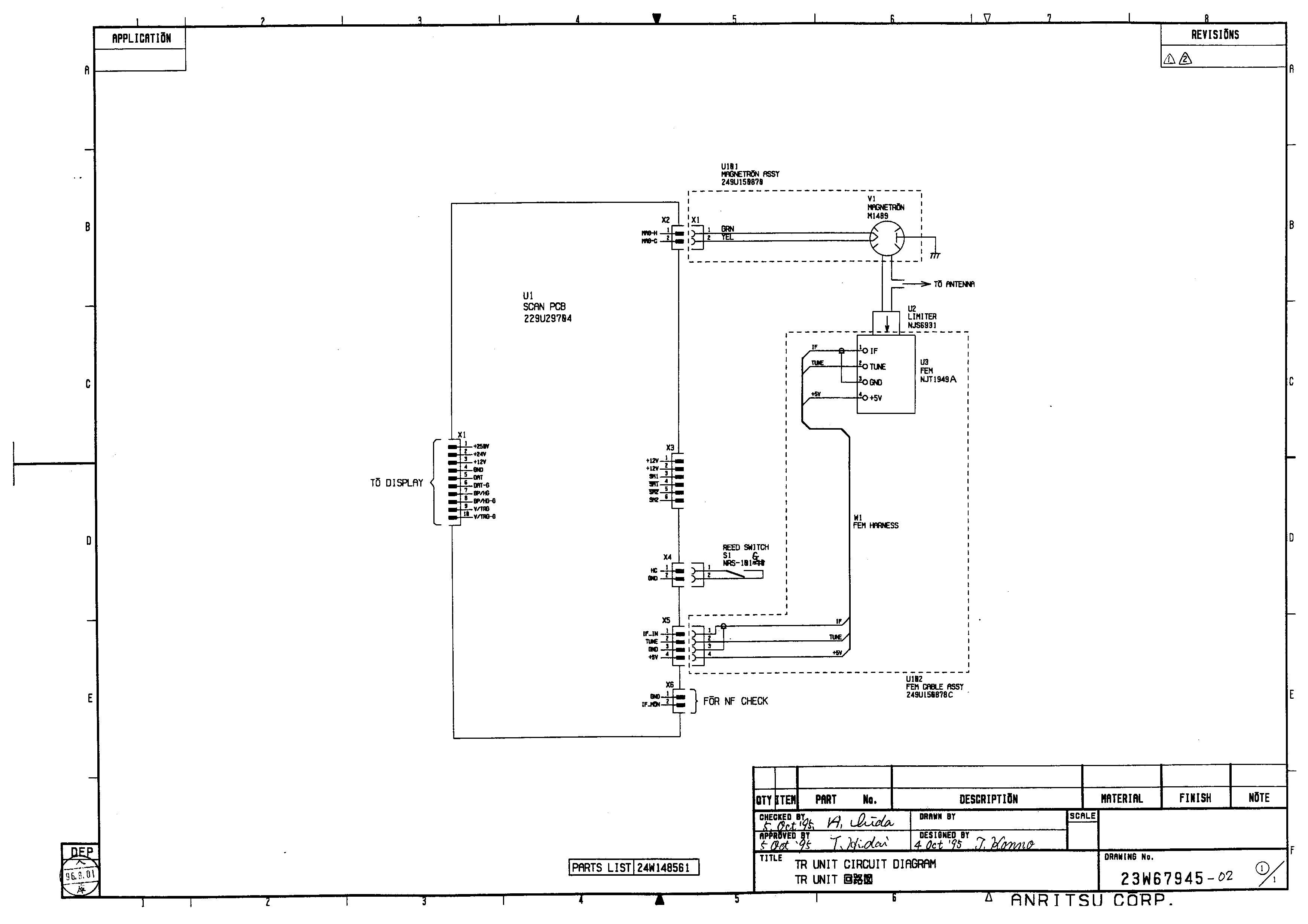
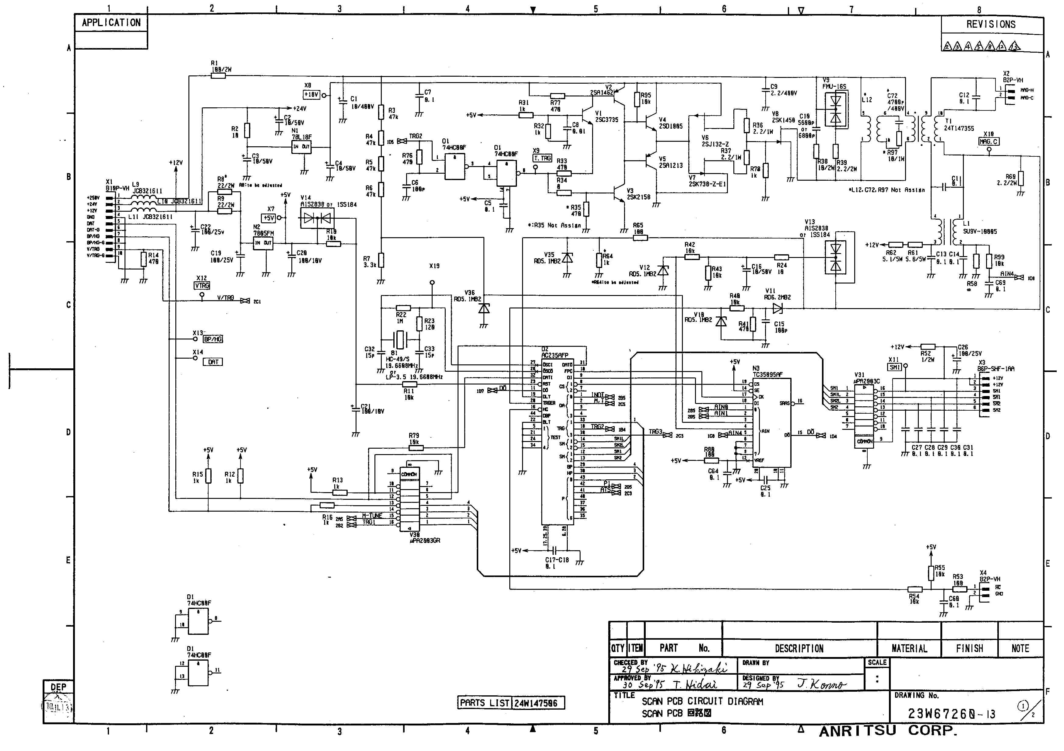
Document Text
Text extracted from the exhibit documents filed with the FCC. Open a document above to read the original.
Users Manual
RA775UA Marine Radar Instruction Manual 2nd Edition Communication Systems Division Information & Communications Group ANRITSU CORPORATION Document : E-A775UA-2-01 • Read this manual before using the equipment. • Keep this manual. To prevent the risk of personal injury or damage to the equipment, Anritsu Corporation uses the following safety symbols to indicate safety-related information. Insure that you clearly understand the meanings of the symbols BEFORE using the equipment. Symbols Used in Manual This indicates a very dangerous procedure that could result in serious injury or death if not performed properly. This indicates a hazardous procedure that could result in se- rious injury or death if not performed properly. This indicates a hazardous procedure or danger that could result in light-to-severe injury, or that might damage the equipment, if proper precautions are not taken. Safety Symbols Used on Equipment The following safety symbols are used inside or on the equipment near operation loca- tions to provide information about safety items and operation precautions. Insure that you clearly understand the meanings of the symbols and take the necessary precau- tions BEFORE using the equipment. This indicates high voltages with a risk of serious electric shock if the part is touched. NEVER touch the part with bare hands, etc. The symbol prohibits the operation shown inside the symbol. (The example in the left prohibits disassembly.) The symbol indicates that the operation inside the symbol is potentially hazardous. (The example on the left indicates that the plug should be held when disconnecting it from the AC outlet.) This indicates the ground (earth) terminal. If the equipment cannot be grounded via the power cord, connect this terminal to ground. There is a risk of serious electric shock if the equipment is not grounded. RA775UA Marine Radar Instruction Manual 25th Aug. 1999 (2nd Edition) 14th July. 1999 (1st Edition) Copyright © 1999, ANRITSU CORPORATION. All right reserved. No part of this manual may be reproduced without the prior written per- mission of the publisher. The contents of this manual may be changed without prior notice. Printed in Japan Safety Symbols DANGER ! WARNING ! CAUTION ! : 10W/m 2 : 1.8m ÅThere is a risk of receiving electric shock if these parts are touched by accident. Only qualified personnel should remove covers on these parts. ÇTo avoid accidental antenna rotation, turn off ship’s main and pull off out the motor fuse during repair inspect, or maintenance. When repairing or inspecting the scanner unit wear a safety harness and provide a secure platform so that there is no danger of falling even when the vessel lists or when there is an unexpected incident such as an earth quake. ÉDo not approach the antenna while it is transmitting. In addition, at inspection never look into the wave guide during trans- mission. ÑWhen remove the scanner cover etc., do not drop it. It may endanger people below. ÖDo not paint the RADOME. Antenna performance will be down. For Safety ÅSee instruction manuals before connecting power. Safety information is written in. ÇEarth connection essential before connecting supply. There is a risk of serious electric shock if the equipment is not grounded. ÉThere is a risk of receiving electric shock if these parts are touched by accident. Only qualified personnel should remove covers on these parts. Installation Radio laws dictate that this radar may only be installed by properly licensed personnel. Licensing You must obtain a license as prescribed by the Radio Law to operate this unit. Exporting According to the sales agreement with your distributor, this product is for use only within your country. When taking it overseas, there may be cases where you must obtain export permission. Contact Anritsu Corporation or one of our dealers as soon as possible if you are planning to take the product out of your country. Equipment Certificate Anritsu Corporation certifies that this equipment was tested before shipment, to meet recog- nized standards. Warranty Anritsu Corporation warrants this equipment to be manufactured in accordance with pub- lished specifications and free from defects in materials and/or workmanship. Anritsu Corporation will repair or exchange any parts except consumable parts proven to be malfunctioning under normal use for a period of two (2) years. This warranty policy shall not cover any labor charge. Limitation of Warranty Anritsu Corporation’s warranty policy does not apply to product which has been subjected to accident, abuse, or misuse, shipping damage, alterations, corrosion, incorrect and/or unau- thorized service or modification, or product which the serial number plate has been altered or removed. ANRITSU CORPORATION MAKES NO WARRANTIES, EITHER EXPRESS OR IMPLIED, EXCEPT AS PROVIDED HEREIN, INCLUDING WITHOUT LIMITATION PARTICULAR PURPOSE OR USE, OR AGAINST INFRINGE- MENT OF ANY PATENT. IN NO EVENT SHALL ANRITSU BE LIABLE FOR ANY DIRECT, INCIDENTAL OR CONSEQUENTIAL DAMAGES OF ANY NATURE, OR LOSSES OR EXPENSES RESULTING FROM ANY DEFEC- TIVE PRODUCT OR THE USE OF ANY PRODUCT. Should you have queries about maintenance, please contact our distributor. To Customers * To use this equipment effectively, the operation and maintenance procedure in this manual must be followed properly. Note that this equipment is only a navigational instrument having no warrant for navigation safety. Non-execution of fundamental navigation requirements such as the ship location check or lookout is not allowed. * If some abnormality occurs in this equipment, immediately turn off the equipment POWER switch and the radar main switch in the power distribution board and notify our maintenance section or dealer. * This instrument uses oscillator and LCD backlight. They are easy to be broken. Do not sub- ject the instrument to excessive force or drop it. * The mercury (Hg) is used in LCD backlight. When you discard your radar, it is due to laws…
Text truncated - open the document above for the full version.
Users Manual
RA775UA Marine Radar Instruction Manual 2nd Edition Communication Systems Division Information & Communications Group ANRITSU CORPORATION Document : E-A775UA-2-01 • Read this manual before using the equipment. • Keep this manual. To prevent the risk of personal injury or damage to the equipment, Anritsu Corporation uses the following safety symbols to indicate safety-related information. Insure that you clearly understand the meanings of the symbols BEFORE using the equipment. Symbols Used in Manual This indicates a very dangerous procedure that could result in serious injury or death if not performed properly. This indicates a hazardous procedure that could result in se- rious injury or death if not performed properly. This indicates a hazardous procedure or danger that could result in light-to-severe injury, or that might damage the equipment, if proper precautions are not taken. Safety Symbols Used on Equipment The following safety symbols are used inside or on the equipment near operation loca- tions to provide information about safety items and operation precautions. Insure that you clearly understand the meanings of the symbols and take the necessary precau- tions BEFORE using the equipment. This indicates high voltages with a risk of serious electric shock if the part is touched. NEVER touch the part with bare hands, etc. The symbol prohibits the operation shown inside the symbol. (The example in the left prohibits disassembly.) The symbol indicates that the operation inside the symbol is potentially hazardous. (The example on the left indicates that the plug should be held when disconnecting it from the AC outlet.) This indicates the ground (earth) terminal. If the equipment cannot be grounded via the power cord, connect this terminal to ground. There is a risk of serious electric shock if the equipment is not grounded. RA775UA Marine Radar Instruction Manual 25th Aug. 1999 (2nd Edition) 14th July. 1999 (1st Edition) Copyright © 1999, ANRITSU CORPORATION. All right reserved. No part of this manual may be reproduced without the prior written per- mission of the publisher. The contents of this manual may be changed without prior notice. Printed in Japan Safety Symbols DANGER ! WARNING ! CAUTION ! : 10W/m 2 : 1.8m ÅThere is a risk of receiving electric shock if these parts are touched by accident. Only qualified personnel should remove covers on these parts. ÇTo avoid accidental antenna rotation, turn off ship’s main and pull off out the motor fuse during repair inspect, or maintenance. When repairing or inspecting the scanner unit wear a safety harness and provide a secure platform so that there is no danger of falling even when the vessel lists or when there is an unexpected incident such as an earth quake. ÉDo not approach the antenna while it is transmitting. In addition, at inspection never look into the wave guide during trans- mission. ÑWhen remove the scanner cover etc., do not drop it. It may endanger people below. ÖDo not paint the RADOME. Antenna performance will be down. For Safety ÅSee instruction manuals before connecting power. Safety information is written in. ÇEarth connection essential before connecting supply. There is a risk of serious electric shock if the equipment is not grounded. ÉThere is a risk of receiving electric shock if these parts are touched by accident. Only qualified personnel should remove covers on these parts. Installation Radio laws dictate that this radar may only be installed by properly licensed personnel. Licensing You must obtain a license as prescribed by the Radio Law to operate this unit. Exporting According to the sales agreement with your distributor, this product is for use only within your country. When taking it overseas, there may be cases where you must obtain export permission. Contact Anritsu Corporation or one of our dealers as soon as possible if you are planning to take the product out of your country. Equipment Certificate Anritsu Corporation certifies that this equipment was tested before shipment, to meet recog- nized standards. Warranty Anritsu Corporation warrants this equipment to be manufactured in accordance with pub- lished specifications and free from defects in materials and/or workmanship. Anritsu Corporation will repair or exchange any parts except consumable parts proven to be malfunctioning under normal use for a period of two (2) years. This warranty policy shall not cover any labor charge. Limitation of Warranty Anritsu Corporation’s warranty policy does not apply to product which has been subjected to accident, abuse, or misuse, shipping damage, alterations, corrosion, incorrect and/or unau- thorized service or modification, or product which the serial number plate has been altered or removed. ANRITSU CORPORATION MAKES NO WARRANTIES, EITHER EXPRESS OR IMPLIED, EXCEPT AS PROVIDED HEREIN, INCLUDING WITHOUT LIMITATION PARTICULAR PURPOSE OR USE, OR AGAINST INFRINGE- MENT OF ANY PATENT. IN NO EVENT SHALL ANRITSU BE LIABLE FOR ANY DIRECT, INCIDENTAL OR CONSEQUENTIAL DAMAGES OF ANY NATURE, OR LOSSES OR EXPENSES RESULTING FROM ANY DEFEC- TIVE PRODUCT OR THE USE OF ANY PRODUCT. Should you have queries about maintenance, please contact our distributor. To Customers * To use this equipment effectively, the operation and maintenance procedure in this manual must be followed properly. Note that this equipment is only a navigational instrument having no warrant for navigation safety. Non-execution of fundamental navigation requirements such as the ship location check or lookout is not allowed. * If some abnormality occurs in this equipment, immediately turn off the equipment POWER switch and the radar main switch in the power distribution board and notify our maintenance section or dealer. * This instrument uses oscillator and LCD backlight. They are easy to be broken. Do not sub- ject the instrument to excessive force or drop it. * The mercury (Hg) is used in LCD backlight. When you discard your radar, it is due to laws…
Text truncated - open the document above for the full version.
Cover Letter(s)
From: Brian G. Vlad, Simrad Inc. Sent: Thursday, January 27, 2000 To: www.fcc.gov Subject: Re: FCC ID OCS6DXRA775UA / EA94804 Dear Sir or Madam: With respect to the above application for equipment authorization, I would like to remove the request for confidentiality . Thank you in advance for your cooperation. Sincerely, Brian G. Vlad, Simrad Inc.
Operational Description
Operational Description MARINE RADAR RA775UA 2 1. A description of all circuitry and devices provided determining and stabilizing frequency. Rule's No. 2.983(d)-(10) 1.1 The oscillating frequency stability of pulsing magnetron depends upon the load characteristics. In this radar, the load of the magnetron consists of a duplexer, a waveguide feeder and an antenna, and the load is matched to the magnetron. The VSWR of the load is better than 1.25 within the specified frequency range. 1.2 Receiver The oscillating frequency stability of FET local oscillator depends upon the supply voltage and ambient temperature. For obtaining the desired frequency stability of oscillator, following means are provided. In addition this radar equips an automatic tuning circuit to coincide the receiver frequency with the transmission frequency. 1.2.1 Temperature compensation High Q strip line of the oscillator circuitry is employed in the Front-End module due to temperature compensation. 1.2.2 Stabilizing the power supply DC voltage supplied to the FET local oscillator is stabilized by the regulator. DC voltage across the varactor diode for tuning is supplied from a D/A converter. The voltage across the D/A converter is made by dividing the regulated 24 volts DC. The regulated voltage is generated by regulator on power supply unit. Therefore stable oscillation can be obtained. 2. A description of any circuits or devices employed for suppression of spurious radiation , for limiting modulation, and for limiting the operating power. Rule's No. 2.983(d)-(11) 2.1 Circuits or devices employed for suppression of spurious radiation. 2.1.1 Suppression of spurious radiation from antenna A duplexer, a waveguide feeder and an antenna perform the narrow band-pass filter and all the spurious signals outside the radar 3 frequency band are suppressed -50dB lower than main radiation level. 2.1.2-1 Line filters The line filters are provided on the ship's power supply line as follows; Line filter L4 and capacitors C1-C4,C18-C19,C68-C69 and C77 on POWER PCB in the display unit. 2.1.2-2 Special interunit connection cable A special 12 cores cable shielded by the metal braid is employed for the interunit connection and the grounding of the braid are made surely at both ends. 2.2 Circuits or devices for limiting the modulation and operating power Transmitting tube, pulsing magnetron, operates with negative going high voltage pulse in the modulator. DC 250 volts as the modulator source generated by the DC-DC converter with voltage regulator(power supply unit) is supplied to the modulator to generate the modulating pulse with constant amplitude. Accordingly, modulation and transmitter power level are maintained constant.
Operational Description
Operational Description MARINE RADAR RA775UA 2 1. A description of all circuitry and devices provided determining and stabilizing frequency. Rule's No. 2.983(d)-(10) 1.1 The oscillating frequency stability of pulsing magnetron depends upon the load characteristics. In this radar, the load of the magnetron consists of a duplexer, a waveguide feeder and an antenna, and the load is matched to the magnetron. The VSWR of the load is better than 1.25 within the specified frequency range. 1.2 Receiver The oscillating frequency stability of FET local oscillator depends upon the supply voltage and ambient temperature. For obtaining the desired frequency stability of oscillator, following means are provided. In addition this radar equips an automatic tuning circuit to coincide the receiver frequency with the transmission frequency. 1.2.1 Temperature compensation High Q strip line of the oscillator circuitry is employed in the Front-End module due to temperature compensation. 1.2.2 Stabilizing the power supply DC voltage supplied to the FET local oscillator is stabilized by the regulator. DC voltage across the varactor diode for tuning is supplied from a D/A converter. The voltage across the D/A converter is made by dividing the regulated 24 volts DC. The regulated voltage is generated by regulator on power supply unit. Therefore stable oscillation can be obtained. 2. A description of any circuits or devices employed for suppression of spurious radiation , for limiting modulation, and for limiting the operating power. Rule's No. 2.983(d)-(11) 2.1 Circuits or devices employed for suppression of spurious radiation. 2.1.1 Suppression of spurious radiation from antenna A duplexer, a waveguide feeder and an antenna perform the narrow band-pass filter and all the spurious signals outside the radar 3 frequency band are suppressed -50dB lower than main radiation level. 2.1.2-1 Line filters The line filters are provided on the ship's power supply line as follows; Line filter L4 and capacitors C1-C4,C18-C19,C68-C69 and C77 on POWER PCB in the display unit. 2.1.2-2 Special interunit connection cable A special 12 cores cable shielded by the metal braid is employed for the interunit connection and the grounding of the braid are made surely at both ends. 2.2 Circuits or devices for limiting the modulation and operating power Transmitting tube, pulsing magnetron, operates with negative going high voltage pulse in the modulator. DC 250 volts as the modulator source generated by the DC-DC converter with voltage regulator(power supply unit) is supplied to the modulator to generate the modulating pulse with constant amplitude. Accordingly, modulation and transmitter power level are maintained constant.
Parts List/Tune Up Info
Operational Description MARINE RADAR RA775UA 2 1. A description of all circuitry and devices provided determining and stabilizing frequency. Rule's No. 2.983(d)-(10) 1.1 The oscillating frequency stability of pulsing magnetron depends upon the load characteristics. In this radar, the load of the magnetron consists of a duplexer, a waveguide feeder and an antenna, and the load is matched to the magnetron. The VSWR of the load is better than 1.25 within the specified frequency range. 1.2 Receiver The oscillating frequency stability of FET local oscillator depends upon the supply voltage and ambient temperature. For obtaining the desired frequency stability of oscillator, following means are provided. In addition this radar equips an automatic tuning circuit to coincide the receiver frequency with the transmission frequency. 1.2.1 Temperature compensation High Q strip line of the oscillator circuitry is employed in the Front-End module due to temperature compensation. 1.2.2 Stabilizing the power supply DC voltage supplied to the FET local oscillator is stabilized by the regulator. DC voltage across the varactor diode for tuning is supplied from a D/A converter. The voltage across the D/A converter is made by dividing the regulated 24 volts DC. The regulated voltage is generated by regulator on power supply unit. Therefore stable oscillation can be obtained. 2. A description of any circuits or devices employed for suppression of spurious radiation , for limiting modulation, and for limiting the operating power. Rule's No. 2.983(d)-(11) 2.1 Circuits or devices employed for suppression of spurious radiation. 2.1.1 Suppression of spurious radiation from antenna A duplexer, a waveguide feeder and an antenna perform the narrow band-pass filter and all the spurious signals outside the radar 3 frequency band are suppressed -50dB lower than main radiation level. 2.1.2-1 Line filters The line filters are provided on the ship's power supply line as follows; Line filter L4 and capacitors C1-C4,C18-C19,C68-C69 and C77 on POWER PCB in the display unit. 2.1.2-2 Special interunit connection cable A special 12 cores cable shielded by the metal braid is employed for the interunit connection and the grounding of the braid are made surely at both ends. 2.2 Circuits or devices for limiting the modulation and operating power Transmitting tube, pulsing magnetron, operates with negative going high voltage pulse in the modulator. DC 250 volts as the modulator source generated by the DC-DC converter with voltage regulator(power supply unit) is supplied to the modulator to generate the modulating pulse with constant amplitude. Accordingly, modulation and transmitter power level are maintained constant.
Parts List/Tune Up Info
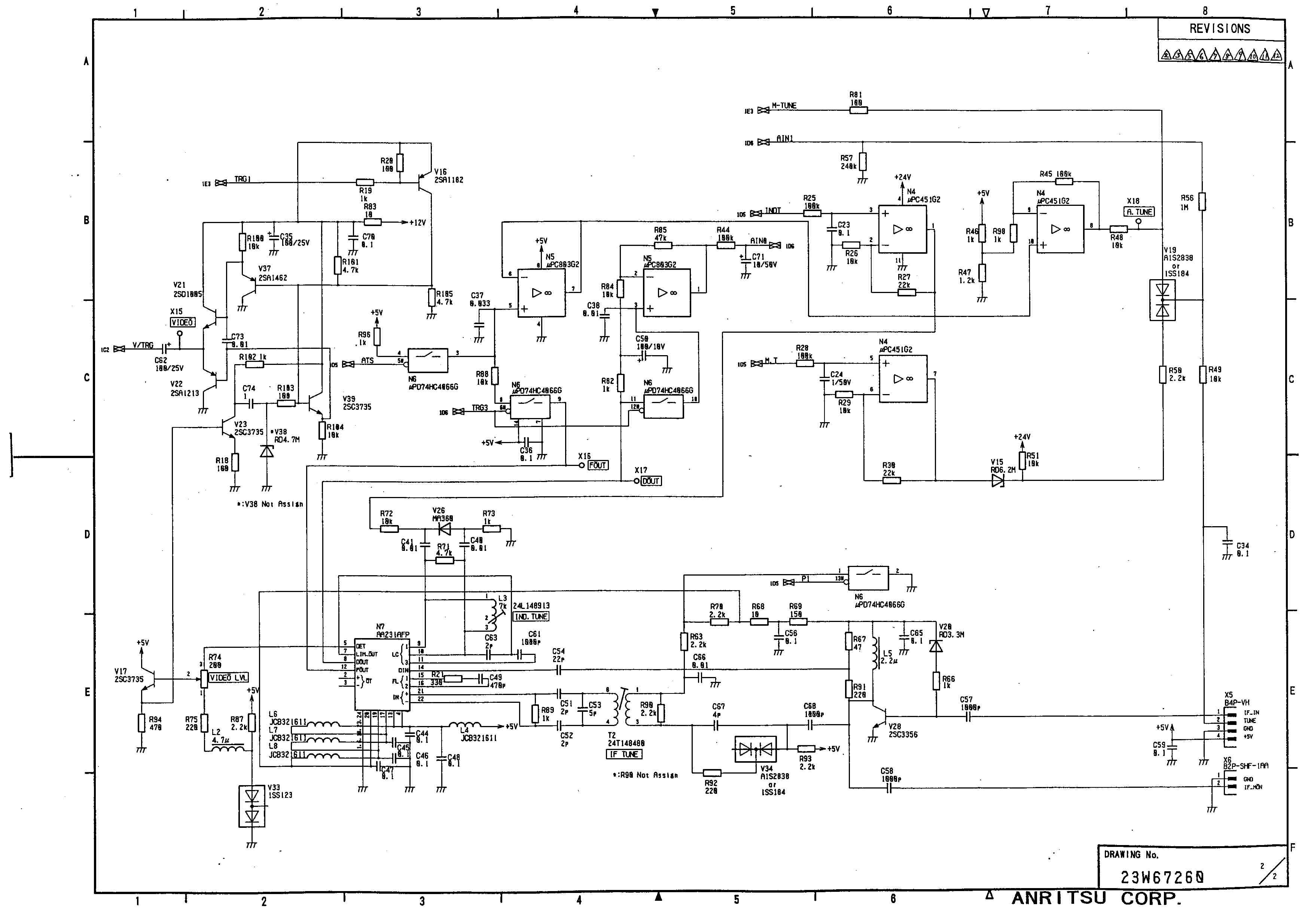
Parts List/Tune Up Info MARINE RADAR RA775UA 2 Technical description that is not described on FCC Form 731 and an attached instruction book for Type RA775UA. 1. Function of each electron tube, semiconductor or other active circuit device Rule's No.2.983 (d) - (6) 1.1 Electron tubes Symbol No.DescriptionTypeFunction V1MagnetronM1489Transmitting tube 1.2 Semiconductor in the chassis of the scanner unit Symbol No.DescriptionTypeFunction U2Limiter diodeNJS6931Receiver protector at X-band U3Front end with X-band amplifier NJT1959RF amplifier, local oscillator and mixer 1.3Semiconductoron SCAN PCB Symbol No.DescriptionTypeFunction D1IC74LS00FQuadruple 2 input AND D2ICAC235AFPScanner controller N1IC78L18FVoltage regulator N2IC7805FMVoltage regulator N3ICTC35095AF8ch A/D converter N4ICuPC451G2Dual Op-amp N5ICuPC803G2Dual Op-amp N6ICuPD74HC4066 G Analog switch N7ICAA231AFPLogarithmic amplifier V1,V3Transistor2SC3735Pulse amplifier V2Transistor2SC1462Pulse amplifier V4Transistor2SC2712Switching high voltage 3 V5Transistor2SA1154Switching high voltage Symbol No.DescriptionTypeFunction V6FET2SJ132-ZFET for the switching high voltage V7FET2SK738-Z-E1FET for the switching high voltage V8FET2SK1450Switching high voltage V9DiodeFMU-16SDamping diode V10,V12Zener diodeRD5.1MBRectifier for magnetron current V11Zener diodeRD6.2MBRectifier for magnetron current V13Diode1SS184Rectifier for magnetron current V15Zener diodeRD6.2MBHold off diode V16Transistor2SA1182Amplifier V19Diode1SS184Switching of Tuning V20Zener diodeRD3.3MBLimiter V21Transistor2SD1005Output buffer for video V22Transistor2SA1213Amplifier V23Transistor2SC3735Buffer amplifier V24Diode1SS123Output buffer for video V26Diode1SV222Temperature compensator V28Transistor2SC3356Pre-amplifier V30ICuPA2003GRSeptuple transistor array V31ICuPA2003CSeptuple transistor array V32Zener diodeRD4.7MBLimiter of trigger V33Diode1SS123Temperature compensator V34Diode1SS184Switching of band width V35,V36Zener diodeRD5.1MBLimiter 4 1.4 Semiconductor in the chassis of the display unit Symbol No.DescriptionTypeFunction H1LCD moduleLM64P302LCD display U1EncoderRECW20D-50- 201-1D Encoder 1.5 Semiconductor of MAIN PCB Symbol No.DescriptionTypeFunction D1-D2,D24,D26IC74HC541FOctal 3-state buffer D3ICAC233CFPGraphic memory controller D4ICuPD72020GC- 8-3B6 Graphic controller D5-D8,D13-D14ICVRAM2M70J256kX8 VRAM D9-D12IC74HC166F8-bit shift register D15ICSRAM32KX8- 12CF 32kX8 SRAM D16ICHD6413003TF1 6 16bit CPU D17-D18IC74HC138FDecoder D19,D28IC74HC273FOctal D-flip-flop D20ICEPROM256kX1 6-12C 256kX16 EPROM D21IC24LC04B/SN512kX8FRAM D22IC74HC74FDual D-flip-flop D23,D39IC74HC14FSchmitt-trigger inverter D25,D33IC74HC245FOctal bus transceivers D27IC74HC05FHex. Inverter D29-D30IC74HC595F8-bit shift register D31ICMB89251A-PFSerial data transmitter/Receiver D32IC74HC123FDual Multivibrators D34ICTC35095AF8ch A/D converter 5 Symbol No.DescriptionTypeFunction D35ICAC232CFPVideo signal processor D36ICHM62832HJP- 25 32kX8 SRAM D37ICMC14046BFPhase locked loop D38ICuPD485505G- 25 Line buffer D40IC74HC74FDual D-flip-flop K1-2,4-6Photo couplerTLP181BLIsolator K3Photo couplerPC356TIsolator N1ICTL7759CPSVoltage detector N2-5ICTHS124Hole IC N6,N9ICuPC451G2Quadruple Op-amp N7IC78L05FVoltage regulator N8ICMB88346BPF12ch 8bit D/A converter N10ICAA239BFPVideo controller V1FET2SK1419Switch V2Thyristor03P2JOver current protector V3Zener diodeRD10MB2Voltage regulator V4DiodeDF10LC20UVoltage protector V5,V36TransistorUN211FBuffer amplifier V6-V7,V39- V40,V43 Diode1SS123Switching diode V8,V10- V11,V17- V18,V25 Diode1SS184Switching diode V9,V34TransistoruPA2003GRTransistor array V12Zener diodeRD5.1MB2Voltage regulator V13,V19,V22,V2 6,V38,V42 TransistorUN221LBuffer amplifier V14Transistor2SA1213CFL amplifier V15-V16Transistor2SD1000CFL amplifier 6 V20-V21Transistor2SC2712Buffer amplifier Symbol No.DescriptionTypeFunction V23,V27-V33LEDTLG260Illuminator V24Transistor2SA1213Buffer amplifier V35Transistor2SD1000Trigger amplifier V37Transistor2SB799Output buffer for video V41FET2SK2158Switch 1.6 Semiconductor of POWER PCB Symbol No.DescriptionTypeFunction D1ICTC4011BF(N)Quadruple 2 input NAND K1Photo couplerTLP181BLIsolator K2Photo couplerPC356TIsolator N1-2ICuPC494GSwitching controller N3ICuPC1093TVoltage regulator V1Transistor2SC2873Voltage regulator V2,V19-V20,Transistor2SC2712Buffer amplifier V3,V8DiodeDE5SC6M- 4061 Rectifier V4-V5DiodeD1FL20U-4063Rectifier V6-V7DiodeRU4ARectifier V9,V11Zener diodeRD20MB2Voltage protector V10Zener diodeRD10MB2Voltage regulator V12,V14,V17,V2 2 Transistor2SA1213Buffer amplifier V13,V15,V18,V2 6 DiodeD1FS4-4063Switching diode V16,V25,V28FET2SK1419Switch V21Transistor2SC2873Buffer amplifier V23-V24FET2SK2010Switch 7 V27Transistor2SA1162Switch V29Transistor2SB1097Voltage regulator Symbol No.DescriptionTypeFunction V30-V31Transistor2SC2712Voltage regulator V32,V42Zener diodeRD5.1MB2Voltage regulator V33TransistorUN221LBuffer amplifier V34-V36DiodeDF10LC20U- 4062 Voltage protector V37Transistor2SC3631-ZSwitch of H.T. V38TransistorUN2113Buffer amplifier V39DiodeA1SS123Switching diode V40Transistor2SA1413-ZSwitch of H.T. V41Transistor2SA1213Switch of H.T. 8 2. Tune up procedure over the power range or at specific operating power levels. Rule's No. 2.983(d)-(9) 2.1 Transmitter Pulse radars employ a pulse-excited magnetron as the transmitter tube. The magnetron used in this radar has a fixed cavity resonator which determines the oscillating frequency. Accordingly, this radar transmitter has no more frequency-adjust circuitry. 2.2 Receiver Pulse radars receive the reflected signal from targets, therefor receiving signal has the same frequency as the transmitter power output. Thus, the radar receiver is tuned to the transmitting frequency. This radar has a super heterodyne type receiver with a Front-End module. The Front-End module consists of a GaAs FET low noise amplifier, a double balanced mixer and a FET local oscillator. Tuning of the receiver is accomplished by controlling the …
Text truncated - open the document above for the full version.
Contact Information
Applicant
Yasuyuki Oishi(R&D Engineer)
Technical Contact
Anritsu Corporation, Atsugi FactoryYuji Sekine
[email protected]+81-462-96-6592
1800, Onna, Atsugi-shi · Kanagawa · Japan
Non-Technical Contact
Anritsu Corporation, Americas DivisionHiroshi Miki
[email protected]+81-3-3473-7203
Technical Specifications
| # | Rule Parts | Frequency Range | Power Output | Emission |
|---|---|---|---|---|
| 1 | 80 | 9.30 GHz - 9.50 GHz | 2000 W | 68M8P0N |
Other Applications from Anritsu Corporation
OCS-MT1100A
Oct 08, 2014Network Master Flex
Equipment Class
DSS - Part 15 Spread Spectrum Transmitter
OCS-MT1000A
Jun 24, 2014Network Master Pro
Equipment Class
DSS - Part 15 Spread Spectrum Transmitter
OCS6DXRA774UA
Apr 28, 1999Marine Radar RA774UA
Equipment Class
MRD - Marine Radar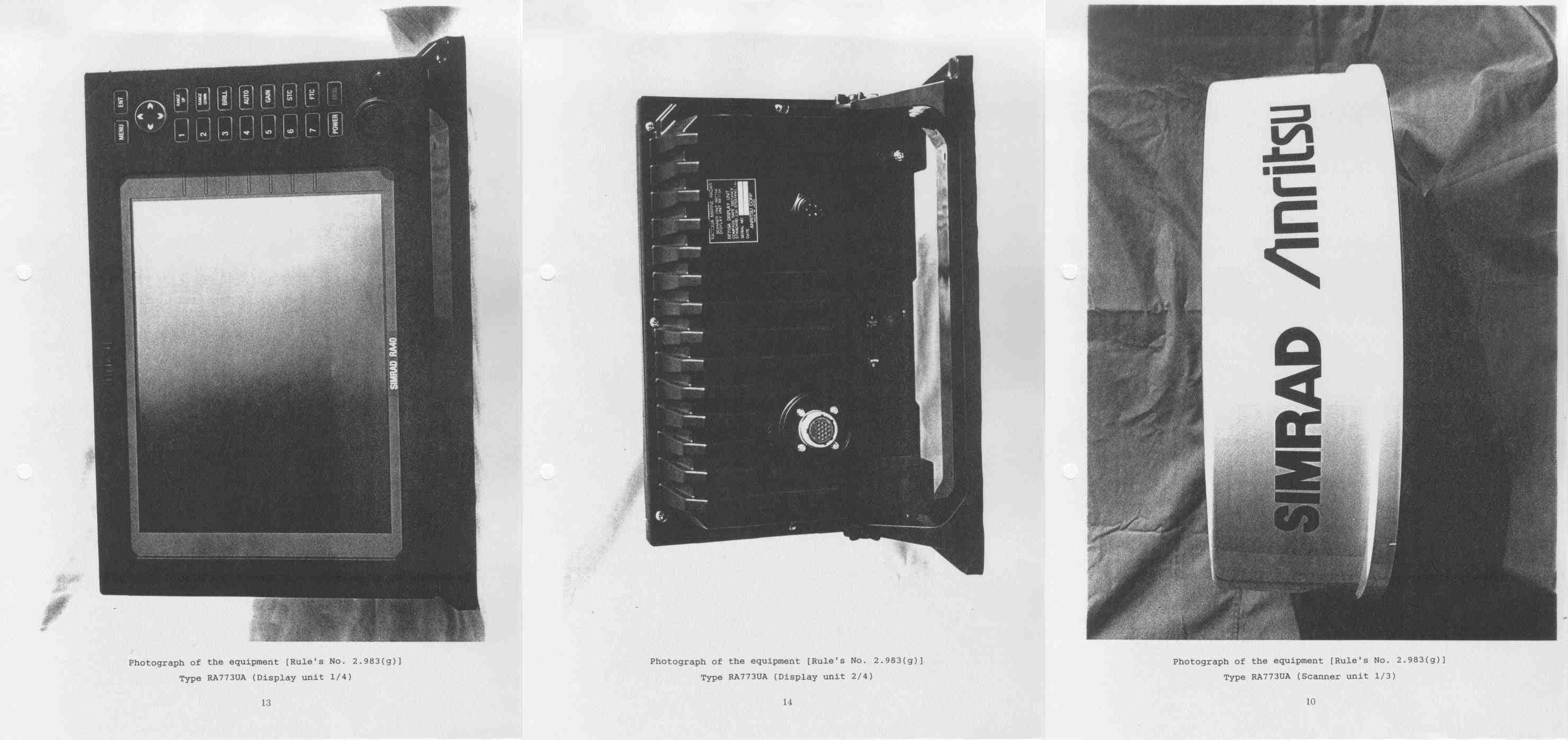
OCS6DXRA773UA
Mar 30, 1999Marine Radar RA773UA
Equipment Class
MRD - Marine Radar