ODGWWC1000Restaurant Wireless Data Management System
Hantel Co., Ltd.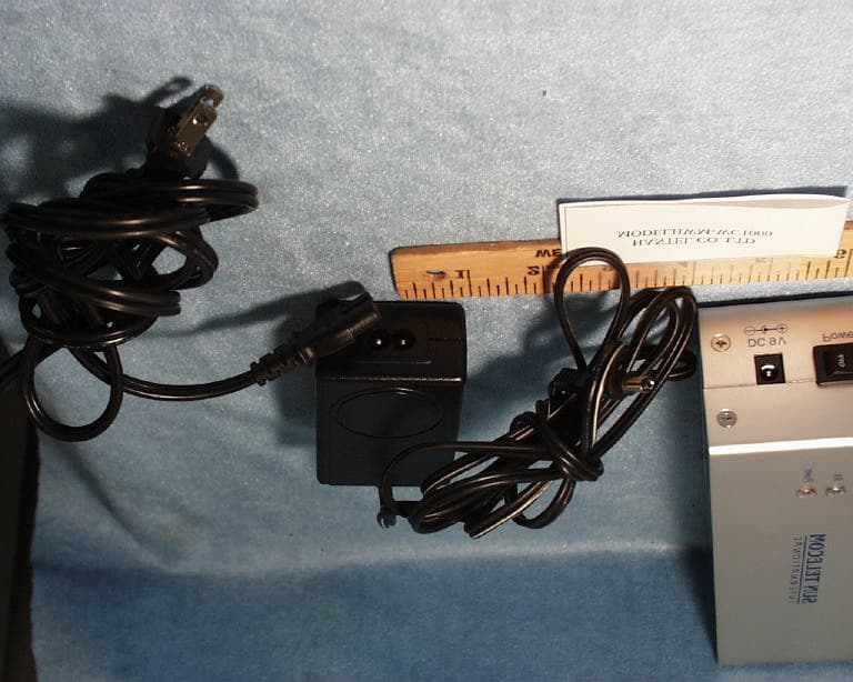
Click to zoom
Application Details
- Equipment Class
- TNB - Licensed Non-Broadcast Station Transmitter
- Date of Grant
- Jul 25, 2002
- Application Purpose
- Original Equipment
- Date of Application
- Jul 25, 2002
- Equipment Note
- Restaurant Wireless Data Management System
- Frequency Range
- 457.57500000 - 457.57500000
- Company
- Hantel Co., Ltd.
- Country
- South Korea
Documents & Files
Document Text
Text extracted from the exhibit documents filed with the FCC. Open a document above to read the original.
Users Manual
- Table of Contents - 1. What is Expeditor? 2. Expeditor Components 3. How to install Expeditor 4. Specifications 5. How to use The Expeditor 6. Troubleshooting 7. How to set up delay timing for Table Unit 8. Table Unit Delay timer set up 9. How to set up Chef Unit addresses 10. Warnings 1. What is The EXPEDITOR? EXPEDITOR is a system designed to transfer data within a limited area such as a restaurant. This unique system increases the servers ability to service customers. This is done through increasing the efficiency of the server. . EXPEDITOR Components. 1. Main Unit – Unit Body-1 ea, Antenna-2 ea, Bracket-4 ea, Screw (small) for Bracket-8 ea (3*8mm) Screw (Big) for fix-4 ea (4*20mm), Foot (rubber) for Housing-4 ea (20*20*3mm) 2. Chef Unit – Unit Body-1 ea, Antenna –1 ea, Bracket-4 ea, Screw (small) for Bracket-8 ea (3*8mm) Screw (Big) for fix-4 ea (4*20mm), Foot (rubber) for Housing-4 ea (20*20*3mm) 3. Table Unit- Unit Body-50 ea, Menu Boards-50 ea, AAA batteries-150 ea. 4. Server Unit- Server Units-5 ea, AAA batteries -5 ea, Server band-5 ea, Holder-5 ea, Chain-1 ea, Server Unit Manual – 1 ea. 5. EXPEDITOR Operations Manual - 1 ae. How to Install Expeditor. 1. Main Unit Install brackets to Main Unit using the small screws. The brackets are installed to the sides of the Main Unit. After installing mounting brackets to Main Unit, the unit can be mounted to the wall. Connect the 9V/1.5A power transformer to the Main Unit using the barrel connector end of the power supply. Connect the other end of the power transformer to a standard 110v wall outlet. 2. Chef Unit 1) Install brackets to Main Unit using the small screws. The brackets are installed to the sides of the Main Unit. After installing mounting brackets to Main Unit, the unit can be mounted to the wall. 2) Connect the 9V/300-500mA power transformer to the Main Unit using the barrel connector end of the power supply. Connect the other end of the power transformer to a standard 110v wall outlet Table Unit 1) Install 3 x AAA batteries in accordance with instructions on the bottom of the unit body. Install Menu board to the top of the Table Unit body. Turn power switch to ON located on bottom of unit body. . Server Unit 1) Install Server Unit batteries located on the back side of the unit. The Server Unit can be worn in the server band or can be worn in a holster. The server band is an elastic wrist watch type band that allows the server easy access to the Server Unit especially when the servers hands are full. The holster allows the Server Unit to be clipped to a piece of clothing. Specifications 1. Main Unit 1) The Main Unit controls the flow of messaging traffic within the establishment. The Main Unit receives requests from the Chef/Management Unit and the Table Unit and transmits them to the appropriate Server Unit. 3. Table Unit 1) The Table Unit has menu options labeled 1-6. When one of these options are selected, the request is sent to the Main Unit along with the Table Unit address. The Main Unit will send the request to the appropriate Server Unit. 4. Chef/Management Unit 1) The Chef/Management sends a request to the Main Unit. The Main Unit sends the request along to the appropriate Server Unit. This will notify the Server that their food is ready for pick up. 5. Server Unit The Server Unit receives requests sent to it by the Main Unit. The Main Unit transfers requests from both the Table Unit and the Chef/Management units. 5. Specification EXPEDITOR Units Specifications MAIN CHEF TABLE SERVER Frequency 450 ~ 470 MHz Freq. Stability 5 ppm Data Rate 1200 bps Output Power 100 mW 10 mW 5 mW Max. Trans. Protocol FSK 2 Level POCSAG PLL Frequency PLL Synthesizer Batt. AAA 3 AAA 1 Ext. Power 9V/1.5A SMPS 9V 1.5A Dimension 236*200*200 174*260*50 95*133*43 Mm Transmit/Receive Transmit/Receive Transmit/Receive Transmit/Receive Receive only . Main Unit 1) Plug the 9V/1.5A adaptor into any 110v wall outlet. Once the unit is plugged into the power supply, the red LED 9V Indicator will light. 2) Turn the power switch to ON. This switch is located on the bottom of the Main Unit body. This will cause the red LED 5V Indicator to be lit. When data is sent from the Table Unit a GREEN data LED will blink. 4) Once a request is sent from a Table Unit or an order information is sent from a Chef/Management Unit, the Main Unit controls the flow of this information and sends it to the proper Server Unit. Below is a diagram of the flow of information through the Main Unit. (Data transmission diagram) Chef/Management Unit 1) Plug the 9V/1.5A adaptor into any 110v wall outlet. Once the unit is plugged into the power supply, the red LED 9V Indicator will light. 2) Turn the power switch to ON. This switch is located on the bottom of the Main Unit body. This will cause the red LED 5V Indicator to be lit. 3) When a specific order is ready for a specific server, that servers button should be pressed. This will send a notification to the specific Server Unit that an order is ready to be retrieved in kitchen. There is an OPTIONAL Group Call on the Chef/Management Unit allowing the Kitchen Staff or Management to send a message to all Server Units simultaneously. Table Unit 1) Three AAA batteries are provided with each unit. These should be installed in accordance with the instructions located in the battery well of the unit located on the bottom of the main body. 2) As shown below, the Menu Board lists the Server Call options. Individual establishments have the option of altering these option displays. <Table Unit Button Function> No. 1 : Ready to Order No. 2 : Need more Drinks No. 3 : Need more Bread No. 4 : Need Silverware/ Napkin No. 5 : Need Assistance No. 6 : Check please 3) Once a data selection is chosen by the customer, the Green LED lights up the show that Data is being sent. The Table Unit sends the data and the Server Unit address information to the Main Unit. The Main Unit will send the information to the Server Unit assigned to this specific table…
Text truncated - open the document above for the full version.
Cover Letter(s)
From: Steve Cheng Sent: Friday, July 26, 2002 5:47 PM To: Mike Kuo Cc: Christine Vu Subject: RE: HANTEL CO., LTD, FCC ID:ODGWWC1000, AN02T2115 Dear Mike, Please see our response right below each question. Thanks. Question #1: Please provide emission designator and necessary bandwidth ( justify with 2M+2DK rules). Response: Emission designator is 2M+2DK=2(1200bps/2)+2(9kHz/2)=10.2K. Emission designator is 10K2F1D. Question #2: User manual does not include RF exposure warning statement. Please provide revised user manual to comply this requirements. Response: User manual had been revised to include the RF exposure warning statement. Please refer to new uploaded manual. Question #3: EUT is requesting to certify under Part 90 of FCC rules. However, EUT label indicates this device comply with Part 95 of rules. Please provide correct FCC ID label format. ID label has been corrected, please refer to new up loaded ID label. Steve Cheng -----Original Message----- From: CERTADM Sent: Friday, July 26, 2002 5:32 PM To: '[email protected]' Subject: HANTEL CO., LTD, FCC ID:ODGWWC1000, AN02T2115 Notice_content ------------- Question #1: Please provide emission designator and necessary bandwidth ( justify with 2M+2DK rules). Question #2: User manual does not include RF exposure warning statement. Please provide revised user manual to comply this requirements. Question #3: EUT is requesting to certify under Part 90 of FCC rules. However, EUT label indicates this device comply with Part 95 of rules. Please provide correct FCC ID label format. Question #4: What is the channel bandwidth that is used by this device ? As indicated in page 6 of test report, the channel bandwidth is 25kHz but the plot shown on page 21 showed 16.83kHz. Please explain. Best Regards Mike Kuo / TCB Certifier The items indicated above must be submitted before processing can continue on the above referenced application. Failure to provide the requested information within 60 days of the original e-mail date may result in application dismissal and forfeiture of the filing fee. Also, please note that partial responses increase processing time and should not be submitted. Any questions about the content of this correspondence should be directed to the e-mail address listed below the name of the sender.
ID Label/Location Info
FCC ID LABEL Hantel Co., LTD. This device complies with Part 90 of the FCC Rules. FCC ID: ODGWWC1000 FCC ID LABEL
Operational Description
HWM-WC1000 TABLE OF CONTENTS INTRODUCTION ------------------------------------------------ .System Overview and Components System Overview Components .Installation .Circuit Description - Main Digital Board - Rx Module - Tx Module .Tune up Procedure .Electrical specification System Overview The products have been developed for quick & stable service to customers in restaurants. HWM-WC1000 consists of RX Module, Main Digital Board, and TX Module. Functionally RX Module receives data from Table Unit, Main Digital Board process the data, and TX Module pages to each Pager by Pocsag protocol Components The basic System component are : l HWM-WC1000 l Antenna l Power Adapter Main Unit Installation Using an enhanced screw above 3M heights, Fix HWM-WC1000 Also HWM-WC1000 needs power cable within 3M for power supply. . 1. Assemble the antenna like “a” in picture 2-1. “b” “a” PICTURE 2-1 2. Connecting the power adapter to power cable, Insert D/C output to D/C port like ‘b’ in picture 2-1. 3. Turn Main Unit power switch on. When power is supplied, power lamp turns on. When Main Unit receives data from Table Unit ( HWM-TT1000 ), RX Lamp turns on. When Main Unit transfers data to Pager, TX Lamp turns on. Technical Circuit Description ( HWM-WC1000 ) 1 Main Logic Board UD1 ( 80C32 ) 80C32 is compatible with 80c51 in pin composition (8bit Micro controller), but 80c32 uses external ROM instead of internal ROM.. It processes data received from 89LV52 of Table Unit & Server Call Unit. All the data is processed by Pocsag Encoding, transferred to Pager Unit by wireless, and transferred to Host Unit by RS-232C. 80C32 use port 0, & port 2 for address bus, and port 0 for data bus. So, port 0 (pin 32~39) is used for being placed above 8bit(A0~A7) of address, and for data bus (D0~D7). Port 2(pin21~280) is used for being placed below 8bit(A8~a15) of address. Also, using 74HC373(Octal 3-state latches) from external, divide data bus and address bus. As clock signal, used for ALE(Address Latch Enable, pin 30) to active high, When interfaced with external memory component, it is used for being placed below address to latch. U1 ( 89LV52 ) Possesses the same characteristics as 80C32, the system, used 2 of RX Main Unit. The transferred data From Table Unit & SCU, divide channel and receive independently. Received data from each channel through error check, and pass DS1609(Dual Port RAM) to transfer to TX 80C32 of HWM-WC1000 UD3 ( M27C512 ) Eprom(Erasable Electrically Programmable Read Only Memory) 27C512 supports UV (Ultra Violet erase) & OTP(One Time Programmable). This is supported 45ns access Time, and had 8 of in/output and 64Kbyte. Main function of Eprom M27C512, input actual program of HWM-WC1000 and operate as external program memory of 80C32. As clock, to active low PSEN(Program Strobe Enable) and read data from external program memory PSEN is printed 2 times in each Machine Cycle, port 0 is used for address in ALE Falling Edge. Also, 8Kbyte internal Rom is inside 8052 but to connect EA(External Access Enable, pin 31) with ground for using 64Kbyte External Program Memory. UD4 ( 62256 ) External Data Memory 62256 has 8 of in/ouput and 32Kbyte as SRAM(Static Random Access Memory). It is used for operating external RAM. Until A 0 ~ A 13, has input address, and until , I/O 7 ~ I/O 0 has 8 data bus. /OE(out Enable) is connected 8052 /RD, and operates when active low. Also, /WE (Write Enable) pin is connected 8052 /WD, and write when active low. All of the work can operate when /CS(Chip Select) low. UD6 ( 8255 ) It calls PPI(Programmable Peripheral Interface), and common in/ output LSI for using with Intel Micro Processor. 8255 has 8bit of in/output port of 3 port(A,B,C), for lack of 80C32 port to easily control in outside. Total 24bit port divide group A(port A, port C 4 ~ C 7 ) and group B(port B, port C 0 ~ C 3 ) to independently setup operating mode( mode0, mode1, mode2). To decide & control print port to using A 0 , A 1 , CS(Chip Select) UD11 ( DS1609 ) DS1609 is 256byte Dual Port RAM, receiving SCU & Table unit data from RX part 89LV52 of HWM- WC1000 are used when transferred to HWM-WC1000-TX part 80C32. Also it use a buffer. It has 2 asynchronous address/data bus. Each port is controlled by /OE(Output Enable, /WE(Write Enable), /CE(Port Enable). AD 0 ~ AD 7 are Port address/data. UD7 ( 93C66 ) E 2 PROM 93C66 has 255~word*16bit. This is for when power is off, saving information before power off and initial information. Can read & write data anytime by electrical signal, CS means Chip Select Input, SK means Serial Clock Input, DI means Serial Data Input, DO means Serial Data Output. UD9 ( MAX-232 ) This component is for communicating with Host Unit & RS232C. It can change 5V Digital Level to 12V RS 232C or reverse it. UD5 ( 74HC138 ) 74HC138 is Memory Decoder/Demultiplexer CMOS, for expanding lack port of 80C32 to use 80C32 address and generating CE(Chip Enable) signal to control in/output data of 8255, 62256 or DS1609. It controls active low Output(Y 0 ~ Y 7 ) by A 0 ~ A 2 3bit Input. The condition is Chip Enable Pin CS 1 High, and CS 2 & CS 3 Low. UD2 ( 74HC373 ) When it interfaces External Memory, controlled signal of address bus is needed, data bus, /RD and /WR, From 80C32, port0, port2 are used address bus, to need port 0 for data bus But, 80C32 port 0 used together address bus & data bus so, to use 74HC373 (Octal 3-state Latch) from outside, and latch printing address before data. Finally, can use dividing address & data. That time clock signal use ALE. . D 0 ~ D 7 are Data Input, Q 0 ~ Q 7 are Non-Inverting Output 2 RX Unit LNA The frequency from antenna only pass range of saw filter F1(DF430)-430MHz +/-4MHz and amplify gain from LNA circuit Q7,Q8 L1,C3,R1,C4. Local Circuit ( PLL Synthesizer , Data Modulation .Loop ) PLL is consists of 3 parts, from Main Board UD1, frequency data input to PLL IC 11,12 and 13 pin. PLL IC is received frequency from reference crystal (X1) 12.8MHz and divided 12.5KHz by reference…
Text truncated - open the document above for the full version.
Parts List/Tune Up Info
. Tune up Procedure l RX RF PLL LOCK-IN VOLTAGE ALIGNMENT Check a TP7 with Scope probe or Voltage meter, set 1.5V by tuning VC2. LOCAL FREQUENCY ALIGNMENT Check a Q1’s base pin with spectrum measuring probe, align local frequency by tuning VC3. l TX RF (in Test Mode) PLL LOCK-IN VOLTAGE ALIGNMENT Check a TP3 with Scope probe or Voltage meter, set 2.5V by tuning VC2. TX FREQUENCY ALIGNMENT Check output signal’s frequency, align TX signal’s frequency by tuning VC1. MODULATION RATE ALIGNMENT Check output signal’s modulation rate, align TX signal’s modulation rate to 9KHz by tuning VR2. . Electrical specification MAIN TX Module 1. Output Power : 100 mW Max 2. Frequency Stability : 1.5 ppm / Year 3. Frequency Stability VS Temperature : 2.5 ppm ( -10 ~ +50 oC ) 4. Modulation Characteristics : Fo to +/- 4.5KHz 5. Spurious Emissions at Antenna Terminals : MAIN RX Module 1. Sensitivity : -105 dbm 2. Adjacent-Channel Interference : 50 dB 3. Spurious rejection : 50 dB 4. Image rejection : 50 dB
RF Exposure Info
APPLICANT: HANTEL FCC ID: ODGWWC1000 MPE CALCULATION FOR 0 dBi ANTENNA Formula used in the MPE Calculations: E^2/3770 = S, mW/cm2 Pwatts*Ggain = 10^(PdBm-30+GdBi)/10) E, V/m = (Pwatts*Ggain*30)^.5/d, meters d = ((Pwatts*G*30)/3770*S))^0.5 --------- (A) Since S (mW/cm2) =0.30 from 1.1310 Table 1 P (dBm) = 22.50 EUT output power G (dBi) = 0.00 EUT antenna gain Substitute these parameters into the A above, we have MPE safe distance d (cm) = 6.87 NOTE: For mobile or fixed location transmitters, minimum separation distance is 20 cm, even if calculations indicate MPE distance is less
Test Report
FCC CFR47 PART 90 CERTIFICATION TEST REPORT FOR Restaurant Wireless Data Management System (Main Unit) (457.575MHz TRANSCEIVER) MODEL: HWM-WC1000 FCC ID: ODGWWC1000 REPORT NUMBER: 01I0892-1 ISSUE DATE: JULY 03, 2002 Prepared for HANTEL CO. LTD. 321-1 SHIN SUNG, B/D 2F, YANGJAE-DONG SEOCHO-KU KOREA Prepared by COMPLIANCE ENGINEERING SERVICES, INC. 561F MONTEREY ROAD, MORGAN HILL, CA 95037, USA TEL: (408) 463-0885 FAX: (408) 463-0888 REPORT NO: 01I0892-1 DATE: 07/03/02 FCC ID: ODGWWC1000 COMPLIANCE CERTIFICATION SERVICES Page 2 of 32 This report shall not be reproduced except in full, without the written approval of CCS. This document may be altered or revised by Compliance Certification Services personnel only, and shall be noted in the revision section of the document. TABLE OF CONTENT 1. VARIFICATION OF THE COMPLIANCE...................................................................................3 2. EUT DESCRIPTION.........................................................................................................................4 3. TEST METHODOLOGY..................................................................................................................4 4. TEST FACILITY...............................................................................................................................4 5. ACCREDITATION AND LISTING................................................................................................4 6. MEASURING INSTRUMENT CALIBRATION............................................................................4 7. APPLICABLE RULES AND BRIEF TEST RESULT...................................................................5 8. TEST SETUP, PROCEDURE AND RESULT..............................................................................11 8.1. OUTPUT POWER & SPURIOUS EMISSIONS.......................................................................11 8.2. EMISSIONS MASKS................................................................................................................15 8.3. BANDWIDTH LIMITATION...................................................................................................20 8.4. TRANSIENT FREQUENCY BEHAVIOR...............................................................................22 8.5. FREQUENCY STABILITY.......................................................................................................27 8.6. SETUP PHOTOS.......................................................................................................................30 REPORT NO: 01I0892-1 DATE: 07/03/02 FCC ID: ODGWWC1000 COMPLIANCE CERTIFICATION SERVICES Page 3 of 32 This report shall not be reproduced except in full, without the written approval of CCS. This document may be altered or revised by Compliance Certification Services personnel only, and shall be noted in the revision section of the document. 1. VARIFICATION OF THE COMPLIANCE COMPANY NAME: HANTEL CO. LTD. KOREA CONTACT PERSON: HOE-BUM KIM TELPHONE NO: (2) 571-4653 EUT DESCRIPTION: Restaurant Wireless Data Management System Main Unit MODEL NAME: HWM-WC1000 DATE TESTED: 02/23/02 – 02/28/02 & 07/03/02 TYPE OF EQUIPMENT INTENTIONAL RADIATOR EQUIPMENT TYPE 457.575MHz TRANSCEIVER MEASUREMENT PROCEDURE ANSI 63.4 / 1992, TIA/EIA 603 PROCEDURE CIRTIFICATION FCC RULE CFR 47 PART 90 Compliance Certification Services, Inc. tested the above equipment for compliance with the requirement set forth in CFR 47, PART 90-Private Land Mobile Radio Service. This said equipment in the configuration described in this report, shows the maximum emission levels emanating from equipment are within the compliance requirements. Warning : This document reports conditions under which testing was conducted and results of tests performed. This document may not be altered or revised in any way unless done so by Compliance Certification Services and all revisions are duly noted in the revisions section. Any alteration of this document not carried out by Compliance Certification Services will constitute fraud and shall nullify the document. Approved & Released For CCS By: Test By: STEVE CHENG THU CHAN MANAGER OF EMC DEPARTMENT SENIOR EMC ENGINEER COMPLIANCE CERTIFICATION SERVICES COMPLIANCE CERTIFICATION SERVICES REPORT NO: 01I0892-1 DATE: 07/03/02 FCC ID: ODGWWC1000 COMPLIANCE CERTIFICATION SERVICES Page 4 of 32 This report shall not be reproduced except in full, without the written approval of CCS. This document may be altered or revised by Compliance Certification Services personnel only, and shall be noted in the revision section of the document. 2. EUT DESCRIPTION The Expeditor is a fully programmable messaging system designed for the restaurant industry. The Expeditor can manage all communication traffic between the kitchen, servers, and guests. This system allows guests to send a specific request to the server just by pressing the button on their table unit. The chef unit feature enables the kitchen to page the server when an order is ready for pick up, saving the server unnecessary trips to the kitchen and insuring that the food is served fast and hot every time. The system keeps the service smooth and efficient, keeps the guest satisfied, and increases also table turnover. The basic system comes with built-in UHF transmitter that provides a superior coverage area (approximately 5,000 to 7,000 square feet). It is composed of 50 individual table messaging units, 10 server’s mobile units, one central processing unit, and one chef unit. 3. TEST METHODOLOGY Both conducted and radiated testing were performed according to the procedures documented on chapter 13 of ANSI C63.4 and FCC CFR 47 2.1046, 2.1047, 2.1049, 2.1051, 2.1053, 2.1055 and 2.1057. 4. TEST FACILITY The open area test sites and conducted measurement facilities used to collect the radiated data are located at 561F Monterey Road, Morgan Hill, California, USA. The sites are constructed in conformance with the requirements of ANSI C63.7, ANSI C63.4 and …
Text truncated - open the document above for the full version.
Test Setup Photos
REPORT NO: 01I0892-1 DATE: 07/03/02 FCC ID: ODGWWC1000 COMPLIANCE CERTIFICATION SERVICES Page 30 of 32 This report shall not be reproduced except in full, without the written approval of CCS. This document may be altered or revised by Compliance Certification Services personnel only, and shall be noted in the revision section of the document. 8.6. SETUP PHOTOS Conducted Measurement Fundamental & Spurious Emissions Measurements REPORT NO: 01I0892-1 DATE: 07/03/02 FCC ID: ODGWWC1000 COMPLIANCE CERTIFICATION SERVICES Page 31 of 32 This report shall not be reproduced except in full, without the written approval of CCS. This document may be altered or revised by Compliance Certification Services personnel only, and shall be noted in the revision section of the document. Substitution Measurements REPORT NO: 01I0892-1 DATE: 07/03/02 FCC ID: ODGWWC1000 COMPLIANCE CERTIFICATION SERVICES Page 32 of 32 This report shall not be reproduced except in full, without the written approval of CCS. This document may be altered or revised by Compliance Certification Services personnel only, and shall be noted in the revision section of the document. Frequency Stability Versus Temperature or Input Voltage END OF REPORT
Contact Information
Applicant
Gun Yong Kim(Manager)
Test Firm
Compliance Certification Services IncSteve Cheng
Technical Specifications
| # | Rule Parts | Frequency Range | Power Output | Emission | Tolerance |
|---|---|---|---|---|---|
| 1 | 90.210 | 457.575 MHz - 457.575 MHz | 112.00 mW | 10K2F1D | 1.5000000000 ppm |
Other Applications from Hantel Co., Ltd.
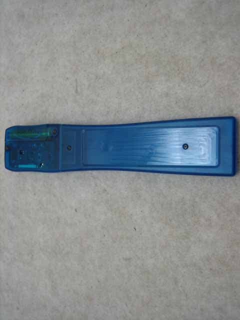
ODGCLIENTPAGER
Oct 12, 2006Client Pager
Equipment Class
CXX - Communications Rcvr for use w/ licensed Tx and CBs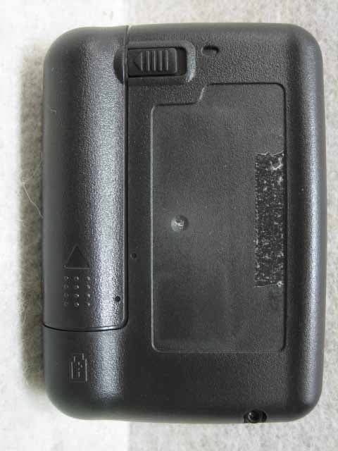
ODGT4POCSAGPLLUHF
Jul 12, 2006Alphanumeric 1Way Pager
Equipment Class
CXX - Communications Rcvr for use w/ licensed Tx and CBs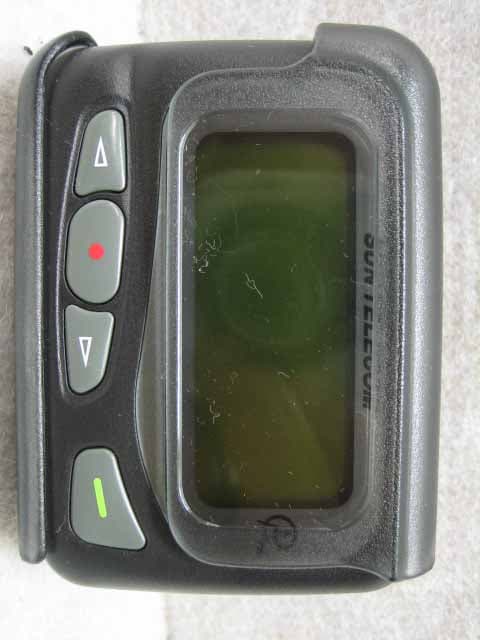
ODGT4POCSAGPLLVHF
Jul 12, 2006Alphanumeric 1WAY Pager
Equipment Class
CXX - Communications Rcvr for use w/ licensed Tx and CBs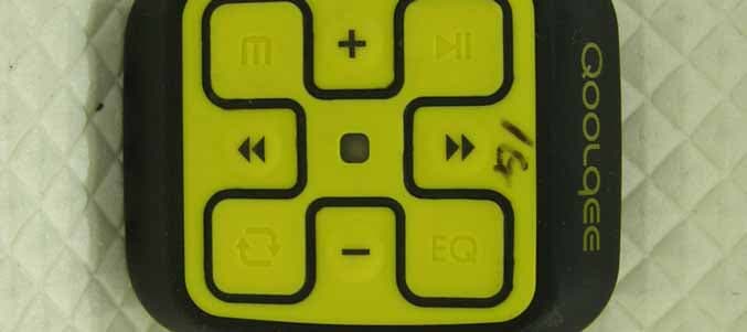
ODGQOOLQEEX
Jul 14, 2005Digital Audio Player
Equipment Class
JBP - Part 15 Class B Computing Device Peripheral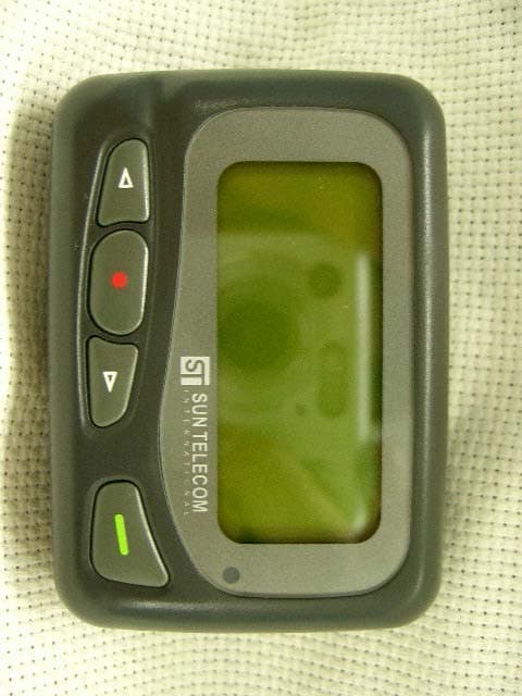
ODGT4
Feb 03, 2005Pager
Equipment Class
CXX - Communications Rcvr for use w/ licensed Tx and CBs